1
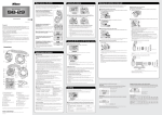
G52-BET
G52-BET
EGT & Boost Pressure
52mm Gauge
(with Optional Temperature Display)*
G52-BET
30
20
BOOST
PSI
10
7
6
EGT
X100
5
4
3
0
0
C
*Optional Temperature Display requires the purchase of GS-UT-80 /
GS-UT-120 / GS-OWT1-4 or GS-OWT1-8
WARNING & SAFETY INSTRUCTIONS
SAVE THESE INSTRUCTIONS - This manual contains IMPORTANT SAFETY INSTRUCTIONS for the G52-BET
Gauge.
DO NOT OPERATE THE GAUGE UNLESS YOU HAVE READ AND UNDERSTOOD THIS MANUAL AND THE GAUGE IS
INSTALLED AS PER THESE INSTALLATION INSTRUCTIONS. NOT SUITABLE FOR MARINE APPLICATIONS.
1. The G52-BET Boost & EGT Gauge is designed to provide an accurate indication of Boost Pressure and Exhaust
Gas Temperature (EGT) with an optional temperature indication. As accurate as the indication might be, these
gauges are not designed to be a substitute for regular maintenance and inspection by a qualified technician.
2. REDARC recommend that the G52-BET Boost & EGT Gauge be installed by a qualified technician.
3. Ensure the gauge face is cleaned only using soapy water and a soft cloth.
4. REDARC gauges are not suitable for installation into marine environments.
SPECIFICATIONS
G52-BET
6 - 16V (For 24V systems use GA-2412V)
30mA
Ø52mm x 42mm (not incl. studs, Bezel Ø56mm)
50g
2 Years
Boost/EGT Interface Box
Input Voltage Range
Nominal Current Draw
Gauge Dimensions
Gauge Weight
Warranty
Sensor
PRODUCT FUNCTION
20
BOOST
PSI
10
6
EGT
X100
5
4
3
0
0
C
Boost Pressure Gauge
120° Sweep
0 PSI - 35 PSI
EGT Gauge
120° Sweep
300°C - 700°C
20mm
4.5mm
42mm
Temp Gauge Digital
(optional)
-40°C - +160°C
Ensure that ‘P’-Clip
and star washers are
used during installation.
*(Either GS-UT-80, GS-UT-120, GS-OWT1-4 or GS-OWT1-8)
SAL.FOR.Instruction Manual.G52-BET - Version 2
1
36mm
7
52mm
30
44mm
55mm
The G52-BET is designed to measure boost pressure (between 0-35psi) and exhaust gas
temperature (between 300°C - 700°C) using the included Boost EGT Interface box.
The G52-BET also features an optional Temperature display for which a seperate sensor is
required*. The temperature is displayed on the digital readout at the bottom of the gauge and
is capable of measuring between -40°C & +160°C (depending on sensor chosen).
INSTALLATION
Find a suitable location for mounting the Gauge. REDARC offer a range of mounting
solutions - refer to www.redarc.com.au . It is important to ensure that your installation
meets any regulations regarding Field of View and Head Impact requirements.
Wire into vehicle as per the diagram below:
Programming
Switch
Multiple Gauge
Communication
Link
Black
Yellow
Purple
to Park Light
Positive
G52-BET
Rear View
Grey
to Dash Light
Negative*
ACC O
N
2:1 View
Orange
2A
fuse
2:1 View
Primary
Connector
Ground
Connection**
Secondary
Connector
Optional
Relay Output
EGT Probe***
Yellow
Green
Red
Orange
Yellow
Connect Hose
to Manifold****
Boost EGT
Interface
Black
Green
To Ignition
Black
CK
O
ART
ST
L
Brown
to Optional
Temp. Sensor
Note: DO NOT MOUNT IN ENGINE BAY
* Connect to a dash light that dims via the vehicle dimmer adjustment to ensure the gauge dims accordingly. If your
illumination circuit in your vehicle varies the positive voltage for dimming you will require a REDARC Enhanced Lighting
Controller (GA-ELC) to get the gauge to dim with your night-time driving lights.
** Ensure that the ground connection makes good contact with the vehicle ground. Poor grounding can cause incorrect
sensor readings. REDARC recommend removing any paint from the surface to ensure a bare metal on metal connection.
It is recommended that any wiring harnesses be covered using conduit or similar.
*** A steel 1/8 inch NPT bung (supplied) can be welded into a suitable location on the exhaust for mounting the EGT
sensor. Make sure the tip of the probe is in the centre of the exhaust pipe when mounted.
**** Connect the manifold pressure sensing hose to a suitable manifold hose using the ‘T’ piece provided. If no suitable
hose exists you may need to attach a suitable fitting into the manifold.
It is recommended that any wiring harnesses be covered using conduit or similar.
2
EGT PROBE INSTALLATION
The EGT Sensor should be installed in the following fashion by a suitably qualified installer:
1. Allow the engine to cool completely before commencing any work.
2. Locate the recommended sensor location point on the pipe. (Each make and model of vehicle will
have a specific location for the EGT sensors on the factory pipes. For aftermarket pipes, the system
may require a sensor location which is very different from the factory location - Consult your dealer or
manufacturer for the correct location for your system)
3. Have the pipe drilled and the included threaded boss welded into the appropriate position by a suitably
qualified installer.
4. Assemble and Install the compression cap and ferrule assembly onto the welded base and finger
tighten (Refer to diagram below for correct compression cap assembly)
5. Remove the black protective rubber cap from the end of the sensor probe and insert through the
installed mounting hardware. Tighten compression nut using an open-end wrench. Do not over tighten typically ½ turn past finger tight is sufficient.
6. If room permits, align the sensor transition and spring at a 90-degree angle to the exhaust pipe to
position the sensor tip correctly in the exhaust stream.
7. Connect the interface plug wires. (Refer to diagram below) Note: yellow wire should be connected to ‘+’,
red wire to ‘-’
d
Re ow
ll
Ye
REDARC also offer a range of different sized muffler clamp
mounts to suit the EGT Probe.
Refer to www.redarc.com.au for more details.
3
EGT PROBE SPECIFICATIONS
Thermocouple type
‘K’
Range
-148 to 2372°F (-100 to 1300°C)
Accuracy:
+/-0.4% of reading or about +/- 1.1°C (Special Limits of Error)
Probe diameter:
3/16 inch (0.187 inch) (4.75 mm)
Sensing Junction
Enclosed, Ungrounded
Response Time
1200 mS
Time Constant
Defined as the time required to reach 63.2% of an instantaneous
temperature change. Five time constants are required to approach 100 % of
the step change value
Outer Sheath Material
Inconel, melting point 2550°F (1400°C)
Cable
Stainless steel over braiding over Teflon™ insulated, stranded wires, 20
gauge
Compression Fitting
316 stainless steel, adjustable, 1/8 inch NPT male thread*
Wiring
+ = Yellow, - = Red
50mm
2000mm
53mm
23mm
76mm
1⁄8th NPT
76mm
O4.75mm
Sensor Location
* ¼ NPT Thread Compression fitting and steel bung available to Purchase at www.redarc.com.au
4
OPERATING INSTRUCTIONS
Selecting Gauge ID for multi-gauge systems
If your gauge is part of a multi gauge system (i.e. more than one gauge) and you wish to allow
programming from a single push button, connect the communication link wires together (see wiring
diagram on page 2). The Gauge “Id” of all linked gauges will need to be set to unique numbers.
Make sure that each gauge is set to a unique number or letter and that one gauge is set as the master
“Id.0”. The master gauge switch needs to be accessible for programming all the gauges. Each individual
gauge switch is only needed to set the programming ID.
Setup Instructions
Setup Mode is only required if you wish to change settings such as background color or other options. Setup
mode is indicated by the display of the programming symbol.
A detailed listing of the Setup Modes for the G52-BET can be found on page 6.
To enter Setup Mode:
2
CK
O
HOLD
3
4
RELEASE
To access
all settings
ACC
ON
ART
ST
L
1
OFF
To access
Gauge ID
Only*
Ignition Parklight
OFF
OFF
To view the next setting:
Push
(Momentary)
To change the setting & move to next mode:
Push to Cycle
Push & Hold
to Cycle
Release to
select
...
CK
O
ACC O
N
ART
ST
L
To save all changes:
OFF
Ignition Parklight
OFF
OFF
5
*Refer to “Selecting Gauge ID for multi-gauge systems”
at the top of this page
OPERATING INSTRUCTIONS
Setup Modes (Setup mode is indicated by display of the programming symbol
30
20
BOOST
PSI
10
7
6
EGT
X100
5
4
3
0
0
C
30
20
BOOST
PSI
10
7
6
EGT
X100
5
4
3
0
0
C
30
20
BOOST
PSI
10
7
6
EGT
X100
5
4
3
0
0
C
30
20
BOOST
PSI
10
7
6
EGT
X100
5
4
3
0
0
C
30
20
BOOST
PSI
10
7
6
EGT
X100
5
4
3
0
0
C
30
20
BOOST
PSI
10
7
6
EGT
X100
5
4
3
0
0
C
)
ID Select
Mode / Beeps:
1
Selections:
0 to 9 & A to F (16 selections)
For a single gauge setup do not change this selection as only the default selection
“Id.0” allows programming of modes.
Background Colour
Mode / Beeps:
2
Selections:
13 colours
Press and hold to select the programming button to select the colour that the gauge
backlight will display during normal operation. There are 13 different colour options.
Alert Colour
Mode / Beeps:
3
Selections:
2 Colours (Amber & Red)
Press and hold the programming button to select the colour that the gauge backlight
will change to when an alert is indicated (such as during an over temperature
warning).
Boost Warning Level
Mode / Beeps:
4
Selections:
10PSI - 30PSI
Press and hold the programming button until the desired warning pressure is set.
EGT Warning Level
Mode / Beeps:
5
Selections:
400°C - 700°C
Press and hold the programming button until the desired warning temperature is
set.
Optional Temp Meter Display Mode
Mode / Beeps:
6
Selections:
0.0°C or ‘nc’
If you have installed the optional temperature sensor and wish to display temperature
set this to 0.0°C, otherwise set to ‘nc’.
6
OPERATING INSTRUCTIONS
Setup Modes
30
20
BOOST
PSI
10
7
6
EGT
X100
5
4
3
0
0
C
30
20
BOOST
PSI
10
6
EGT
X100
5
4
3
0
C
30
20
BOOST
PSI
10
7
6
EGT
X100
5
4
3
0
0
C
30
20
BOOST
PSI
10
7
6
EGT
X100
5
4
3
0
DO NOT ADJUST THE OPTIONAL TEMP DISPLAY READING UNLESS THE SENSOR IS AT A STABLE
AND KNOWN TEMPERATURE.
Press and hold to slowly increase the temperature reading until it matches the
known temperature of the sensor.
7
0
Optional Temp Display Reading Adjust (Positive)
Mode / Beeps:
7
Selections: Increments by 1°C every 15 seconds
0
C
Optional Temp Display Reading Adjust (Negative)
Mode / Beeps:
8
Selections:
Decrements by 1°C every 15 seconds
Press and hold to slowly decrease the temperature reading until it matches the
known temperature of the sensor.
Optional Temp Display Coarse Warning Level Adjustment
Mode / Beeps:
9
Selections:
-40°C to +190°C
Press and hold to adjust the warning level for the Optional Temp Meter display,
release prior to desired level and use fine adjust. The Gauge will display ‘+’ or ‘-’
dependant on whether ‘above’ or ‘below’ is chosen in setting # 11.
Optional Temp Display Fine Warning Level Adjustment
Mode / Beeps:
10
Selections:
Decrements by 1 through 0-9 values
Press and hold to adjust the warning level for the Optional Temp Meter display, adjust
until desired warning level is reached. The Gauge will display ‘+’ or ‘-’ dependant on
whether ‘above’ or ‘below’ is chosen in mode # 11.
Relay Output
30
20
BOOST
PSI
10
THE OPTIONAL OUTPUT RELAY MUST BE CONNECTED TO ACCESS SETTINGS IN THIS STEP.
7
6
EGT
X100
5
4
3
0
0
C
Mode / Beeps:
11
Selections:
‘+’/‘-’ for above/below, pointers/levels
Press and hold the programming button to cycle through which warning will trigger
the relay output. A number indicates that the relay will be triggered by the optional
Temp Sensor. A pointer indicates the respective reading that will trigger the relay. After
each cycle, under(-) or over(+) temp mode is selected. For no relay output, select ‘nc’.
Note: Grey segment denotes a flashing portion of the Gauge screen during this mode of setup.
7
FREQUENTLY ASKED QUESTIONS
Centre black circle on gauge is flashing intermittently.
If the black centre ring is flashing and the gauge sounds an alarm, the gauge may have been
programmed to trigger a relay, but a relay is not detected. Check the relay connection or reprogram as
required. If no relay output is required refer to setup mode 11 and select ‘nc’.
What is the ‘peak hold’ (PH) feature?
When the gauge push button is pressed, the needle pointer(s) and/ or digital display will show the
highest/ peak reading for the function being monitored. This feature will reset when the vehicles ignition
is turned off.
Do I need to purchase the optional sensor for my gauge to work?
No, the standard features of the gauge will still work. To purchase the optional sensors please visit www.
redarc.com.au
What is the P-clip used for?
Attaching the p-clip to the back of the gauge ensures that the connectors are strongly fixed to the gauge,
thereby minimising the risk that they may come loose during installation and/ or rough driving conditions.
I cannot see my question here?
Please contact REDARC’s free technical support on (08) 8322 4848
Is the gauge compatible with existing vehicle sensors or other sensors available in the market?
No, the gauge is designed to work only with the sensors sold by REDARC.
What is the best mounting solution for my gauge?
REDARC offers a range of mounting panels and a mounting cup for its gauge range. Please ensure that
fitment of your gauge does not impede your driving field of view or create a head impact hazard.
Should I enclose the wiring harnesses in conduit?
REDARC recommends enclosing the supplied wiring harnesses in a suitable conduit that will protect the
wiring against sharp edges and/ or extreme temperatures.
Where should I install the black push button?
In most cases, once the gauge is set up and programmed the push button can be hidden behind the
vehicles instrument dash panel. However, if you believe that you may need to regularly change any of the
modes or wish to use the peak hold feature you should locate the push button in an accessible area (e.g.
at the back of the mounting cup).
Can I fit my gauge to a 24V vehicle circuit?
The gauge requires 12V to operate. A 24V to 12V adaptor is available for purchase (GA-2412V). This
can be purchased for all gauges, however the G52-VA and G52-VVA will only allow you to monitor the
charging performance of 12V batteries.
My gauge is too bright when driving (i.e. at night), what should I do?
You will need to purchase an Enhanced Lighting Controller (GA-ELC). This module is to be used when
you do not have a dimming circuit you can connect your gauges to, are using REDARC Gauges for all of
your instrumentation so require dimming or the dimming circuit in your vehicle does not dim the REDARC
gauges to your liking. The ELC allows you to program the night time brightness and colour of your gauges,
including dimming if connected to a dash dimmer (i.e. once programmed your gauge(s) will change colour
when turning on your park lights and back to a day light colour when you turn them off). You only require
one ELC for a complete set of gauges. It can be used in conjunction with the 24 volt adaptor (GA-2412V)
for a 24 volt system (ELC module is 24v capable).
8
TWO YEAR PRODUCT WARRANTY
Over the last three decades our company has established a reputation as the power conversion specialist.
A 100% Australian-owned company, we have met the needs of customers in transport and other industries through exciting, innovative thinking.
We believe in total customer satisfaction and practice this by offering our customers:
•
Technical advice free of jargon and free of charge
•
Prompt turnaround of orders throughout Australia and globally
•
Friendly, personalised, professional service and product support
In the unlikely event that a technical issue arises with a Redarc product, customers are encouraged to initially contact the Redarc Technical Support Team on (08) 8322 4848
or [email protected] for prompt and efficient diagnosis and product support.
Our goods come with guarantees that cannot be excluded under the Australian Consumer Law. You are entitled to a replacement or refund for a major failure and compensation for
any other reasonably foreseeable loss or damage. You are also entitled to have the goods repaired or replaced if the goods fail to be of acceptable quality and the failure does not
amount to a major failure.
The benefits of this Warranty are in addition to other rights and remedies available at law in respect of the Products and shall not derogate from any applicable mandatory statutory
provisions or rights under the Australian Consumer Law.
Redarc Electronics Pty Ltd atf the Redarc Trust trading as Redarc Electronics (“Redarc”) offers a warranty in respect of its Products where the Products are purchased from an
authorised distributor or reseller of Redarc by a person (“Purchaser”), on the terms and conditions, and for the duration, outlined below in this document (“Warranty”).
1. In this Warranty, the term Products means:
1.1 all products manufactured or supplied by Redarc (excluding its solar products
which are covered by Redarc’s Solar Product Warranty); and
1.2 any component of or accessory for any product in clause 1.1 manufactured or
supplied by Redarc.
Offer and duration of product warranties
2. Redarc warrants that its Products will be free, under normal application, installation,
use and service conditions, from defects in materials and workmanship affecting
normal use, for 2 years from the date of purchase (Warranty Period).
3. Where a Product malfunctions or becomes inoperative during the Warranty Period,
due to a defect in materials or workmanship, as determined by Redarc, then subject to
further rights conferred by the Australian Consumer Law on the Purchaser, Redarc will,
in exercise of its sole discretion, either:
3.1 repair the defective Product;
3.2 replace the defective Product; or
3.3 provide a refund to the Purchaser for the purchase price paid for the defective
Product,
without charge to the Purchaser.
4. The warranty given by Redarc in clause 3 covers the reasonable costs of delivery and
installation of any repaired or replaced Products or components of Products to the
Purchaser’s usual residential address notified to Redarc, together with the reasonable
costs of removal and return of any Products determined by Redarc to be defective.
5. If the Purchaser incurs expenses of the nature referred to in clause 4 in the context of
making a claim pursuant to this Warranty that is accepted by Redarc, the Purchaser will
be entitled to claim for reimbursement of those expenses which Redarc determines,
in exercise of its sole discretion, to be reasonably incurred, provided that the claim is
notified to Redarc in writing at the postal address or email address specified in clause
21 and includes:
5.1 details of the relevant expenses incurred by the Purchaser; and
5.2 proof of the relevant expenses having been incurred by the Purchaser.
Exclusions and limitations
6. This Warranty will not apply to, or include any defect, damage, fault, failure or
malfunction of a Product, which Redarc determines, in exercise of its sole discretion, to
be due to:
6.1 normal wear and tear or exposure to weather conditions over time;
6.2 accident, misuse, abuse, negligence, vandalism, alteration or modification;
6.3 non-observance of any of the instructions supplied by Redarc, including
instructions concerning installation, configuring, connecting, commissioning, use
or application of the Product, including without limitation choice of location;
6.4 failure to ensure proper maintenance of the Product strictly in accordance with
Redarc’s instructions or failure to ensure proper maintenance of any associated
equipment or machinery;
6.5 repairs to the Product that are not strictly in accordance with Redarc’s instructions;
6.6 installation, repairs or maintenance of the Product by, or under the supervision of,
a person who is not a qualified auto electrician or technician, or if non-genuine or
non-approved parts have been fitted;
6.7 faulty power supply, power failure, electrical spikes or surges, lightning, flood,
storm, hail, extreme heat, fire or other occurrence outside the control of Redarc;
6.8 use other than for any reasonable purpose for which the Product was
manufactured;
6.9 any indirect or incidental damage of whatever nature outside the control of Redarc.
7. Warranty claims in respect of a Product must be made in writing to Redarc at the postal
address or email address specified in clause 21 within the Warranty Period. Such
claims must include the following:
7.1 details of the alleged defect or fault and the circumstances surrounding the defect
or fault;
7.2 evidence of the claim, including photographs of the Product (where the subject of
the claim is capable of being photographed);
7.3 the serial number of the Product, specified on the label affixed to the Product; and
7.4 proof of purchase documentation for the Product from an authorised distributor or
reseller of Redarc, which clearly shows the date and place of purchase.
The return of any Products without the prior written instructions of Redarc will not be
accepted by Redarc.
8. Without limiting any other clause in this Warranty, Redarc has the right to reject any
Warranty claim made by a Purchaser pursuant to this Warranty where:
8.1 the Purchaser does not notify Redarc in writing of a Warranty claim within the
Warranty Period;
8.2 the Purchaser does not notify Redarc in writing of a Warranty claim within 1 month
of becoming aware of the relevant circumstances giving rise to the claim, so that
any further problems with the Product are minimised;
8.3 the serial number of the Product has been altered, removed or made illegible
without the written authority of Redarc;
8.4 the Purchaser is unable to provide proof of purchase documentation in accordance
with clause 7.4 or evidence that the Product was properly installed and removed (if
relevant), and that proper maintenance has been performed on the Product, by, or
under the supervision of, a qualified auto electrician or technician, in accordance
with the instructions of Redarc.
9. If the Product is found to be working satisfactorily on return to Redarc or upon
investigation by Redarc, the Purchaser must pay Redarc’s reasonable costs of testing
and investigating the Product in addition to shipping and transportation charges. Where
Redarc is in possession of the Product, the Product will be returned to the Purchaser on
receipt of the amount charged.
10. Any replaced Products or components of Products shall become the property of Redarc.
11. Redarc may, in exercise of its sole discretion, deliver another type of Product or
component of a Product (different in size, colour, shape, weight, brand and/or other
specifications) in fulfilling its obligations under this Warranty, in the event that Redarc
has discontinued manufacturing or supplying the relevant Product or component at the
time of the Warranty claim, or where such Product or component is superior to that
originally purchased by the Purchaser.
Other conditions of Warranty
12. If the Purchaser acquired a Product for the purpose of resupply, then this Warranty shall
not apply to that Product.
13. In particular, the sale of a Product via an online auction, online store or other internet
website by a party that is not an authorised distributor or reseller of the Product will be
deemed to be a resupply within the meaning of the Australian Consumer Law and will
render this Warranty void, as Redarc has no control over the storage, handling, quality
or safety of Products sold by such persons.
14. A Purchaser shall only be entitled to the benefit of this Warranty after all amounts owing
in respect of the Product have been paid.
15. While Redarc warrants that the Products will be free from defects in materials and
workmanship in the circumstances set out in this Warranty, to the maximum extent
permitted by law Redarc does not warrant that the operation of the Products will be
uninterrupted or error-free.
16. To the maximum extent permitted by law, Redarc’s determination of the existence of
any defect and the cause of any defect will be conclusive.
17. Spare parts or materials for the Products are guaranteed to be available for a period of
at least 2 years after purchase of the Products.
18. The agents, officers and employees of any distributor or reseller of the Products and of
Redarc are not authorised to vary or extend the terms of this Warranty.
19. Redarc shall not be responsible or liable to the Customer or any third party in
connection with any non-performance or delay in performance of any terms and
conditions of this Warranty, due to acts of God, war, riots, strikes, warlike conditions,
plague or other epidemic, fire, flood, blizzard, hurricane, changes of public policies,
terrorism and other events which are beyond the control of Redarc. In such
circumstances, Redarc may suspend performance of this Warranty without liability for
the period of the delay reasonably attributable to such causes.
20. If a clause or part of a clause in this Warranty can be read in a way that makes it illegal,
unenforceable or invalid, but can also be read in a way that makes it legal, enforceable
and valid, it must be read in the latter way. If any clause or part of a clause in this
Warranty is illegal, unenforceable or invalid, that clause or part is to be treated as
removed from this Warranty, but the rest of this Warranty is not affected.
Redarc’s contact details
21. Redarc’s contact details for the sending of Warranty claims under this Warranty are:
Redarc Electronics Pty Ltd
23 Brodie Road (North), Lonsdale SA 5160
Email: [email protected]
Telephone: +61 8 8322 4848
Copyright © 2014 Redarc Electronics Pty Ltd. All rights reserved.
WARG52-BET - REV2
Whilst all care was taken to ensure the contents of this manual were accurate at the time of
printing, we take no responsibility for any errors or omissions.