1
Kar av an Tr ailer s, Inc .
A Leader in Trailer Transportation
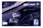
OWNER’S MANUAL
Enclosed is operator’s instructions and warranty information for your new Karavan Trailer.
Please read them carefully before operating.
Watercraft
Trailer
Boat Trailer
Snowmobile Trailer
Utility Trailer
Congratulations on your purchase of a new Karavan Trailer. We are confident that you will be completely satisfied for years to come with the quality and versatility of your Karavan Trailer. We have paid special attention to
all the details that make your investment choice a step above the others, to ensure this satisfaction. We do however
suggest that you read this manual completely and follow all recommendations made, to ensure that the excellence
of your Karavan Trailer will last for many years.
We at Karavan Trailers, Inc. take pride in our products and our ability to continue to provide you, the customer, with a quality recreational trailer, which meets and exceeds your expectations.
Product and Specifications subject to change without notice.
Lit - 00114 - NA-A-4 Owners Manual
1/1/10
.DU DY DQ 7U DLOHU V ,QF 4XDOLW\3ROLF \
.DUDYDQ7UDLOHUV,QFLVGHGLFDWHGWRFXVWRPHUVDWLVIDFWLRQFRQWLQXRXVLPSURYHPHQWDQG
FRVW:HKDYHFRPPXQLFDWHGWKLVWKURXJKRXWRXURUJDQL]DWLRQWKURXJKRXUWKUHH´&·Vµ
&XVWRPHU6DWLVIDFWLRQ²:HUHFRJQL]HWKDWZHDUHKHUHEHFDXVHRIRXUFXVWRPHUVDQGZH
ZLOOVWULYHWRPHHWWKHLUH[SHFWDWLRQV
&RQWLQXRXV,PSURYHPHQW²$ZD\RIOLIHDW.DUDYDQ:HZLOOXVHWKLVYHKLFOHWRGULYH
RXUTXDOLW\V\VWHPDQGPDNHXVDZRUOGFODVVGHVLJQPDQXIDFWXUHUDQGLQQRYDWRU
&RVW².DUDYDQZLOOFKDOOHQJHWKHVXSSO\FKDLQDQGEHFRPSHWLWLYHLQWKHLUPDUNHWDQG
GHOLYHUWKHEHVWFRVWHIIHFWLYHSURGXFWWRWKHLUFXVWRPHU
&RQWDFW8VKHOS#NDUDYDQWUDLOHUVFRP
&XVWRPHU6HUYLFH3DUWV:DUUDQW\
Karavan Trailers, Inc. - Warranty Policy
Karavan Trailers, Inc. warrants each new Karavan Trailers Trailer to be free from defects in materials and
workmanship for a period of one (1) years from date of purchase or two (2) years from the date of manufacturer. Karavan
Trailers shall repair or replace, without charge, any parts found to be defective because of imperfect workmanship or
materials, within a reasonable time after the trailer is returned at purchaser's expense to any Karavan Trailers authorized
distributor or dealer.
Karavan Trailers will have a limited lifetime warranty against manufacturer defects on the frame.
Who is covered?
This warranty is extended to the original purchaser only and does not extend to any other persons to whom the trailer may
be transferred. Warranty on tires shall be made through the nearest representative for the tires.
What is not covered?
Karavan Trailers limited warranties do not cover the costs of damage caused by normal wear and tear or caused by
environmental factors. (Including, but not limited to chemicals, salt, or contact with hazardous materials)
Purchased parts such as winches, lights, couplers, brakes, tongue jacks, actuators, and springs are exempt from Karavan
Trailers limited warranty.
Galvanizing and/or other finishes are exempt from warranty.
Any items that were found modified or altered in any way; nor shall the warranty apply to any
defect or malfunction which was caused by damage, unreasonable use, or failure to provide reasonable and necessary
maintenance.
The warranty will not cover damage caused by overloading the trailer beyond stated capacities or the use of improperly
installed weight distribution hitches in conjunction with hydraulic surge brakes.
Due to the highly corrosive conditions a trailer is exposed to, rust formation/ corrosion is not covered.
Other Limitations
Races, bearings and seals are covered for 180 days from date of purchase. Any implied warranties, obligations, or
liabilities, including but not limited to, any implied warranty of merchantability, shall be limited in duration to the twoyear duration of the written limited warranty. Some states do not allow limitation on how long an implied warranty lasts,
so the above limitation may not apply to you. The use of any unit as part of a rental fleet, or use for commercial purposes
voids this warranty.
The following are exclusions of Karavan Trailers Warranty:
• Loss of time
• Inconvenience
• Towing charges
• Travel expenses
• Lodging
• Telephone
• Gas
• Loss or damage to personal property or loss of wages
Karavan Trailers, Inc. shall not be liable for any incidental or consequential damages for breach of this or any other
warranty expressed or implied.
Reporting Safety Defects
(Reporting Safety Defects page, under brakes)
Karavan Trailers Inc.
100 Karavan Drive
Fox Lake, WI 53933
If you believe that your vehicle has a defect that could cause a crash or could cause injury or death, you
should immediately inform the National Highway Traffic Safety Administration (NHTSA) in addition to
notifying Karavan Trailers Inc.
If NHTSA receives similar complaints, it may open an investigation, and if it finds that a safety defect
exists in a group of vehicles, it may order a recall and remedy campaign. However, NHTSA cannot
become involved in individual problems between you, your dealer, or Karavan Trailers Inc.
To contact NHTSA, you may either call the Vehicle Safety Hotline toll-free at
1-888-327-4236 (TTY: 1-888-424-9153), go to http://www.safecar.gov; or write to:
Administrator, NHTSA, 1200 New Jersey Avenue S.E. , Washington, DC 20590
You can also obtain other information about motor vehicle safety from http://safecar.gov.
Warranty Information
Caliber Products
952-469-3400
Fulton/Wesbar
Auto Flex-Knott Inc.
920-928-6875
, Cables
815-877-5700
Tredit Tire & Wheel
Ultra-Trac
800-537-2925
;IEX/EVEZER8VEMPIVW -RG [ERXXSXLERO]SYJSVKMZMRKYWXLIEFMPMX]XSWIVZI]SY;IETTVIGMEXI]SYVFYWMRIWWERH[ERXXSQEOIWYVI
XLEX]SYVLMKLIWXI\TIGXEXMSRWEVIQIX 4PIEWIXEOIEJI[QMRYXIWXSJMPPSYXXLMWWYVZI]XSLIPTYWWXVMZIJSVXSXEPGYWXSQIVWXEXMJEGXMSR
:MWMXYWEX[[[OEVEZERXVEMPIVWGSQXSJMPPMXSYXSRPMRI'SRXEGX4LSRI
,S[WEXMWJMIHEVI]SY[MXL]SYV/EVEZER8VEMPIV#
:IV]7EXMWJMIH
7EXMWJMIH
3ZIVEPP5YEPMX]
:EPYI
4YVGLEWI )\TIVMIRGI
*MVWX 9WI)\TIVMIRGI
9WEKI)\TIVMIRGI
%JXIV4YVGLEWI7IVZMGI
[EVVERX] VITEMV LIPTHIWO
2IYXVEP
,S[SJXIRHS]SYYWIXLI8VEMPIV#
3RGIE[IIOSVQSVI
XSXMQIWEQSRXL
3RGIEQSRXL
)ZIV]QSRXLW
XMQIWE]IEV
3RGIE]IEVSVPIWWSJXIR
3ZIVEPP LS[WEXMWJMIHEVI]SY[MXLXLI8VEMPIV#
:IV]7EXMWJMIH
7SQI[LEX7EXMWJMIH
2IYXVEP
9RWEXMWJMIH
:IV]9RWEXMWJMIH
'SQTEVIHXSSXLIV8VEMPIVWXLEXEVIEZEMPEFPI
[SYPH]SYWE]XLEXXLI/EVEZER 8VEMPIVMW©
1YGLFIXXIV
7SQI[LEXFIXXIV
%FSYXXLIWEQI
7SQI[LEX[SVWI
1YGL[SVWI
(SR´XRSSVRIZIVYWIH
9RWEXMWJMIH
:IV]9RWEXMWJMIH
2SX%TTPMGEFPI
;LEXHIEPIVWLMTHMH]SYTYVGLEWI]SYV/EVEZER8VEMPIVJVSQ#
CCCCCCCCCCCCCCCCCCCCCCCCCCCCCCCCCCC
,S[WEXMWJMIHEVI]SY[MXL]SYVXSXEPI\TIVMIRGI
[MXLXLIHIEPIVWLMT#
:IV]7EXMWJMIH
7SQI[LEX7EXMWJMIH
2IYXVEP
9RWEXMWJMIH
:IV]9RWEXMWJMIH
-J]SYLEZIGSRXEGXIH/EVEZER 8VEMPIVW -RG GYWXSQIVWIVZMGI
[IVIEPPTVSFPIQWVIWSPZIHXS]SYVGSQTPIXIWEXMWJEGXMSR#
=IW F]XLIGSQTER]SVMXWVITVIWIRXEXMZIW
=IW F]QISVWSQISRISYXWMHIXLIGSQTER]
2S XLITVSFPIQ[EWRSXVIWSPZIH
2STVSFPIQW
2SGSRXEGX[MXLGYWXSQIVWIVZMGI
;LEX[SYPH]SYPMOIXSXIPP/EVEZER8VEMPIVW -RG EFSYX]SYV
I\TIVMIRGI[MXLSYVTVSHYGX#
;MPP]SYYWITYVGLEWIE/EVEZER8VEMPIVEKEMR#
(IJMRMXIP][MPP
4VSFEFP][MPP
1MKLXSVQMKLXRSX
4VSFEFP][MPPRSX
(IJMRMXIP][MPPRSX
,S[PMOIP]EVI]SYXSVIGSQQIRHE/EVEZER8VEMPIVXSSXLIVW#
(IJMRMXIP][MPPVIGSQQIRH
4VSFEFP][MPPVIGSQQIRH
1MKLXSVQMKLXRSX
4VSFEFP][MPPRSXVIGSQQIRH
(IJMRMXIP][MPPRSX
&EWIHSR]SYVI\TIVMIRGI[MXLE/EVEZER8VEMPIV
LS[PMOIP]EVI]SYXSEKEMRFY]E/EVEZER8VEMPIV#
:IV]0MOIP]
7SQI[LEX0MOIP]
2IYXVEP
9RPMOIP]
:IV]9RPMOIP]
4LSRI
)QEMP
8LERO]SYJSV]SYVJIIHFEGO;IWMRGIVIP]ETTVIGMEXI]SYV
LSRIWXSTMRMSRERH[MPPXEOI]SYVMRTYXMRXSGSRWMHIVEXMSR[LMPI
TVSZMHMRKTVSHYGXWERHWIVZMGIWMRXLIJYXYVI
-J]SYLEZIER]GSQQIRXWSVGSRGIVRWEFSYXXLMWWYVZI]TPIEWI
GSRXEGX
/EVEZER8VEMPIVW -RG
/EVEZER(VMZI
*S\0EOI ;-
Affix
First Class
Stamp Here
KARAVAN TRAILERS, INC.
100 Karavan Drive
Fox Lake, WI 53933
Please cut out, fold in half and tape on all three sides to send back
/ Ball Coupling
Disc Brakes Service Information (Trailer Buddy)
DL
Fulton
Trailer Winch Operators Manual (DL)
Trailer Winch Operators Manual (Fulton)
Autoflex Warranty Info
7-37
38-44
45
46-47
48-49
50-51
52
53
54-61 6
62-63
64-65
66-67
68-69
70
70
70
71-74
75-76
77-78
77-78
81-84
11
BALL COUPLING
WARNING: The installed ball coupler MUST be properly secured to the hitch ball of the towing vehicle. After assembly
and attachment, pull up and down on the ball coupler to make sure the hitch ball is fitting snugly on the hitch ball. There must
be no play between the hitch ball and ball coupler. If there is play, tighten the adjustment nut until no play is present.
If the adjustment nut is too tight, the handle will not lock.
If the ball coupler is not secured properly, it could come lose while the trailer is in motion, possibly causing property damage,
SERIOUS PERSONAL INJURY or DEATH.
CHECK BALL COUPLER TIGHTNESS OFTEN
All disc brake trailers require your tow vehicle to have a 5 pin connector
(show below)
WARNING: The warnings, cautions, and instructions discussed in this instruction manual cannot cover all possible
conditions and situations that may occur. It must be understood by the operator that common sense and caution are factors which
cannot be built into this product, but must be supplied by the operator
2
LITERATURE NUMBER MPD
85778
HYDRAULIC
SURGE BRAKE SYSTEM
• Installation • Operation • Maintenance
Effective 3/7/01
SAFETY ALERT SYMBOLS
Safety Symbols alerting you to potential personal safety
hazards. Obey all safety messages following these symbols.
WARNING
CAUTION
avoid possible
injury or death
avoid possible injury
and/or property damage
FOR YOUR SAFETY READ ALL INSTRUCTIONS
BEFORE OPERATING BRAKE SYSTEM
Installer: Provide this instruction to consumer.
Consumer: Keep documents for future reference.
The installation instructions must be followed to insure safe
operation of Atwood brake actuators and foundation brakes.
Failure to install according to installation instructions nullifies
warranty.
DRUM BREAK APPLICATIONS:
• For best performance use Atwood Foundation Brakes with an
Atwood Brake Actuator. These components are system
matched.
DISK BRAKE APPLICATIONS:
• Use only Atwood 80360, 80366, 88730, 88730 Disc Brake
Actuators for disc brake applications.
• Atwood Disc Brake Actuators have been tested for compatibility with Kodiak brand and Reliable brand Disc Brake
Systems.
• To be used with a maximum of 4 2-1/4” diameter calipers.
• For more information call Atwood Mobile Products (815-8775700), Kodiak Trailer Components
(817-284-2324), or Reliable Tool & Machine
(219-347-4000).
WARNING
PERSONAL INJURY & PRODUCT DAMAGE
• Observe maximum trailer weight for Atwood brake actuator Gross
Vehicle Weight Rating (GVWR) and tongue load.
• Do not exceed these capacities. Gross Vehicle Weight Rating is total
weight of trailer fully loaded included personal belongings. Know
your trailer GVWR.
CAUTION
PRODUCT DAMAGE / BRAKE FAILURE
• Use only a 2” machined or forged ball with Atwood brake actuator.
Ball capacity must be equal to or greater than trailer GVWR. DO NOT
use a worn hitch ball-it is unsafe and must be replaced.
• DO NOT submerge actuator in water. Water may enter and corrode
master cylinder, contaminating Brake System, causing brake failure.
INSTALLATION
WARNING
BRAKE FAILURE
• Brake actuator MUST BE installed with frame stops in contact with
trailer tongue.
STRAIGHT TONGUE - BOLT ON APPLICATION (FIG 1)
8000 LB. BRAKE ACTUATORS SAE CLASS 4 - DISC AND DRUM APPLICATIONS
8000 LB. GVWR, MAX. TONGUE LOAD 1000 LB. - DO NOT EXCEED THESE RATINGS
PART NO. 83005, 83010 - DRUM APPLICATION / PART NO. 80366 - DISC APPLICATION
1. Determine proper location of brake actuator on trailer tongue. Set
actuator on trailer tongue, push down and back until frame stops (FIG
1-A), making contact with tongue.
2. Drill 17/32” holes in trailer tongue where bolt holes are positioned.
3. Reinforcement of trailer tongue spacer must be 1/2” ID pipe or equiv.
(FIG 3-A).
4. Attach brake actuator to trailer tongue with 1/2” diameter bolts (3)
S.A.E. grade 8 lockwasher (3) and nuts (3) (FIG 1-B). Torque nuts to
110-120 ft/lbs.
6000 LB. BRAKE ACTUATORS SAE CLASS 4 - DISC AND DRUM APPLICATIONS
6000 LB. GVWR, MAX. TONGUE LOAD 900 LB. - DO NOT EXCEED THESE RATINGS
PART NO. 82542, 82543, 83153, 83154, 84131, 84132, 84133, 88730, 88740
1. Determine proper location of brake actuator on trailer tongue. Set
actuator on trailer tongue, push down and back until the frame stops
(FIG 1-A), making contact with tongue.
2. Drill 17/32” holes in the trailer tongue where bolt holes
are positioned.
3. Reinforcement of trailer tongue spacer must be 1/2” ID pipe or equiv.
(FIG 3-A).
4. Attach brake actuator to trailer tongue with 1/2” diameter bolts (2)
S.A.E. grade 5 or greater lockwasher (2) and nuts (2) (FIG 1-B).
Torque nuts to 70-80 ft. lbs.
WARNING
BRAKE FAILURE
• Trailer tongue must have adequate strength to support attachment of
brake actuator without mounting nuts losing torque during life of trailer.
• Trailer tongue must be properly reinforced to prevent any potential
loosening of brake actuator during service.
STRAIGHT TONGUE - WELD ON APPLICATION (FIG 2)
WELDING INSTRUCTIONS
• M.I.G. OR STICK - 5/32” Fillet weld minimum.
• M.I.G. WELDING - Use A.W.S. ER 70S-3 or 6 wire or equivalent with
a diameter of .035 - .045. The recommended shielding gas mixture is
75% - 95% Argon & 25% - 5% CO2.
• STICK WELDING - Use E6011 A.W.S. welding rod or equivalent.
Recommended machine settings for specific electrode diameter are as
follows: 1/8” electrode set power between 115-130 Amps DC or 5/32”
electrode set power between 140-160 Amps DC.
8000 LB. BRAKE ACTUATORS SAE CLASS 4
8000 LB. GVWR, MAX. TONGUE LOAD 1000 LB.
- DO NOT EXCEED THESE RATINGS
PART NO. 83000 - DRUM APPLICATION / PART NO. 80360 - DISC APPLICATION
1. Determine proper location of brake actuator on trailer tongue. Set
actuator on trailer tongue, push down and back until frame stops (FIG
2-A), making contact with tongue.
2. Using WELDING INSTRUCTIONS weld actuator to trailer with a minimum of 9” weld per side. Make a 5/32” fillet weld (FIG 2-B).
3. Make sure to return weld on front end of frame of trailer up inside
actuator frame to forward frame stop (see FIG 2-C).
6000 LB. BRAKE ACTUATORS SAE CLASS 4 - DISC AND DRUM APPLICATIONS
6000 LB. GVWR, MAX. TONGUE LOAD 900 LB.
- DO NOT EXCEED THESE RATINGS
PART NO. 82542, 82543, 83153, 83154 - DRUM APPLICATION ONLY
PART NO.88740 - DISC APPLICATION ONLY
1. Determine proper location of brake actuator on trailer tongue. Set
actuator on trailer tongue, push down and back until frame stops (FIG
2-A), making contact with tongue.
2. Using WELDING INSTRUCTIONS weld actuator to trailer with a minimum of 7” weld per side. Make a 5/32” fillet weld (FIG 2-B).
3. Make sure to return weld on front end of frame of trailer up inside
actuator frame to forward frame stop (see FIG 2-C).
3
33
CAUTION
DAMAGE TO CABLE
• Breakaway cable and hook must not touch ground during welding
operation.
• DO NOT use actuator if latching mechanism does not operate freely.
Contact Atwood Service Department as 815-877-5700
A-FRAME - WELD-BETWEEN APPLICATION (FIG 4)
FOUNDATION BRAKES (FIG 5-8)
1. Check if axle has brake flanges (FIG 5-A) if so, skip step No. 2.
2. If axle does not have brake flanges, install flanges as follows:
a. Secure flange to back of brake assembly (FIG 5-B) with 4 bolts (FIG 5-C).
b. Insert brake assembly into hub and drum assembly (FIG 5-D). Drum
must completely cover surface of brake shoes (FIG 6). Be certain
brake assembly back plate does not contact drum edge (FIG 6-A),
and inside edges of shoes are not in contact with hub or drum.
c. Adjust brake shoes snugly against drum by inserting brake adjusting tool (FIG 7-A & B) through adjusting slot (FIG 7-C). Back plate must
be centered within drum diameter after adjustment. Visually check
for equal space between edge of back plate and edge of drum.
d. Mount brake/drum/flange assembly on spindle and secure with
spindle nut. Be sure brake/drum/flange assembly is fully mounted
on spindle.
e. With trailer level, locate top of brake flange parallel with bottom of
trailer frame (FIG 8)
f. Tack wild flange to axle (a tack weld is a small semipermanent
weld used for securing).
g. Remove brake/drum assembly.
h. Finish welding flange securely to axle, using WELDING
8000 LB. BRAKE ACTUATORS SAE CLASS 4 - DISC AND DRUM APPLICATIONS
8000 LB. GVWR, MAX. TONGUE LOAD 1000 LB.
- DO NOT EXCEED THESE RATINGS
PART NO. 83000 - DRUM APPLICATION / PART NO. 80360 - DISC APPLICATION
1. Position actuator between A-Frame members with leading edge of AFrame located 8” from back of actuator (FIG 4).
2. Using WELDING INSTRUCTIONS weld actuator to trailer tongue by
welding along entire length where trailer frame contacts actuator.
Weld must be a minimum of 9” along each side (FIG 4).
6000 LB. BRAKE ACTUATORS SAE CLASS 4 - DISC AND DRUM APPLICATIONS
6000 LB. GVWR, MAX. TONGUE LOAD 900 LB.
- DO NOT EXCEED THESE RATINGS
PART NO. 82542, 82543, 83153, 83154 - DRUM APPLICATION ONLY
PART NO.88740 - DISC APPLICATION ONLY
1. Position actuator between A-Frame members with leading edge of AFrame located 5” from back of actuator (FIG 4).
2. Using WELDING INSTRUCTIONS weld actuator to trailer by welding
along entire length where trailer frame contacts actuator. Weld must
be a minimum of 7” along each side (FIG 4).
CAUTION
PRODUCT DAMAGE
• Breakaway cable and hook must not touch ground during welding
operation.
• Weld trailer A-Frame members together with additional bracing (i.e.
cross members or jack mounting plates (FIG 4). Brake actuator alone is
not designed to withstand torsional twist of trailer.
• Cross member(s) should be comparable in strength to trailer frame, and
located as close to brake actuator as possible.
NOTE: If Atwood top and bottom jack mounting plates are used (MPD
82570 or MPD 80255) (FIG 4A), move jack mounting plates as close to
brake actuator as possible and weld along entire area where plates and
trailer frame contact.
Use WELDING INSTRUCTIONS.
PAINTING THE BRAKE ACTUATOR
DIP PAINTING PROCEDURE
NOTE: Carefully perform procedure in order given.
1. Plug vent hole in master cylinder boot.
2. Fully apply brake actuator.
3. Plug master cylinder outlet port (1/8)" NPTF thread).
4. Plug master cylinder reservoir port to prevent paint from entering
master cylinder.
5. Paint brake actuator.
6. Remove all plugs and fully release brake actuator.
7. Inspect for paint contamination of master cylinder and shock absorber
shaft after painting. Replace parts if contaminated with paint.
8. Continue with MANDATORY FUNCTIONAL CHECK AFTER PAINTING.
SPRAY PAINTING PROCEDURES
1. Fully apply brake actuator.
2. Plug master cylinder outlet port (1/8" NPTF thread).
3. Plug master cylinder reservoir port preventing paint from entering master cylinder.
4. Paint brake actuator.
5. Fully release brake actuator & paint unpainted portions of socket assembly.
6. Remove all plugs.
7. Inspect for paint contamination of master cylinder and shock absorber
shaft after painting. Replace parts if contaminated with paint.
44 4
CAUTION
TRAILER COULD DISCONNECT
MANDATOR FUNCTIONAL CHECK AFTER PAINTING
1. Check function of ball socket and latching mechanism by inserting,
locking and removing a 2" diameter hitch ball. Once hitch ball is fully
inserted in socket, release handle must close completely and freely
when released.
2. If ball socket and latching mechanism does not close completely and
freely as described above:
a. Check for paint build-up in ball socket and clean if necessary.
b. Lubricate ball socket and latching mechanism with SAE 30 oil and
work mechanism by inserting, locking and removing a 2" diameter
hitch ball until latching mechanism does work freely.
3. Move back-up lever to indicated back-up position and lock. Operate
brake actuator back-up lever, return to towing position freely using
only return spring force. Clean off excess paint and lubricate as necessary to ensure lever assembly operates freely.
INSTRUCTIONS.
3. Mount brake and shoe assembly to flange. Wheel cylinder must be at
top of brake with rubber boot toward the front of trailer. For 7" brakes
use nuts and lockwashers provided (torque to 50 ft. lbs.)
4. Mount drum and bearings on axle spindle, secure with washer and
spindle nut.
5. Tighten spindle nut securely and then loosen or untighten nut one
quarter (1/4) turn 90°.
6. Consult installation instructions to connect brake piping MPD 85869.
NOTE: Consult Atwood Engineering Dept. when using non-Atwood
brake piping or other components or when questions arise concerning
installation or application.
7. Raise one trailer wheel at a time, remove dust clip from adjusting slot
at lower part of back side of brake assembly and insert brake adjusting
tool (FIG 7). Adjust brake shoes out by moving end of adjusting tool as
illustrated, only until adjustment wheel (FIG 7-D) will not turn. When
this condition is felt by rotating wheel, back-off (loosen) adjustment
until wheel will just turn freely.
INSTALLATION - DISC BRAKE ACTUATOR SOLENOID BACK-UP VALVE
WARNING
DEATH OF PERSONAL INJURY
• This system requires the solenoid wire leads be connected ONLY into
the tow vehicle back-up light circuit.
8,000 LB. ACTUATORS are equipped with a solenoid back-up valve.
1. Connect the solenoid valve wire leads to the tow vehicle back-up light
circuit.
2. Connect trailer brake line to actuator.
3. Bleed brake system.
6,000 LB. ACTUATORS are not equipped with a solenoid back-up valve.
When a solenoid back-up valve is desired please contact Atwood for the
solenoid back-up kit. Atwood Mobile Products 815-877-5700.
To install Atwood solenoid back-up valve1. Remove the plug in return port of master cylinder (this is the upper port
in the master cylinder).
2. Install straight barbed fitting (torque to 16-20 in/lb).
3. Install assembly in supply port of master cylinder (this is the lower port
in the master cylinder).
4. Connect the solenoid wire leads only into the reverse back-up light circuit.
5. Connect trailer brake line to actuator.
6. Bleed brake system.
FOR DISC BRAKE SYSTEMS
CAUTION
DAMAGE TO BRAKE ACTUATOR OR VEHICLE
• If brass orifice fitting is not installed (FIG 10B), trailer-braking action
may cause vehicle(s) to shake during brake applications.
The brass orifice fitting installed in master cylinder (FIG 10A) of brake
actuator assembly must remain in hydraulic circuit to brakes (FIG 10C)
of trailer.
If brass orifice fitting must be moved to accommodate plumbing (FIG
10E) for a back up solenoid valve (FIG 10D), it must be replaced in
hydraulic circuit in line to brakes.
WARNING
DEATH OR PERSONAL INJURY
brakes to drag and heat up, causing failure.
9. Cross safety chains under tongue & securely attach to bumper or frame
of tow vehicle.
CAUTION
• Contaminated brake fluid in system could plug brass orifice fitting.
This could render brakes inoperative.
Be especially careful to clean all fittings, tubing and threads between
master cylinder and brass orifice fitting. A very small particle of dirt or
thread sealant can plug hole in orifice.
• Do not use Teflon® tape on fittings
• If a liquid or paste thread sealant is used, keep it back two threads
from end of male fitting.
•Do not apply sealant to female threads. Clean female threads thoroughly.
BLEED BRAKE SYSTEMS
CAUTION
BRAKE FAILURE
• DO NOT use brake fluid drained from brake system in refilling master
cylinder. Brake fluid can be contaminated from the system.
1. Remove master cylinder filler cap and fill reservoir with DOT type 3
or 4 automotive brake fluid.
2. Check all hydraulic line fittings & connections to make sure they are
leak free.
3. At brake assembly, connect a bleeder hose to bleeder fitting on wheel
cylinder and submerge free end in a container with brake fluid. DO NOT
reuse brake fluid.
NOTE: Use power bleeder or bar with 2" diameter hitch ball attached (FIG 9).
Do not use breakaway cable for purpose of bleeding brake system. If a
power bleeder is used air pressure 35 PSI is most effective.
NOTE: Bleed brake on rear most axle furthest from the actuator first.
4. Loosen bleeder fitting at top of brake assembly.
5. Apply actuator (See FIG 9) and tighten bleeder fitting. Return actuator
to forward position. Again, loosen bleeder valve one turn and apply
actuator. Repeat this procedure until fluid expelled from bleeder hose
is free of air bubbles. It is helpful to lower the trailer tongue to promote air bubble movement in the brake tubing. It is also helpful to tap
gently along the brake tubing during brake bleeding to keep air bubbles from sticking to the inside of the brake tubing. During this procedure, master cylinder reservoir fluid level must be maintained at no
less than 1/2 full and no more than 1/2 " from top of reservoir.
6. When no air bubbles are visible, close bleeder valve securely and
remove bleeder hose.
7. Repeat STEP 1-6 for remaining brake, then brakes on forward axle.
8. If installation is tandem axle with brakes on both axle, repeat bleeding
procedure on rear axle brakes for the second time to assure positive
purging of all air in system.
9. After bleeding has been completed, re-check fluid level in master
cylinder.
OPERATION - TOWING
CAUTION
TRAILER MAY DISCONNECT
• Release handle (FIG 12A) must be fully closed before towing.
• Do not force release handle into closed position.
1. Position actuator ball socket above 2" ball.
NOTE: Do not damage actuator when backing up towing vehicle for hookup.
2. Hold release handle in open position (FIG 11A). Release handle must
be held in fully open position to remove from or place on ball.
3. Lower trailer tongue until ball rests in ball socket.
4. Close release handle (FIG 12A). Release handle will close freely with
finger pressure when ball is properly inserted into ball socket.
5. To make sure actuator is securely latched onto ball, extend trailer
tongue jack to ground and lift car and trailer combination 2" to 4". If
ball does not disengage, actuator is securely attached.
6. Insert padlock or bolt through lock hole for theft protection.
7. Connect breakaway cable solidly to bumper or frame of tow vehicle as
near to center as possible. Cable must hang clear of trailer tongue and
long enough to permit short radius turns without pulling breakaway
cable forward.
8. Make sure breakaway cable (FIG 13C) is in released position with indicator bead (FIG 13B) touching or resting against cable spring stop (FIG 13A).
CAUTION
PRODUCT DAMAGE
• DO NOT use breakaway cable as a parking brake.
NOTE: Check location of breakaway cable periodically during each trip,
indicator should rest against spring stop. Accidental application will cause
TRAILER DAMAGE
• Safety chains must be used.
10. Retract jack fully. Remove and store caster, if applicable
11. Check for proper car-trailer hook-up: tow vehicle and trailer should
be level with positive tongue load. For further information, consult a
dealer or Atwood Service Department.
12. Back-up lever knob must be positioned in TOWING POSITION (FIG 15-A).
13. If actuator is used with equalizing hitch, be sure hanger chains (FIG 14D)
hang between straight down and forward up to 34° (FIG 14C). DO NOT
use less that 6-1/2" hanger chain length (FIG 14x). For optimum brake
performance, hang chains forward 34° (FIG 14).
14. DO NOT use Atwood brake actuator with a sway controller, unless prior
Atwood Engineering approval of sway control system has been received.
15. You are now ready to tow your vehicle.
CAUTION
PRODUCT & TRAILER DAMAGE
• Avoid sharp turns. This could bend, create extreme stress or fracture
either actuator of trailer tongue.
BACKING UP
1. Follow step 1 through 15 for TOWING.
2. If equipped with solenoid valves skip to STEP 5.
3. Before backing up a slope or through soft ground, pull trailer forward
slightly to assure actuator socket is in fully forward position.
4. Move lever knob on side of actuator downward from TOWING POSITION
(FIG 15A) along curved slot in actuator frame to BACK-UP POSITION (FIG
15B). Slot has a notch at bottom of its travel. Push lever knob down to
engage locking notch.
5. Back trailer up.
CAUTION
PRODUCT & TRAILER DAMAGE
• Avoid sharp turns. This could bend, create extreme stress or fracture
either actuator or trailer tongue.
6. If trailer is to be uncoupled from tow vehicle after backing with lever
knob engaged, block all trailer wheels and pull forward slightly to take
strain off actuator. Uncouple actuator by lifting release handle and
raising trailer tongue. Make sure lever knob is in TOWING POSITION (FIG
15A) when uncoupling from trailer.
CAUTION
PRODUCT & TRAILER DAMAGE
• Before towing trailer, lever knob must be disengaged and in TOWING
POSITION.
MAINTENANCE
1. Keep all links and pivots lubricated to prevent rusting and ensure ease
of operation. Use SAE 30 oil, lubricate inside release handle and
inside actuator body reached from underside of actuator.
NOTE: Lubricate hitch ball with conventional automotive grease or a
lubricant made for hitch balls.
2. Check for leaks in brake system. Periodic checks should be made on
all hoses and fittings to guard against cuts and worn hoses which may
cause failure (leaks, rupturing under pressure, and collapsing).
Replace defective hoses.
3. Check brake fluid level in master cylinder reservoir. Keep filled to
within 1/2" from top of reservoir. Use only DOT Type 3 or 4 brake
fluid. Check electrical connections on reverse solenoid if system has
one. Electrical connections should be sound and free of corrosion.
Check reverse solenoid function.
CAUTION
BRAKE FAILURE
• DO NOT fill master cylinder reservoir with used brake fluid.
• DO NOT fill reservoir beyond 1/2" from top.
• DO NOT overfill, brake fluid will damage paint.
• DO NOT use silicone type brake fluid.
• Yearly inspect brakes for excessive wear, replace lining if necessary.
5
55
4. Flush system yearly or when system is known to be contaminated. For
Disc Bake Systems remove orifice fitting (FIG 10) before flushing.
Check fitting orifice to make sure it is clear. The orifice is .015" DIA
it may be replaced if it is plugged with Atwood P/N # MPD 80777.
The orifice fitting must be replaced after flushing the system.
NOTE: Wheel bearing and seals should be inspected and packed at this time.
ADJUSTING 7" & 10" DRUM BRAKES
Trailer brakes should be adjusted after the first 1,000 miles of use and at
least every 2,000 miles of use thereafter, in addition, trailer brakes
should also be inspected for excessive wear, replace lining if necessary
and adjusted at the beginning of each season or yearly. Wheel bearings
and seals should be inspected and packed at this time.
SQUEAKING, CLATTER OR CHUCKING
CONDITION
SOLUTION
LACK OF HITCH BALL LUBRICATION - - - - - - - - - Lubricate with conventional auto-
motive grease or commercial
lubricant made for hitch balls
BINDING LINKAGE & PIVOTS ON
BRAKE ACTUATOR - - - - - - - - - - - - - - - - - - - - - - - - Oil linkage & pivots on brake
LOOSE HITCH BALL - - - - - - - - - - - - - - - - - - - - - - LOOSE HITCH - - - - - - - - - - - - - - - - - - - - - - - - - - - ACTUATOR LOOSE ON TRAILER FRAME - - - - - - HITCH BALL WORN OR TOO SMALL - - - - - - - - - OVERHEATED BRAKES - - - - - - - - - - - - - - - - - - - - BROKEN BRAKE DRUM(S) - - - - - - - - - - - - - - - - - LOW BRAKE FLUID LEVEL - - - - - - - - - - - - - - - - - -
Raise one trailer wheel at a time, chock
opposite wheel to prevent trailer from
rolling. Remove dust clip from adjusting
slot at lower part of back side of brake
assembly and insert brake adjusting
tool. Adjust brake shoes out until
wheels will not turn by moving end of
adjusting tool towards top of brake.
When this condition is felt, by rotating
wheel, back-off (loosening) adjustment
until wheel will just turn freely.
Atwood Hardware Systems & Components Limited Warranty
Atwood Mobile Products warrants to the original consumer purchaser this
product will be free of defects on material and workmanship for a period
of two years from the date of purchase. Atwood’s liability hereunder is
limited to the replacement of product, repair of product or replacement of
product with a reconditioned product, at the discretion of the manufacturer. The warranty is void if the product has been damaged by accident,
unreasonable use, neglect, tampering or other causes not arising from
defects in material workmanship. The warranty extends to the original
consumer purchaser of the product only, and is subject to the following
conditions:
1. For two (2) years commencing with the date of purchase, Atwood will
replace or repair any Hardware System & Components that are found
to be defective by Atwood in material or workmanship.
2. In the event of a warranty claim, the Original Purchaser must contact
the Atwood Consumer Service Department,
4750 Hiawatha Drive, Rockford, Illinois 61103-1298, Telephone: 815877-5700 Fax: 815-877-7469. Warranty claim service must be performed as approved by the Atwood Consumer Service Department.
Warranty replacement hardware systems and components or parts will
be furnished freight prepaid. Labor cost to repair or replace will be limited to the amount of the original purchase price of the systems and
components. The replaced warranty products or parts become the property of Atwood Mobile Products and must be returned to the Atwood
Consumer Service Department freight prepaid, unless prior arrangements have been made.
3. This limited warranty is valid only when the product is applied,
installed, maintained and operated in accordance with this Atwood
Installation, Maintenance and Operating Manual (MPD 87984). Any
deviation from these recommended specifications must be approved in
writing by Atwood.
4. Any implied warranties are limited to the duration of this limited warranty as stated above. Atwood does not assume responsibility for consequential damages or loss, including loss of use of vehicle, loss of
time, inconvenience, expense of gasoline, telephone, travel, lodging,
loss or damage to personal properties, or loss of revenues. Some states
do not allow limitations on how long an implied warranty lasts or limitations on consequential damages, so the above limitations may not
apply to you. This limited warranty gives you specific legal rights
which may vary from state to state.
6/00
TROUBLE SHOOTING GUIDE
Guides are only intended for use on Atwood® products by service technicians who have successfully completed Atwood® training. This guide
should be used in conjunction with appropriate Instruction Manual provided with the product and any applicable Industry Standards. This is not
intended to be a complete list. Please direct questions concerning service
of Atwood® products to 815-877-5700 before proceeding.
WARNING
PERSONAL INJURY AND/OR PRODUCT DAMAGE
6
6 6
• If any of the following conditions develop, trailer must not be used
until proper corrective action is taken.
WORN OUT SHOCK ABSORBER - - - - - - - - - - - - - PARTIAL APPLICATION OF BREAKAWAY CABLE BRAKES IMPROPERLY ADJUSTED - - - - - - - - - - - BROKEN BRAKE RETURN SPRING - - - - - - - - - - - SEIZED ACTUATOR MASTER CYLINDER - - - - - - WORN OUT BRAKE SHOES - - - - - - - - - - - - - - - - - LEAKY WHEEL CYLINDER - - - - - - - - - - - - - - - - - -
actuator
Inspect hitch & tighten
Inspect hitch & tighten
Inspect brake actuator & tighten
Replace
Replace wheel bearing
Replace brake drum(s) & check
brake shoes
Fill & bleed brakes, per IOM
instructions
Replace
Fully release breakaway cable
Check brakes for adjustments per
IOM instructions
Replace return spring
Replace/rebuild actuator master
cylinder
Replace brake shoes and check
brake drums
Replace/rebuild wheel cylinders
and replace brake shoes. Clean
drums and other hardware
RELEASE HANDLE DOES NOT CLOSE EASILY
CONDITION
SOLUTION
OVERSIZED BALL - - - - - - - - - - - - - - - - - - - - - - - - - Check ball size
BALL NOT FULLY INSERTED INTO SOCKET - - - - - Check for proper ball size. Check
to see if tongue jack is fully
retracted. Hold release handle
open when inserting ball.
FOREIGN MATERIAL IN ACTUATOR SOCKET - - - - Clean and lubricate
BRAKE OVERHEATING, SIDE PULL, BRAKES DO NOT OPERATE,
POOR BRAKE PERFORMANCE
CONDITION
SOLUTION
ONLY ONE BRAKES IS APPLYING - - - - - - - - - - - - - Check brake adjustment per IOM
instructions.
LEAKING WHEEL CYLINDER - - - - - - - - - - - - - - - - Check and replace wheel cylinder
SEIZED WHEEL CYLINDER PISTON - - - - - - - - - - -
FOREIGN MATERIAL IN BRAKE UNIT - - - - - - - - - LOW HYDRAULIC FLUID LEVEL - - - - - - - - - - - - A BENT SHOULDER BOLT - - - - - - - - - - - - - - - - - - A BEND PUSH ROD IN THE SHOCK ABSORBER - A DAMAGED SOCKET ASSEMBLY - - - - - - - - - - - BROKEN/PINCHED BRAKE LINES - - - - - - - - - - - - BRAKE ACTUATOR FRAME DAMAGED - - - - - - - - WORN BRAKE SHOE(S) - - - - - - - - - - - - - - - - - - - - -
and bleed brakes per IOM
instructions.
Check and rebuild/replace wheel
cylinder and bleed system per
IOM instructions.
Clean thoroughly
Fill and bleed brakes, per IOM
instructions.
Replace
Replace shock absorber
Replace actuator
Replace
Replace actuator
Replace broken shoe(s)
TOWING VEHICLE SHAKING BACK AND FORTH
CONDITION
SOLUTION
WORN VEHICLE SUSPENSION - - - - - - - - - - - - - - - Replace shock absorber
HITCH NOT SECURE - - - - - - - - - - - - - - - - - - - - - - - Tighten all bolts and nuts
UNDER-SIZED HITCH BALL - - - - - - - - - - - - - - - - - Ball should be 2"
machined/forged type
EXTENDED STORAGE INSTRUCTIONS
Preventative maintenance is recommended for extended periods of storage.
1. Check brake system for proper fluid level in master cylinder, bleed all lines.
2. Lubricate all links and pivots to prevent any rusting.
3. Remove wheel and drum assemblies and spray a good anti-corrosion compound (CRC formula 5-56) under rubber boot on forward end of brake
wheel cylinder. Avoid spraying drum and brake lining.
4. Grease all bearings and reinstall wheel and drum assemblies.
5. Make sure breakaway cable is fully released.
6. After extended storage refer to MAINTENANCE Steps 1 through 5, to insure
trailer readiness for towing.
7. Adjust drum brakes.
PROPER TOWING CHECKLIST
Inspect brake fittings for leaks.
Adjust brakes every 2000 miles.
Lubricate all mechanical moving parts.
Inspect the breakaway cable for any kinks.
Verify a one-piece 2" ball is used, without chips, dirt or hairline cracks.
Securely attach safety chains to trailer and tow vehicle.
For proper braking, trailer should set level when attached to tow vehicle
to produce a positive tongue load.
DOT 3 or 4 brake fluid should be used in master cylinder and fill it from
1/2 full to 1/2" from top of cylinder reservoir
8
8
10
10
12
15
17
18
19
21
22
23
26
31
33
34
35
37
7
WARNINGS
THROUGHOUT THIS MANUAL, THE FOLLOWING SIGNAL WORDS AND SYMBOLS ARE
USED TO ALERT YOU TO POTENTIAL HAZARDS. OBEY ALL MESSAGES AND
INSTRUCTIONS. FAILURE TO FOLLOW THESE MESSAGES AND INSTRUCTIONS MAY
LEAD TO POSSIBLE INJURY OR DEATH.
! DANGER
왕
DANGER indicates an imminently hazardous
situation which, if not avoided, will result in
death or serious injury.
! WARNING
왕
WARNING indicates a potentially hazardous
situation which, if not avoided, will result in
death or serious injury.
! CAUTION
왕
CAUTION indicates a potentially hazardous
situation which, if not avoided, may result in
minor or moderate injury.
CAUTION
CAUTION used without the alert symbol
indicates a potentially hazardous situation
which, if not avoided, may result in property
damage.
INTRODUCTION
Your trailer is equipped with the Model A-60, A-75 or A-84 Hydraulic Brake Actuator.
Trailer brakes will automatically apply whenever the tow vehicle’s brakes are applied.
They will develop stopping (deceleration) force in direct proportion to the stopping force
generated by the tow vehicle.
! WARNING
왕
This actuator should only be installed on trailers with
a Gross Vehicle Weight Rating (GVWR) of 6000 lbs. or
less (A-60), or GVWR of 7500 lbs. or less (A-75), or
GVWR of 8400 lbs. or less (A-84).
! WARNING
왕
The A-60 & A-75 actuators are designed for use with
a 2” hitch Ball. The hitch ball and tow vehicle must
be rated to handle the actual Gross Vehicle Weight
(GVW) of the trailer and load. A-84 actuator is
designed for use with a 2 5/16” ball.
ACTUATOR
The Model A-60 actuator maximum load rating is 6000 pounds, the maximum load rating
for A-75 is 7500 pounds and the maximum load rating for A-84 is 8400 pounds. Models
can support a maximum static tongue load of 750 pounds (A-60 & A-75), or 840 pounds
(A-84). The maximum load rating is for the total weight of the trailer and boat fully loaded
including all gear and includes tongue weight.
Read and familiarize yourself with this handbook. Also, review and understand the
guidelines and requirements for towing published by the tow vehicle manufacturer and
the trailer manufacturer.
Keep this handbook in your tow vehicle or with your trailer for future reference. Contact
your dealer or our customer service department if additional information is desired.
You the user are responsible for the consequences of inadequate maintenance,
deliberate misuse, alteration or damage to the actuator.
1
8
Trailer braking is controlled by the actuator mounted on the tongue of the trailer. When
the tow vehicle brakes are applied, the “surge” or “push” of the trailer toward the tow
vehicle automatically applies and synchronizes the trailer brakes with the tow vehicle
brakes. The coupler slides into the actuator applying force to a piston inside of a master
cylinder, which applies the trailer brakes.
HOW THE ACTUATOR WORKS
At constant speed, the brake actuator master cylinder piston is in the free (extended)
position; and the trailer brakes are not applied. The shock absorber controls random
application of the trailer brakes when towing on rough roads. See Figure 1.
FIGURE 1: ACTUATOR EXTENDED (RUNNING POSITION)
When the tow vehicle slows down, the trailer moves toward the tow vehicle. The actuator
slides over the coupler, applying force to the master cylinder piston in direct proportion
to how fast the tow vehicle is slowing and how much the trailer weighs. The piston
moves into the master cylinder, building pressure to apply the trailer brakes. The shock
absorber makes sure the brakes are applied and released smoothly. See Figure 2.
FIGURE 2: ACTUATOR COMPRESSED (STOPPING)
NOTE:
You may notice a slight clunk when accelerating from a dead stop or anytime
after braking, which is normal due to the nature of surge brakes. Contact your
dealer or UFP if the clunk becomes excessive, or if you have any concerns
about the performance of your brake system.
TRAILER BREAKAWAY SYSTEM
All actuators must have a way to apply the trailer
brakes should the trailer become completely
detached from the towing vehicle. The breakaway
!
cable is the third line of defense after trailer
separation. Before the breakaway cable is pulled, the
coupler must become detached from the hitch ball and then the safety chains must fail.
At this time the breakaway cable is pulled which will apply a braking force to the trailer.
Note: The breakaway system is not intended to lock up the trailer brakes after tow
vehicle separation but rather to apply just enough braking force to keep the trailer from
free-wheeling down the road. The breakaway system must be reset manually after it has
been activated.
왕 WARNING
DO NOT USE THE BREAKAWAY SYSTEM AS A PARKING BRAKE.
2
9
HOW TO INSTALL THE ACTUATOR
The actuator is to be used only with brakes specifically designed for trailer service. It
should not be used with any custom built, one-of-a-kind brakes because such
combinations have not been tested and evaluated. The actuator is designed for use with
one or two sets of either 10” or 7” drum breaks. It can also be used with one set of 8 1/2”
or 12” drum brakes. The basic actuator may be used with one set of UFP 10” disc or 12”
disc brakes. A special version is available for operating 2 sets of 8 1/2” drum brakes and
2 sets of UFP 10” disc brakes. Contact factory for further information.
Some trailers do not have adequate brakes for the
trailer, how it is used, or where it is towed. Not
!
having adequate trailer brakes will increase stopping
distance and cause more lining wear or overheating
on your vehicle and trailer. You may wish to discuss this subject with your trailer dealer.
왕 WARNING
TOWING REQUIREMENTS - EQUIPMENT
! WARNING
왕
You must match the tow vehicle and trailer. Also
make sure the hitch, hitch ball, and safety chain
ratings match or are greater than the trailer Gross
Vehicle Weight Rating.
TOW VEHICLE
Review the tow vehicle owner’s manual and trailering guide for information on towing
capacity, requirements for brakes, use of weight-distributing hitches and other towing
recommendations. Make sure your vehicle combination complies with the Gross
Combined Weight Rating (GCWR) limits specified by the tow vehicle manufacturer.
BRAKE LAWS
Brake laws vary from state to state. Be sure you understand and comply with
regulations. Make sure your vehicle combination has adequate brakes and keep them
properly adjusted and in good working condition. Brake laws usually set minimum
standards. You may wish to consider a better braking capability depending on the tow
vehicle, miles driven and towing terrain.
HITCH
The tow vehicle’s hitch must have a rating equal to or greater than the trailer GVWR.
HITCH BALL
The hitch ball must have a rating equal to or greater than the trailer GVWR. Use only a
quality machined, or forged ball, with a smooth finish. The A-60 & A-75 actuator coupler
will only accept 2” diameter balls. Make certain a 2” diameter ball of the correct load
rating is used. Balls must be within the limits of 1.970” - 2.000” diameter when measured
in all directions. Balls larger than 2.000” or out of round will not fit the coupler socket.
Balls smaller than 1.970” can cause shock loading and a sudden disconnection could
result at worse case. The A-84 requires a 2 5/16” hitch ball with a rating equal to or
greater than the trailer GVWR. The 2 5/16” ball must be within the limits of 2.282” - 2.312”
diameter when measured in all directions. Hitch balls may be purchased from your
dealer or UFP.
3
10
HITCH HEIGHT
For proper tow vehicle and trailer hookup and towing performance, the tow vehicle and
trailer are to be level with respect to the ground after hitching up. If your trailer is not
level, equipment is available to raise or lower the hitch ball. A weight equalizing hitch or
load support suspension equipment may also be required to keep the tow vehicle level
and to properly load each axle.
왕
SAFETY CHAINS
Adequate safety chains must be used and conform to the Society of Automotive Engineers
(SAE) J684 standard, “TRAILER COUPLING AND HITCHES - AUTOMOTIVE TYPE”.
! WARNING
왕
The strength rating of EACH length of safety chain
must be equal to the trailer GVWR.
Make sure that your safety chains are fastened to the frame of the trailer and to the hitch
or tow vehicle frame. Safety chains fastened directly to the hitch ball or to the bumper,
are not acceptable and will not pass vehicle inspections. Connect safety chains using a
crossed pattern under the tongue.
FIGURE 3 TYPICAL DOUBLE SAFETY CHAIN INSTALLATION
SWAY CONTROL DEVICES
! WARNING
왕
Trailer sway control devices that restrict operation of
the actuator MUST NOT be used. These devices can
limit the how much the trailer brakes work.
The coupler must be able to slide freely into and out of the actuator when your vehicle slows
down.
4
11
WEIGHT DISTRIBUTING HITCHES
Weight distributing (equalizing) hitches may be used. Chain must be vertical (straight up
and down) under pulling load (actuator extended). Excessive tongue weight beyond
actuator rating must be avoided as it will reduce brake performance and could damage
the actuator. Always follow hitch and weight distributing manufacturer’s instructions.
FIGURE 4 TYPICAL WEIGHT DISTRIBUTING HITCH INSTALLATION
HOW TO ATTACH THE TRAILER
To connect the trailer to the tow vehicle, open the coupler mechanism (see instructions
below) and if necessary, raise the trailer jack. Slowly back up the tow vehicle so that the
hitch ball is under the coupler.
! WARNING
왕
Do not move the trailer to the tow vehicle. When the
trailer is moved without a tow vehicle, the brakes do
not work.
If the latch accidentally opens, the coupler could detach from the hitch ball. The hitch pin
should fit easily into the hole (Figure 5). If it does not, the coupler latch is not completely
closed. Every time the coupler is attached to the hitch ball, make sure the coupler
completely covers the hitch ball and the lift handle will not open without pushing the
push button to the side (A-60) & (A-84) or pulling up on the trigger (A-75). If the hitch pin
is damaged or lost, contact UFP for a free replacement pin.
! WARNING
왕
You must install either the hitch pin (supplied) or a
padlock (1/4” or 5/16” shank) into the hitch pin hole
before towing to prevent the coupler latch opening
accidentally. See figure 5.
5
12
TO OPEN THE COUPLER (A-60) & (A-84)
A-60
Remove hitch pin from hole in the side of the
coupler. Push button on top of handle to the side.
While holding button to the side, raise handle by
lifting front with two fingers. The coupler should
unlatch easily. If not, the ball may be oversized or
eggshaped, foreign matter could be lodged in
coupler ball socket, or the coupler is pushing on the
hitch ball. Check to make sure the wheel on the
tongue jack is raised or that you are not parked
downhill. Correct these conditions, then try to open
the handle. Examples include tongue jack forcing
front of trailer up or trailer pushing against tow
vehicle. Correct as necessary.
TO CLOSE COUPLER (A-60) & (A-84)
A-75
Place coupler over the ball, lower coupler and close
handle. You will hear a “click”. Handle should close
with finger pressure. If handle will not close freely,
ball is not fully inserted into socket, is oversized or
eggshaped. DO NOT FORCE HANDLE. If necessary,
replace ball with a quality unit that meets SAE
specifications. Insert hitch pin into hole on side of
coupler.
TO OPEN THE COUPLER (A-75)
Remove hitch pin from hole on side of coupler latch
handle. While lifting up on latch handle trigger, lift
up on latch handle until it rotates about 90 degrees
and stops. The coupler should unlatch easily. If not,
the ball may be oversized or egg-shaped, foreign
matter could be lodged in coupler ball socket, or the
coupler is pushing on the hitch ball. Check to make
sure the wheel on the tongue jack is raised or that
you are not parked downhill. Correct these
conditions, then try to open the handle. Examples
include tongue jack forcing front of trailer up or
trailer pushing against tow vehicle. Correct as
necessary.
A-84
FIRST: PUSH BUTTON TO SIDE
SECOND: LIFT LATCH HANDLE
HITCH PIN HOLE
TO CLOSE COUPLER (A-75)
Place coupler over the ball, lower coupler and close
HITCH PIN
handle. Coupler handle should close with minimal
force. If handle dose not close, ball is not fully
FIGURE 5
inserted into socket, is oversized or eggshaped. DO
OPENING COUPLER
NOT FORCE HANDLE. If necessary, replace ball with
a quality unit that meets SAE specifications.
Visually verify that ball is completely inserted into coupler socket by looking into hole on
top of coupler body. Insert hitch pin into hole on side of coupler latch handle.
! WARNING
왕
You must install either the hitch pin (supplied) or (A-60
& A-75 only) a padlock (1/4” or 5/16” shank) into the
hitch pin hole before towing to prevent the coupler
latch opening accidentally. See figure 5.
6
13
DO NOT tow your trailer if latch handle will not remain
closed or with the handle open. Check to see if
!
coupler is locked by lifting up on the handle without
pushing the button to the side before towing. If the
handle opens, the hitch ball is not the right size, oversized, or eggshaped, or the latch
parts have been damaged. If the latch is damaged, contact UFP for replacement parts.
왕 WARNING
BREAKAWAY CABLE
Secure the breakaway cable to the bumper or frame of tow vehicle as close to center as
possible (do not attach to safety chains). The cable MUST hang clear of the trailer tongue
and be long enough to permit sharp turns without pulling the cable and will not be applied
unless the safety chains fail. Do not loop S-hook over breakaway cable to attach it.
! WARNING
왕
Never tow a trailer without the breakaway cable
secured to the tow vehicle.
If the breakaway is accidentally pulled and the brakes applied, find out why this
happened and fix the problem. Inadvertent setting of the brakes by pulling the breakaway
cable is the single most common mistake users make. To prevent light pulls from
accidentally setting trailer brakes, a small metal clip has been installed on breakaway
cable in front of the indicator bead (A-60 & A-75 only). The clip will not inhibit the action
of the breakaway mechanism during actual breakaway conditions. However, if breakaway
should occur the clip will be destroyed and should be replaced. Spare clips are attached
to the cover of this manual.
To retract the breakaway cable, slide the coupler fully forward and push up on the
pushrod release bracket located on the underside and behind the hitch ball socket to
allow the bead to retract into the actuator. This will release the trailer brakes. Install new
clip on breakaway cable in front of bead.
FIGURE 6 CHECKING AND RESETTING BREAKAWAY CABLE
If pushing up on the bracket dose not release the brakes or if it is hard to push, insert a
pry bar into the 5/16” hole behind the bracket. Use pry bar to stroke push rod backwards
to relieve load on bracket. Push up on bracket and hold up while releasing pry bar. The
pushrod release bracket should now move freely and brakes should be released.
(figure 7)
Check to see if the actuator is reset. Extend the actuator fully. Remove the cap from the
top of the actuator and pull the plug from top of the reservoir cover. While looking at
fluid in the reservoir, manually compress actuator. In the first 1/8” of coupler movement
the fluid in the reservoir should “splash” or “ripple” slightly. If it does, the actuator is
working properly.
7
14
FIGURE 7 STROKING THE PUSHROD TO RELEASE BRAKES
Note: If brakes can not be released using above method or if pushrod release bracket will
not move, it is damaged beyond serviceability. Contact UFP for repair parts.
SAFETY CHECKS BEFORE TOWING
! WARNING
왕
FAILURE TO READ AND FOLLOW THESE
INSTRUCTIONS MAY RESULT IN SERIOUS
INJURY OR DEATH.
ACTUATOR CONDITION
Check the actuator and coupler for damage, bent parts, and excessive wear. Replace
parts if needed. Contact UFP for replacement parts. Check that the bolts that attach the
actuator (if equipped) to the trailer are tight.
! WARNING
왕
COUPLER
Check that the coupler (latch) handle closes (down)
completely when the hitch ball is in the coupler. To
make sure the coupler is secured to the hitch ball,
look under the coupler and check. Also, while the coupler is attached, raise the front of
the trailer 2” to 4” with the tongue jack. If the coupler stays connected, it is secure. If
coupler dose not stay attached try the attachment and attachment check again. If coupler
will not stay attached to hitch ball, or latch opens inadvertently, DO NOT TOW TRAILER –
CONTACT UFP.
REMEMBER TO LOWER TRAILER/RAISE JACK BEFORE TOWING.
Note: At times the coupler can push on the hitch ball when parked. Check to make sure
the tongue jack is raised or that you are not parked downhill. Correct these conditions,
then try to open the handle.
! WARNING
왕
TONGUE WEIGHT
It is very important your trailer have 5% to 10%
tongue weight when it is loaded and the tongue is
level. For example, a trailer weighing 4,000 pounds
MUST have a tongue weight of at least 200 pounds. This will help reduce trailer from
swaying from side to side (“fishtailing”). A bathroom scale can be used to find the
tongue weight of the trailer.
8
15
Not having enough tongue weight can cause the trailer to sway from side to side and the
coupler to rattle up and down as you go down the road. This is very important and if the
tongue weight is not in the 5% to 10% range, you should move the cargo (gas tank,
anchor, fishing tackle, cooler) from the back to the front or back to front to make sure
the tongue weight is in the range. On some trailers, the axle or axles can be moved to
change the tongue weight.
! WARNING
왕
BREAKAWAY CABLE
Check the breakaway cable each time before you tow
and at gas and rest stops to make sure it has not
been damaged. Check the location of the indicator
bead and clip. The clip should be in place (A-60 & A-75 only) and the bead should not be
outside the actuator. Accidental application will cause brakes to drag and heat up.
! WARNING
왕
! WARNING
왕
! WARNING
왕
! WARNING
왕
SAFETY CHAINS
Make sure that your safety chains are secured to the
tow vehicle per the instructions supplied by trailer
manufacturer. SAE recommendations are listed in
“Requirements-Equipment” section.
FLUID LEVEL
Check the fluid in the master cylinder reservoir each
time before you tow or if you see break fluid leakage.
Refill as required.
HITCH BALL
Make sure a hitch ball of proper size and correct
load rating is used. A film of clean grease on the ball
will extend coupler and ball life and stop squeaking.
Wipe ball clean and renew film periodically.
TOW VEHICLE HITCH
The hitch on the tow vehicle must be of the proper
load rating and in good condition. If hitch is of the
receiver type, make sure receiver pull pin is in place
and safety pin is installed.
! WARNING
왕
TRAILER JACK
! WARNING
왕
AUTOMATIC BRAKE LOCKOUT (if equipped)
The electrical lead from the solenoid valve must be
connected to the tow vehicle backup lights. A “click”
should be heard when the tow vehicle is shifted into
reverse and the backup lights come on.
Trailer jack must be fully retracted and caster wheel
removed (if necessary) before towing.
To check: Have someone listen for the sound while driver is in the tow vehicle. Keep the
emergency brake on and one foot on the brake pedal to avoid accidentally backing up.
! WARNING
왕
ELECTRICAL WIRING
Plug in connector and check signal, brake and
running lights.
9
16
BACKING
When you back your car and trailer, the coupler will move back and apply the trailer
brakes. The brakes will apply at different levels depending on how fast you back up, the
type of brakes, the road or surface you are on, and the angle of your trailer. If your trailer
has drum brakes, most of the time the trailer brakes won’t be a problem when backing
up. Below are options that help you back up with the trailer brakes.
Some trailers with disc brakes need an electrical solenoid control to allow the trailer to
back up. This control is wired th the back up lights on the tow vehicle and when the tow
vehicle is put into reverse, this control dose not allow the trailer brakes to apply.
BRAKE LOCKOUT BRACKET
A simple lockout is included on some models to stop the coupler from moving back
when you back the trailer. The brake lockout bracket is used when you need to back over
soft ground or up a hill. Use it as follows:
1.
Put or place the brake lockout into slot behind roller pin on the side of the actuator.
2.
Slide the brake lockout completely forward in slot. Washer will keep brake lockout
from falling out while backing up.
When you pull the trailer forward and the actuator extends, the brake lockout should fall
out of the slot. This makes sure the actuator will function when stopping.
! WARNING
왕
THE BRAKE LOCKOUT BRACKET MUST
BE REMOVED BEFORE TOWING OR THE
TRAILER BRAKES WILL NOT WORK.
FIGURE 8
BRAKE LOCKOUT CAP
This type of lockout is an available option. It allows trailers to be backed up over soft
ground or up inclines without fully engaging the brakes. This lockout is designed to
disengage when the trailer is pulled forward after backing up. Therefore it must be
manually reset prior to each back up.
Operating Brake Lockout Cap
1.
To operate lockout cap, the actuator must be fully extended. This can be done by
pulling the trailer forward slowly.
2.
With the lockout cap in the TOW (forward) position, depress the button in the front
of the cap and rotate the cap clockwise toward the BACKING position until it stops.
The button should remain down.
3.
Back the trailer.
10
17
4.
If the trailer needs to be pulled forward, there are two options:
a) Pull the trailer forward and let the coupler move forward. The control cap will
rotate (reset) and you will have to turn it back to the BACKING position in order to
back up.
b) If you have backed up an incline, allow the tow vehicle to move forward slowly so
the coupler stays back. This keeps the control in the engaged (BACKING)
position so you can back up again.
After the trailer is removed from the tow vehicle after
backing up, block the trailer wheels, and move the
!
coupler all the way forward by hand. This will
remove the lockout and moved the cap to the TOW
position. BE CAREFUL – if trailer is parked downhill, it may roll forward.
왕 WARNING
Remove Brake Lockout Cap
1.
Make sure the coupler is moved all the way forward.
2.
With the cap in the TOW position, press the button and rotate the cap
counterclockwise toward the REMOVE position until it stops.
3.
Lift the cap up to remove it and gain access to the master cylinder reservoir.
Before towing trailer, be sure that the lockout cap is
working properly, the cap button is up and cap is in
!
the normal TOW position. If cap does not reset or
work properly remove cap from trailer. If you do not
remove a cap that does not work, it may cause the trailer brakes not to work properly.
왕 WARNING
FIGURE 9 BRAKE LOCKOUT CAP
Automatic Brake Lockout
An automatic brake lockout is recommended if the trailer has disc brakes. Whenever you
back up, a 12 volt electrical signal from the tow vehicle backup light circuit energizes the
pressure control unit. Hydraulic pressure is prevented from building up so the brakes
will not come on.
The electrical control may also be used with drum brakes. To change the existing master
cylinder in the actuator will have to be replaced. Call UFP if you want to make this
change.
PARKING AFTER USE
After parking the trailer ALWAYS move the coupler
all the way forward by hand to keep moisture from
coming in contact and corroding the master cylinder
!
bore. If trailer has been in salt water, rinse off trailer
and flush out the brake drums or rotors with fresh water.
왕 CAUTION
11
18
! CAUTION
왕
If you are not skilled in the following procedures, we
recommend you contact your dealer for this service.
If you have any questions contact our customer
service department at (760) 744-1610.
PERIODIC INSPECTION AND MAINTENANCE
In order to ensure efficient operation, the following checkpoints should be observed
annually or every 2000 miles, whichever occurs first.
1.
Inspect tow hitch per tow hitch manufacturer’s instructions for corrosion or
damage. Repair or replace components as necessary.
2.
Check for wear on hitch ball. Ball diameter must be in the range of 1.970” - 2.000”
(A-60 & A-75) or between 2.282” - 2.312” (A-84) when measured in all directions. If
ball is worn, it is UNSAFE and must be replaces. It could cause improper brake
performance, separation of ball and actuator, or noisy and jerky trailer operation.
3.
Check coupler latch operation for excessive wear and fit on ball. Check fit on ball as
outlined in “Coupler” section of the “Safety Checks Before Towing” Section.
! WARNING
왕
A loose fit may allow coupler portion of actuator and
ball to separate.
4.
Check coupler mechanism for smooth
operation. If button is hard to push or latch handle does not spring open after being
disengaged, lubricate points on coupler latch mechanism indicated by arrows in
Figure 12. (A-60 only)
FIGURE 10
COUPLER LUBRICATION POINTS
5.
Check actuator for excessive wear. If the outer member is rubbing against the inner
member, wear marks will show on top coupler just forward of outer member.
Contact factory for replacement parts.
6.
Check actuator travel. Excessive actuator travel (over one inch) when brakes are
applied indicates a need to adjust the brakes (not necessary with disc brakes) or air
in the brake lines.
12
19
7.
Check brake fluid in the master cylinder reservoir. To gain access th the reservoir,
remove the cap on top of the actuator. Clean area around master cylinder plug. Use
a screwdriver to carefully pry off plug. Make sure rubber seal around opening is in
good condition. Clean brake fluid off level indicator on plug. Re-install and remove
plug. Brake fluid should just touch the end of the level indicator.
8.
Check for foam or bubbles in the brake fluid. If either are present, drain fluid from
master cylinder and replace only with new brake fluid of the same type, (DOT 3 or
4). In order for brakes to function properly all air must be expelled from the brake
system. If bleeding is necessary, follow “MANUAL BLEEDING OF THE BRAKE
SYSTEM” instructions as outlined in this booklet.
FIGURE 11
MASTER CYLINDER RESERVOIR PLUG
NOTE: It is imperative that the system be filled with only ONE type of brake fluid.
Different types do not mix. DOT 3 and 4 are used by most manufacturers. Follow
instructions on brake fluid container.
9.
Check safety chains and attachment points for damage or wear. Repair or replace as
necessary.
10. Check the breakaway cable for worn or frayed cable strands. End fittings should be
checked for damage. Replace if necessary.
11. Check for any hydraulic leaks in the brake system. Be sure all tube fittings are tight.
Periodic checks must be made on all hoses, brake line tubing and fittings to guard
against cuts, worn hoses and loose fittings which may cause leaks in trailer brake
hydraulic system. Replace deteriorated and damaged parts as necessary.
12. Check brake adjustment (not necessary for disc brakes) after first 300 miles and
every 2000 miles thereafter. PROPER ADJUSTMENT OF BRAKES IS EXTREMELY
IMPORTANT FOR STOPPING CAPABILITY. If brakes are in need of adjustment, we
recommend that you follow the manufacturer’s instructions or steps outlined in this
booklet.
13
20
EXTENDED STORAGE MAINTENANCE
(Over one year)
The following preventive maintenance is recommended for extended periods of storage.
1.
Check brake system for fluid level in master cylinder. If fluid level is extremely low,
air may be trapped in brake lines. Bleed all lines if necessary and fill reservoir to
proper level.
2.
Lubricate all links and pivots to prevent rusting.
If equipped with drum brakes and storage is in a humid environment, remove wheel and
drum assemblies and spray a good anti-corrosion compound (CRC Formula 5-56, for
example) under rubber boot on forward end of brake wheel cylinder. Also, spray springs,
adjuster and anchor pin.
! CAUTION
왕
Avoid spraying drum and brake lining surfaces.
3.
Grease bearings, fill hub cavities and reinstall wheel and drum assemblies.
4.
Top off bearing protectors, if equipped, with grease.
5.
Make sure breakaway system has not been set, and actuator is fully extended.
6.
If possible, store away from excessive moisture.
14
21
BRAKE ADJUSTMENT
Raise one trailer wheel at a time, remove the dust cover from the adjusting slot at the
lower part of the back side of the brake assembly. Insert brake adjusting tool or
screwdriver as shown. Adjust brake shoes out until wheels will not rotate In the forward
direction by moving the end of the adjusting tool toward top of brake as Illustrated. When
this condition is felt, back off (loosen) the adjustment as follows:
One set of brakes
Two sets of brakes
10 notches
5 notches
FIGURE 12 ADJUSTING BRAKES
Note: UFP 10” brake drums have a hole on the front side to permit brake lining inspection and access to the brake shoe adjustment star wheel. Simply remove the trailer wheel
to access the inspection hole.
We recommend that your trailer brakes be adjusted after the first 300 miles of use and at
least every 2,000 miles thereafter. In addition, the trailer brakes should also be Inspected
after the first two years of service for wear and corrosion (one year after substantial saltwater Immersion). Service, lubricate and/or replace parts as necessary for safe, sure
operation. Thereafter, set up a maintenance schedule that assures proper Inspection and
adjustment of brakes. The time interval should be based on towing conditions, operating
environment (salt vs. fresh water, etc.) distance towed, storage conditions, etc. The goal
is simple. Make sure your brakes will work properly when you need them most, in an
emergency stop. Plated and galvanized brakes are now available and are better able to
withstand corrosion.
HYDRAULIC DISC BRAKE ADJUSTMENT
Hydraulic disc brake adjustment is not necessary, they are self-adjusting.
15
22
TROUBLESHOOTING BRAKE PROBLEMS
If any of the following problems develop, the trailer
must be immediately stopped and the proper
!
corrective action taken before the trailer is put back
into service. Failure to do so may lead to loss of
proper trailer braking capability, or damage to the trailer and load.
왕 WARNING
PROBLEM:
COUPLER LATCH HANDLE DOES NOT OPEN OR
CLOSE EASILY
REMEDY
POSSIBLE CAUSE
Oversize hitch ball
A-60 & A-75, check ball size at several
positions, ball should be within 1.970”2.000” in diameter. A-84, check ball size at
several positions, ball should be within
2.282”-2.312” in diameter. Replace if
necessary.
Ball not fully inserted in ball socket.
Check for proper ball size, (see above)
and positive tongue load. Check to see if
tongue jack is fully retracted. Make sure
there are no foreign objects or excessive
paint inside coupler cavity.
Trailer and tow vehicle are not level with
each other, or are facing downhill.
Reposition tow vehicle and trailer or
block trailer tire and extend actuator.
Excessive corrosion
Lubricate or replace parts as necessary.
! WARNING
왕
If the latch handle does not close freely, DO NOT tow
the trailer until cause of the problem is located and
eliminated. Forcing latch handle closed will make
opening latch handle extremely difficult.
16
23
PROBLEM:
SQUEAKING, CLUNKING AND CLATTERING AT
ACTUATOR
REMEDY
POSSIBLE CAUSE
Hitch ball requires lubrication.
Lubricate with conventional multipurpose
lubricant or commercial lubricant made
for hitch balls.
Loose hitch ball
Inspect hitch ball and tighten.
Loose hitch
Inspect hitch and repair.
Loose mounting bolts (if equipped)
Inspect brake actuator mounting bolts
and tighten as necessary, (70-80 ft-lbs).
A worn or too small hitch ball.
Replace hitch ball with a quality unit that
meets SAE specifications.
Worn shock absorber
Replace shock absorber.
Air in brake lines allowing actuator to
travel too far.
Check for leaks, re-bleed brakes.
Trailer is equipped with “free backing
brakes”.
Clunking noise is typical for these types
of brakes as long as braking performance
is normal.
PROBLEM:
WHEN BRAKING, BRAKES REPEATEDLY COME ON
AND RELEASE, BREAKING IS NOT SMOOTH, THIS
CONDITION IS CALLED “CHUCKING”
Worn out shock absorber in actuator.
Replace the shock absorber.
Loose hitch or hitch ball.
Correct as necessary.
Not enough tongue weight or shocks on
tow vehicle too soft.
Correct as necessary.
Air in the brake lines.
Bleed the brake system.
Brakes out of adjustment.
Adjust the brakes properly.
Contaminated brake linings.
Fix cause of contamination (leaky wheel
cylinder or hub grease seal). Replace
linings and clean braking surface on
drum or rotor.
Rusted master cylinder bore.
Replace actuator master cylinder.
Breakaway cable has been pulled.
Reset push rod release bracket.
17
24
PROBLEM:
BRAKES DO NOT OPERATE, POOR BRAKE
PERFORMANCE
POSSIBLE CAUSE
REMEDY
Worn out brake shoes or disc brake pads.
Replace brake shoes/pads on both sides
of axles and check drums/rotors for wear
or damage.
Foreign material in the brake unit
assembly.
Clean thoroughly. Replace shoes and
linings if contaminated.
Insufficient amount of hydraulic fluid.
Fill reservoir and bleed brakes. Check for
leaks.
Broken lines or pinched line.
Replace faulty lines and bleed brakes.
Seized actuator master cylinder.
Prevents piston from stroking.
Replace actuator master cylinder.
Corrosion/rust keeps brake from
operating.
Replace damaged components or entire
brake assembly as required.
Inadequate brakes for load or driving
conditions.
If you have a tandem axle trailer add a
second set of brakes.
왕
왕
DRUM BRAKES ONLY
Incorrect adjustment of drum brake.
Adjust all brakes.
Broken components in brake assembly.
Replace faulty parts and re-adjust brakes.
Leaky or seized brake wheel cylinder.
Replace/rebuild wheel cylinder and
replace brake shoes (if contaminated with
brake fluid). Clean drums and other
hardware, readjust brakes and bleed
brake system.
왕
18
25
PROBLEM:
ONE BRAKE OVERHEATING
POSSIBLE CAUSE
REMEDY
Drum brake adjusted too tightly.
Readjust, check all brakes.
Disc brake caliper does not permit brake
pads to release.
Check Caliper. Sections must be free to
move apart. If frozen, remove and free up.
Caliper piston may freeze up and prevent
pads from retracting. Clean contaminants
out of piston cavity. Replace piston, seal
and protective dust cover boot. Bleed
system.
Leaky or seized brake wheel cylinder.
Replace/rebuild wheel cylinder and
replace brake shoes (if contaminated with
brake fluid). Clean drums and other
hardware, readjust brakes and bleed
brake system.
Damaged or frozen brake mechanism.
Rebuild or replace brake unit.
PROBLEM:
BOTH BRAKES OVERHEATING
Isolate the problem to actuator or the brakes as follows:
1. Fully extend actuator.
2. Remove master cylinder reservoir plug.
3. Check that reservoir is properly filled.
4. Manually push the actuator inner member in or use a screwdriver to stroke pushrod.
(Be sure to depress the pushrod release button after stroking pushrod).
5. In the first 1/8” of stroke, the reservoir fluid will either remain dead calm or swirl
around.
If the fluid swirls:
Fluid is allowed to return to reservoir when actuator is extended.
Actuator is functioning properly, troubleshoot brakes.
POSSIBLE CAUSE
REMEDY
Drum brakes misadjusted.
Adjust brakes properly.
Trailer stored with actuator compressed;
rust has caused both brakes to freeze up.
Remove brakes. Clean, repair or replace
components as necessary.
Inadequate brakes for towed load or
driving conditions.
If you have a tandem axle trailer add a
second set of brakes.
Pinched or kinks in brake lines.
Check brake lines and replace as
necessary.
19
26
If fluid does NOT move:
Brake system is remaining pressurized and there is an actuator problem.
Troubleshoot actuator.
POSSIBLE CAUSE
REMEDY
Pulled breakaway cable, pushrod not
reset
왕
Reset breakaway cable, install clip.
왕
For each of the following the actuator inner member must be removed. Follow the
instruction in “HOW TO TAKE APART AND ASSEMBLE THE ACTUATOR”.
Fluid return hole in master cylinder
clogged or mispositioned.
Troubleshoot.
Replace parts as necessary.
왕
Corrosion in master cylinder freezing up
piston or not allowing it to fully retract,
usually caused by railer stored with
actuator compressed.
왕
Other malfunction or damage keeping the
master cylinder piston from retracting.
왕
왕
왕
왕
20
27
HOW TO TAKE APART AND ASSEMBLE
THE ACTUATOR
DISMANTLING ACTUATOR
Note: Read and understand this section before attempting to disassemble
inner member.
1.
Extend actuator and remove cap from top.
2.
Unscrew brake line fitting from rear of master cylinder. Note: Brake fluid escaping
from master cylinder and brake line will damage paint. Care should be taken to
protect painted surfaces.
3.
Remove one retaining ring and washer from each of the two roller pins located on
side of actuator main body and slide pins out.
4.
Pull on brakeaway cable to remove inner member. This ensures that all components
will come out attached together. Internal components can now be removed and
dismantled for inspection, maintenance or repair. Entire inner member can be
replaced.
FIGURE 14 A-60 ACTUATOR, SIDE VIEW (A-75 & A-84 similar)
21
28
ACTUATOR ASSEMBLY
왕
Before the inner member can be inserted into the main body all internal components
must be assembled and places in their proper position.
1.
For ease of assembly, assemble inner member upside down.
2.
Check that shock absorber, reservoir cover plate, diaphragm, and plug are
assembled to the master cylinder.
3.
Insert ball end of breakaway cable through hole in front of inner member, thread
through latch assembly and around out site of cable guide rod located on the side
of master cylinder. Ball end of cable can now be inserted into hole on cable
attachment plate and slid over into slot. Note orientation of cable attachment plate.
4.
Insert square end of push rod assembly into hole in cable attachment plate. Insert
round end of push rod assembly through rubber boot and into master cylinder
piston.
5.
Lightly grease rear rollers and hold them in the pockets in the sides of the master
cylinder while inserting entire assembly into the inner member from the back end.
While inserting assembly make sure push rod enters hole in push rod bracket. The
tab on the safety release bracket will have to be depressed to allow push rod
assembly to fully enter hole in push bracket. The cable attachment plate should sit
flush with the push bracket if properly assembled.
6.
Make sure breakaway cable is correctly routed and is not wrapped around or hung
up on any components.
7.
While supporting the master cylinder, turn inner member assembly over and lightly
grease front rollers and insert them through the openings on top of inner member.
Note: Before inserting rollers make sure breakaway cable runs on top of shock
absorber eye ring. Install top pad on top of the actuator in the roller slots.
8.
Slide actuator inner member into outer member and line up roller pin holes on rear
of actuator first. Insert lightly greased roller pin.
9.
Push or pull inner member to line up holes in rollers with hole in shock absorber
eye-ring and insert lightly greased roller pin.
왕
10. Pull on inner member to the fully extended position. With slack taken out of
breakaway cable, check that the cable clip is in place next to the indicator bead.
Push up on safety release bracket tab to reset breakaway system.
11. Assemble washers and retaining rings on roller pins.
12. Connect brake line fittings and install cap.
13. Bleed brake system according to instructions outlined in “MANUAL BLEEDING OF
THE BRAKE SYSTEM” section.
22
29
FIGURE 13 COMPONENT LOCATION (A-60 Inner Member)
23
30
MANUAL BLEEDING OF THE BRAKE SYSTEM
! CAUTION
왕
If you are not skilled in performing the following
procedures, have a qualified service shop perform
the job.
Check that all hydraulic fittings are secure. Read and understand all instructions before
starting. Two people are required for manual bleeding.
1.
Remove the master cylinder reservoir plug and fill the reservoir with brake fluid. Use
either DOT 3 or DOT 4 automotive brake fluid. Follow instructions on brake fluid
container. Avoid shaking brake fluid container and pour fluid slowly to minimize air
entrapment. Let fluid in reservoir stand until completely free of air bubbles.
2.
IMPORTANT: Before bleeding brake lines, bleed the actuator master cylinder. Insert
a screw driver through hole in bottom of inner member and use short strokes to pry
on pushrod (while holding safety release bracket up) until no air bubbles are seen
coming from small orifice hole in the bottom of the master cylinder reservoir.
3.
Start bleeding procedure on the brake furthest from master cylinder.
4.
At the brake assembly, connect a transparent bleeder hose to bleed screw fitting on
wheel cylinder and submerge free end into a container partially filled with brake
fluid. Do not reuse this fluid.
5.
The first person strokes the pushrod slowly while holding safety release bracket up.
The second person opens the bleed screw fitting. He then closes the bleed screw
fitting BEFORE the first person SLOWLY releases the pushrod. Repeat this
procedure until the fluid expelled from the bleeder hose is free of air bubbles.
Remember to always tighten the bleeder screw before releasing pushrod. During
this procedure, the master cylinder reservoir fluid level must be maintained at no
less than 1/2 full.
6.
Repeat steps 4 and 5 for the other brake and the brakes on the front axle, if
equipped with tandem brake axles.
7.
If installation is tandem axle with brakes on both axles, repeat bleeding procedure
on rear axle brakes for the second time to assure purging of all air in system.
8.
As a final check after bleeding is completed, stroke pushrod and check to be sure
brake system is pressurized by attempting to rotate a tire.
9.
Push up on the safety release bracket to ensure that pushrod is in released
position.
왕
왕
10. After bleeding has been completed, re-check fluid level in master cylinder. Fill the
master cylinder reservoir to indicator on reservoir plug. Do not overfill.
24
31
IMPORTANT: DO NOT USE BRAKE FLUID DRAINED
FROM BRAKE SYSTEM TO REFILL MASTER
CYLINDER RESERVOIR AS SUCH FLUIDS CONTAIN
!
CONTAMINANTS FROM SYSTEM WHICH MAY
RESULT IN BRAKE FAILURE OR COSTLY REPAIRS.
왕 CAUTION
FIGURE 16 STROKING PUSHROD TO BLEED BRAKES
32
25
HOW TO INSTALL THE BREAKAWAY CABLE CLIP
The breakaway cable clip is installed on the breakaway cable to prevent inadvertent
pressurization of trailer breaks if cable is lightly pulled accidentally. Should the
breakaway cable be pulled, during emergency situations, the clip will be destroyed. The
breakaway system must be reset by pushing up on the tab located under coupler and the
clip must be replaced.
A-60
To install clip, open latch handle and pull enough cable out of coupler body to make
installation of clip easier. Clip must be installed on cable in front of indicator bead as
shown below.
왕
A-75
Install clip from bottom side of coupler by locating cable and installing clip in front of
indicator bead.
A-84
No clip required
왕
Hold Clip with pliers and insert over cable. Use a second set of pliers to gently close the
opened end of clip. Clip should be free to move on cable
! CAUTION
왕
The breakaway system reset tab must be pushed up
after clip installation and anytime the cable has been
pulled.
26
33
ACTUATOR DEFINITIONS
ACTUATOR - The device on the front of the trailer, which operates the trailer’s brakes in
proportion to the tow vehicle stopping.
GROSS VEHICLE WEIGHT RATING (GVWR) - This rating is found on the trailer’s
identification plate. The rating includes the total weight of the trailer and all cargo that it
is carrying.
A-60 ACTUATOR - An actuator manufactured by UFP with a maximum trailer GVWR of
6,000 lbs and maximum tongue load of 750 lbs.
A-75 ACTUATOR - An actuator manufactured by UFP with a maximum trailer GVWR of
7,500 lbs and maximum tongue load of 750 lbs.
A-84 ACTUATOR - An actuator manufactured by UFP with a maximum trailer GVWR of
8,400 lbs and maximum tongue load of 840 lbs.
COUPLER - The portion of the actuator that receives and secures the tow vehicle hitch
ball during towing.
MASTER CYLINDER - A hydraulic device in the actuator that supplies brake fluid under
pressure to the trailer’s brakes in proportion to an input force.
VEHICLE COMBINATION - The combination of the tow vehicle and the trailer.
HITCH - An apparatus attached under the rear of the tow vehicle that transfers the
trailer’s tongue and towing loads to the tow vehicle.
HITCH BALL - A round ball on a shank attached to the hitch of the tow vehicle used to
connect the trailer to the tow vehicle.
SAFETY CHAINS - An assembly, which provides a secondary means of connection
between the rear of the towing vehicle and the front of the trailer.
WEIGHT DISTRIBUTING HITCH - A device that transmits the tongue load of the trailer
from the rear wheels of the tow vehicle to the front wheels of the tow vehicle.
SOCIETY OF AUTOMOTIVE ENGINEERS (SAE) J684 STANDARD - This SAE Standard
includes couplings, hitches, and safety chains used in conjunction with all types of
trailers or towed vehicles whose Gross Vehicle Weight Rating (GVWR) does not exceed
10,000 lbs.
TRAILER SWAY CONTROL DEVICES - After market devices intended to eliminate or
control the amount of trailer sway (side to side movement) during towing.
PUSHROD RELEASE BRACKET - A part of the actuator that holds the master cylinder
pushrod in the engaged position supplying constant pressure to the trailer brakes when
the safety cable has been pulled.
TONGUE WEIGHT - A portion of the total trailer weight that is supported by the coupler.
LOAD RATING - The maximum load that a component or device can safely carry or
support without failure.
BRAKE LOCKOUT CAP - An optional device that is located on top of the UFP actuator
that allows the trailer to be backed up over soft ground or up an incline without fully
engaging the trailer brakes.
BRAKE LOCKOUT BRACKET - A device that is inserted into the side of the UFP actuator
that allows the trailer to be backed up over soft ground or up an incline without fully
engaging the trailer brakes.
27
34
왕
왕
왕
왕
SEE PAGE 8
왕
28
35
ITEM NO.
1
2
3
4
5
6
7
8
9
10
11
12
13
14
15
16
17
18
19
20
21
22
23
24
25
26
27
28
29
30
31
32
33
34
35
36
Not
Shown
PART NO.
34021
various
35154
34762
34079
32262
32260
32263
34370
34371
32310
32306
35112
34300
32288
32286
36360
32554
32291
34301
34380
32547
32592
34355
34378
32546
34545
34500
34508
32269
32570
34557
34359
47720
47710
36368
34566
40100
47710
40120
40110
* Per Pin
36
DESCRIPTION
QUANTITY
A-60 Inner Member, Primary Assy.
Outer Member
Master Cylinder Assembly
Master Cylinder for use w/Solenoid
Roller Pin
Retaining Ring
Wear Pad, Thin (sides)
Wear Pad, Thick (top/bottom)
Breakaway Cable Assembly
Front Roller (A-60 only)
Rear Roller
Shock Absorber
Pushrod Assembly
Reservoir Plate Cover
Reservoir Diaphragm
Reservoir Plug
A-60 Latch Replacement Kit
Roller Pin Washer
3/8-16 x 1.00" Bolt
Shock Absorber Bushing
Cable Attachment Plate
Outer Member Cap, Plastic
A-60 Top Pad
Breakaway Cable Clip
Pushrod Release Bracket
Pushrod Release Bracket Spring
Hitch Pin Kit (Pin, Decal & Retainer)
Solenoid Valve with Fittings
Reverse Valve Drain Tube
Nylon Cable Tie
#10-32 Mini-Barb Fitting
Side Lockout Kit
Top Lockout Upgrade
A-75 Inner Member, Primary Assy.
A-75 Top Pad
A-75 Latch Replacement Kit
A-75 Hitch Pin Kit
1
1
1
1
A-84
A-84
A-84
A-84
1
2
1
1
Inner Member, Primary Assy.
Top Pad
Latch Replacement Kit
Hitch Pin Kit
** Not applicable to all models
1
1
1
1
2
2*
6
3
1
2
2
1
1
1
1
1
1
2*
1
1
1
1
1
1
1
1
1
1**
1**
2**
1**
FIVE YEAR LIMITED WARRANTY
A-60, A-75 & A-84 BRAKE ACTUATOR
The actuator is guaranteed against defects in materials and workmanship
under normal use and service for a period of five years after the date of
trailer purchase by the first owner.
Limitations of Coverage
This warranty does not cover:
Normal wear and tear, including corrosion.
Damage caused by accidents, overload, abuse, modification or
improper use of product.
This warranty is limited to defective parts replacement only. Charges
for installing replacement parts, damage incurred to other equipment as
well as incidental or consequential damages connected therewith are excluded.
Some states do not allow the exclusion or limitation of incidental or
consequential damages, so the above limitations may not apply to you.
Repair or Replacement Procedure
If a failure or defect occurs during the warranty period, promptly
contact warrantor's (UFP) customer service department. Until such
notice is received, warrantor will not be responsible for any repair or
replacement costs. UFP, at its option, may require return of the
component in question to the factory, transportation charges prepaid.
UFP will replace, FREE OF CHARGE, either the entire actuator assembly or
the part that proves defective, at its option. Any part found not to be
defective will be returned freight collect with an explanation.
Installation of parts and adjustment of brake systems MUST be performed
by a skilled brake mechanic and service manual instructions must be followed.
Vehicle identification Number (VIN)
The VIN is a 17 digit number located on the trailer identification
label. The label is located on the left side of the trailer. Be sure
to include the VIN number in all communications with Warrantor.
Purchaser's Rights
This warranty gives you specific legal rights, and you may also have
other rights which vary from state to state.
Product improvement
UFP has a policy of continuous product improvement. We reserve the
right to change or improve the design of our products without assuming
an obligation to modify any product previously manufactured.
135 Sunshine Lane # San Marcos, CA 92069
(760) 744-1610 # Fax (760) 744-1616 # www.ufpnet.com
Repair
UFP
to
other
include
will
rights
orreplace,
the
Replacement
which
VINFREE
vary
number
from
OF
Procedure
inCHARGE,
state
all communications
to state.
either the entire
with Warrantor.Purchaser’s
actuator assembly
contact warrantor’s
orthe
Rights
part(UFP)
that proves
customer
defective,
serviceatdepartment.
its option. Any
Until
part
37
such
found not to be
Service Information
for
DISC BRAKES
MODEL DB35
38
TRAILERING WITH
DISC BRAKES
Disc brakes offer several advantages over drum brakes that you will
appreciate. Disc brakes have improved resistance to fade on downhill
grades. They are self adjusting, so as pads wear, braking efficiency is
not reduced. They recover quickly after being submerged. They require
less maintenance, are easier to flush out, and are less susceptible to
water induced corrosion.
Your trailer’s brakes are designed to energize automatically when the
tow vehicle’s brakes are applied. These are known as “surge brakes”.
When the vehicle slows down or stops, the forward momentum (surge)
of the trailer against the hitch ball develops hydraulic pressure in a
master cylinder inside the trailer brake actuator. Hydraulic lines are
used to transfer pressure to the brakes and engage them.
Follow the tow vehicle manufacturer’s guidelines with respect to towing
capability, hitch requirements, and other towing considerations.
OPERATING TIPS
Check Your Brake System Before Each Trip
1. Follow the pre-towing instructions that came with your actuator.
2. Make sure there are no leaks in the hydraulic system.
3. A surface rust will build up on the rotor brake surface if the trailer
isn’t used for a week or more. The brake pads will wipe off the rust
in the first few miles of travel. If the trailer has been idle for several
months, or has been frequently submerged in salt water and the
brakes not flushed out, serve corrosion can occur. Review the
maintenance instructions in the following section.
When Starting Out
1. The trailer should tow easily. If it seems hard to pull or wants to swing
toward one side, a rotor may not be rotating freely. Investigate and solve
the problem.
2. Try your brakes at slow to moderate speeds and develop the "feel" to sense
they are functioning properly.
39
TRAILERING WITH
DISC BRAKES
Disc brakes offer several advantages over drum brakes that you will
appreciate. Disc brakes have improved resistance to fade on downhill
grades. They are self adjusting, so as pads wear, braking efficiency is
not reduced. They recover quickly after being submerged. They require
less maintenance, are easier to flush out, and are less susceptible to
water induced corrosion.
Your trailer’s brakes are designed to energize automatically when the
tow vehicle’s brakes are applied. These are known as “surge brakes”.
When the vehicle slows down or stops, the forward momentum (surge)
of the trailer against the hitch ball develops hydraulic pressure in a
master cylinder inside the trailer brake actuator. Hydraulic lines are
used to transfer pressure to the brakes and engage them.
Follow the tow vehicle manufacturer’s guidelines with respect to towing
capability, hitch requirements, and other towing considerations.
OPERATING TIPS
Check Your Brake System Before Each Trip
1. Follow the pre-towing instructions that came with your actuator.
2. Make sure there are no leaks in the hydraulic system.
3. A surface rust will build up on the rotor brake surface if the trailer
isn’t used for a week or more. The brake pads will wipe off the rust
in the first few miles of travel. If the trailer has been idle for several
months, or has been frequently submerged in salt water and the
brakes not flushed out, serve corrosion can occur. Review the
maintenance instructions in the following section.
When Starting Out
1. The trailer should tow easily. If it seems hard to pull or wants to swing
toward one side, a rotor may not be rotating freely. Investigate and solve
the problem.
2. Try your brakes at slow to moderate speeds and develop the "feel" to sense
they are functioning properly.
40
Upon Return Home
If you have been into saltwater, flush rotors and calipers thoroughly with
fresh water to minimize subsequent corrosion.
Back-up Feature
We offer an electrically operated valve that is mounted on the actuator
and is connected to the tow vehicle back-up lights. Whenever they are
energized, the valve opens and prevents pressure buildup in the
system. Otherwise, you could not back up. Most trailer manufacturer’s
use this valve.
If you try to back up and can’t, check the valve. When it is energized (by
shifting into reverse) you can hear a noticeable “click” sound. If you
don’t, check for an electrical problem.
Storage
Whenever you park the trailer, make sure the actuator is fully extended.
This position relieves pressure on the brakes. Actuators sometimes
freeze up in the compressed position from corrosion. The next time out,
the brakes will drag and overheat.
ROUTINE MAINTENANCE
Hose Them Off
If you have been in saltwater, the single most important maintenance
step for disc (or drum) brakes is to flush them thoroughly with fresh
water.
Watch For Corrosion
Light surface rust on rotors is common and not a problem as discussed
elsewhere.
Extremely thick, heavy rust on rotor surfaces will not allow the wheel
assembly to rotate freely, resulting in heat build-up and premature wear
on components. Clean or replace components as necessary.
We recommend you check for rust damage at least annually. More
frequently if used in very humid environments, or in saltwater.
41
Pad Wear
Pads must be replaced when 3/32’ (.094’) or less of the pad friction
material is left.
WARNING: If you are not familiar with disc brake pad replacement,
!
have this work performed by a qualified service shop. Improper
pad replacement may decrease braking effectiveness, potentially
causing an accident from not being able to stop the tow vehicle
combination within an acceptable distance.
Rotor Damage
Rotors should be resurfaced by a qualified brake specialist if extreme
galling or wear marks are present.
! WARNING: Rotors must be replaced if the distance between brake
surfaces becomes less than 0.670” (17.0mm) due to wear or
machining. Otherwise, brake effectiveness and rotor integrity will
be reduced resulting in loss of brakes.
Check pad and rotor condition at least annually.
Actuator and Hydraulic Line Service
Follow actuator manufacturer's suggested service routine. Always be
sure hydraulic fluid is clean. Be sure that fluid level is within 1/2 inch of
top of reservoir. Do not fill beyond that level. Brake systems use DOT
3 hydraulic fluid. Check for leaks in the brake lines and fittings. Leaks
will lead to loss of trailer braking ability. Repair or replace as necessary.
Replacement Parts
All replacement parts can be purchased from the trailer manufacturer or
UNIQUE FUNCTIONAL PRODUCTS. Replacement pads, pistons and
dust boots can also be purchased from auto part stores:
YEAR
MODEL
1997-2000
Kia Sephia
NOTE: Use only organic, non-metallic pads. Metallic pads will rust and
depreciate rotor surface.
42
ITEM NO.
PART NO.
QTY./AXLE
41050
33001
33061
32307
32275
32230
32408
33079
2
4
2
2
2
4
4
4
1
2
3
4
5
6
7
8
DESCRIPTION
CALIPER BODY ASSEMBLY
BRAKE PAD
BLEEDER SCREW
BANJO BOLT
BANJO FITTING
COPPER WASHER
7/16” STAR WASHER
*7/16” - 20 X 1” SOCKET HEAD BOLT
*When installing 7/16” - 20 bolts apply Loctite # 242 and torque to 55 ft. lbs.
MAINTENANCE LOG
DATE
ESTIMATED
MILEAGE
SERVICE PERFORMED
________
__________
________________________________
________
__________
________________________________
________
__________
________________________________
________
__________
________________________________
________
__________
________________________________
________
__________
________________________________
________
__________
________________________________
________
__________
________________________________
________
__________
________________________________
________
__________
________________________________
________
__________
________________________________
________
__________
________________________________
________
__________
________________________________
________
__________
________________________________
________
__________
________________________________
________
__________
________________________________
43
TWO YEAR LIMITED WARRANTY
These disc brakes are guaranteed against defects in materials and workmanship
under normal use and service for a period of two years after the date of trailer
purchase by the first owner.
Limitations of Coverage
This warranty does not cover:
Normal wear and tear, including corrosion
Damage caused by accidents, overload, abuse, modification or improper
use of product.
This warranty is limited to defective parts replacement only. Charges for
installing replacement parts, damage incurred to other equipment as well as
incidental or consequential damages connected therewith are excluded.
Some states do not allow the exclusion or limitation of incidental or
consequential damages, so the above limitations may not apply to you.
Repair or Replacement Procedure
If a failure or defect occurs during the warranty period, promptly contact
warrantor’s (UFP) customer service department. Until such notice is received,
warrantor will not be responsible for any repair or replacement costs. UFP, at its
option, may require return of the component in question to the factory,
transportation charges prepaid. UFP will replace; FREE OF CHARGE, either the
entire disc brake assembly or the part that proves defective, at its option. Any
part found not to be defective will be returned freight collect with an explanation.
Installation of parts and adjustment of brake systems MUST be performed by a
skilled brake mechanic and service manual instructions must be followed.
Use of Vehicle Identification Number (VIN)
The VIN is a 17-digit number located on the trailer identification label. The label
is located on the left side of the trailer. Be sure to include the VIN number in all
communications with Warrantor.
Purchaser’s Rights
This warranty gives you specific legal rights, and you may also have other rights,
which vary, from state to state.
Product Improvement
UFP has a policy of continuous product improvement. We reserve the right to
change or improve the design of our products without assuming an obligation to
modify any product previously manufactured.
33133
44
135 Sunshine Lane • San Marcos, CA 92069
760-744-1610 • Fax 760-744-1616 • www.ufpnet.com
QUICK-LOCK TRAILER COUPLER
R
INSTALLATION INSTRUCTIONS
1. Bolt coupler to front of trailer tongue using the largest possible bolts that
will fit through coupler side holes. Use all available side holes. Additional
bolts may be used in top holes for extra strength if desired. Do not drill or
otherwise enlarge or modify any mounting holes.
2. If coupler is to be welded to trailer tongue, care must be taken to get good
penetration without undercutting either coupler or tongue. Weld at least
entire bottom edge of both sides.
ASSEMBLY INSTRUCTIONS
1. Assemble all parts as shown in the diagram above. Note that locking lever
must be in the unlocked position when assembling.
2. Adjust coupler to ball by raising channel lock and turning nut with fingers.
Proper adjustment is obtained when coupler is as tight as possible on ball
and locking lever can still be opened and closed. Check adjustment frequently and tighten if necessary.
OPERATION INSTRUCTIONS
Use only with specified ball size.
To Unlock – Pull locking trigger upward with index finger and lift locking lever.
To Lock – Push locking lever handle down. The optional locking pin or a padlock may be inserted in the locking lever hole for extra security.
WARNING: Every time coupler is used, make certain ball is completely engaged in socket and coupler is securely locked. Failure
to do so could result in serious or fatal injury.
Safety chains must be used. Cross safety chains under coupling allowing
only enough slack for turns.
MAINTENANCE & REPAIR INSTRUCTIONS
1. Do not use coupler with any bent or otherwise damaged parts. Repair kits
are available which contain all parts except the housing.
WARNING: These component parts should not be interchanged
with the component parts of any other Dutton-Lainson Company model
or other manufacturer’s couplers.
SAE CLASS 1
SAE CLASS 2
SAE CLASS 3
MODELS 940-1,
MODELS 980-2,
MODEL 985-3
950-1, 960-1 & 970-1
981-2 & 982-2
For gross trailer weights
For gross trailer weights
For gross trailer weights
up to 5,000 lb/2270 kg.
up to 2,000 lb/908 kg.
up to 3,500 lb/1589 kg.
Max. Tongue Wt.
Max. Tongue Wt.
Max. Tongue Wt.
15% GTW
200 lb (90 kg.)
300 lb (136 kg.)
Repair Kit No. 6257
Repair Kit No. 6256
Repair Kit No. 6257
This product complies with SAE J684 and VESC V-5 Standards.
U.S. Pat. 6481740 B1
For added trailer security, use Model 6298 D-L Hitch-Lock® Trailer Guard.
Available at most trailer and towing departments.
SINCE
MANUFACTURED BY
R
1886
D U T T O N - L A I N S O N C O M PA N Y
MADE IN U.S.A.
H a s t i n g s , N e b r a s k a 6 8 9 0 2 - 0 7 2 9 • 4 0 2 - 4 6 2 - 4 1 4 1 • FA X 4 0 2 - 4 6 0 - 4 6 1 2
Dwg. No. 203013M 503
©1998/2003 CORNHUSKER PRESS
45
FULTON
Performance Products, Inc. P.O. Box 8 • Mosinee, WI 54455-0008
COUPLER USE, MAINTENANCE, INSTALLATION, & SERVICE INFORMATION
All Fulton Couplers Meet or Exceed SAE J684 and VESC V5 Specifications
DANGER
Before Towing
1. Check vehicle hitch, ball, and coupler for signs of wear
or damage. Replace any parts that are worn or damaged
before towing.
Clamp hand wheel couplers hand tight only. Assure that
the ball clamp is properly nested under the ball and not
sitting on top of the ball. Recheck tightness again after
towing.
4. Check that trailer safety chains are properly connected.
5. Check that all trailer lighting is hooked up and working
correctly.
2. Know your trailer plus added load weight. Do not
exceed lesser of coupler, vehicle, ball, or trailer weight
ratings. Use only the ball diameter indicated on your
coupler. Use of any other ball diameter will create and
extremely dangerous condition which can result in separation of the coupler and ball or ball failure.
Recommended Maintenance
3. Be sure the coupler is secured to the hitch ball and the
lock lever or hand wheel is down tight and locked.
2. When parking or storing your trailer, keep the coupler
off the ground so dirt will not build up in the ball socket.
1. Smear ball socket and clamp face with chassis grease.
Periodically oil pivot points and sliding surfaces of coupler with SAE 30 wt. motor oil.
Installation Instructions for Class 1 Couplers
Weld on Instructions
Bolt on Instructions
• Use 1/8" fillet weld as shown below. Use No. E6011
A.W.S. Welding Rod (AC RO DCAP) 1/8" Dia. Set
machine AMPS at 105/115 with 18/22 volts.
1. Assure coupler internal stop is butted against end of
trailer tongue for maximum overlap.
CAUTION
After installation is complete, check that coupler operation
has not been impaired in any way.
46
2. The preferred method is to use (4) 3/8" bolts through
side holes and torqued to 15/20 ft. lbs. (see illustration
below) An alternate method is to use (2) 3/8" grade 5
through bolts and locknuts providing they can be torqued
to at least 20 ft. lbs. without excessive deformation of
the coupler or the trailer tongue.
F-1937 (C-7401) 3/01
31
Installation Instructions for Class 2, Class 3, and 34600/34318 Class 4 Couplers
Weld on Instructions
Bolt on Instructions
• Use 1/8" fillet weld as shown below. Use No. E6011
A.W.S. Welding Rod (AC RO DCAP) 1/8" Dia. Set
machine AMPS at 105/115 with 18/22 volts.
1. Assure coupler internal stop is butted against end of
trailer tongue for maximum overlap.
CAUTION
After installation is complete, check that coupler operation
has not been impaired in any way.
2. The preferred method is to use (4) 1/2" bolts through
side holes and torqued to 30/35 ft. lbs. (see illustration
below) An alternate method is to use (2) 1/2" grade 5
through bolts and locknuts providing they can be torqued
to at least 35 ft. lbs. without excessive deformation of
the coupler or the trailer tongue.
DANGER
If housing is deformed, replace complete coupler. Use only
genuine Fulton repair kits.
DANGER
When assembling the coupler make sure the ball clamp is
located properly onto the housing rivet as shown below for
your style of coupler.
Adjustment method for Fas-Lok Couplers
With the assembled coupler clamped onto the correct size
ball, turn the locknut down just until the spring under the
locknut is fully compressed. Then back the locknut off 1/2
to one turn or just enough to enable clamping or unclamping the coupler and ball.
32
F-1937 (C-7401) 3/01
47
Chevron Starplex EP2
**Please note that some Karavan Trailer models are equipped with Knott-AutoFlex
Waterproof bearings that require no maintenance. DO NOT remove the metal cap for
any reason or damage could result to the bearings. The caps have KNOTT–
WATERPROOF stamped in them.
48
Lighting & W ir ing Dia g r am & Color Code
Make sure that all trailer lights are in proper working order.
Yellow Wire - Left Stop & Turn
Green Wire - Right Stop & Turn
Brown Wire - Taillights, Rear Marker Lights, Front & Rear Side Lights
White Wire - Ground
State and Federal regulations require all types of trailers to be equipped with tail, stop, turn and side marker lights.
Trailers over 80 inches wide must have clearance and identification lights. All the necessary lights are supplied by us, the
manufacturer, however it is the owner’s responsibility to maintain them in good operating condition at all times.
Make sure the ground wire is attached to both the trailer and towing vehicle to make a sure, positive ground. Some towing vehicles are equipped with a 4-wire taillight systems. It then becomes necessary to use a four to a three wire converter.
Tr oub leshooting and Maintenance
The Karavan electrical system is quite trouble-free especially with the use of the automotive type wire harness that we
use. This eliminates shorts in the system due to bad or corroded connections. We suggest however that you use the following precautions for trouble-free trailering:
1. Disconnect the tongue harness from the towing vehicle before backing the trailer into the water. This will eliminate
the bulbs from lighting while submerged in the water. Lighting submerged light bulb will cause it to burn out. (This
is not necessary if your unit is equipped with waterproof taillights and rear cluster).
2. Carry a spare taillight bulb #1157, which is the large bulb in the taillight. The smaller bulb in the taillight for the
sidelight is #57, and is also used in the rectangular amber sidelight.
3. Once a year remove the light lenses and spray or coat the metal components with either WD40 or CRC. A light coat
of petroleum jelly also works quite well so that the metal doesn’t rust and makes water run right off.
4. Make sure your towing vehicle’s electrical system is sufficient to handle the extra load required to power your trailer
lights. Check with your local automotive dealer for specifications and any options available to increase the electrical
capacity.
5. In order to insure a positive ground connection between the trailer and the towing vehicle, it is important that the
white ground wires are secured properly to both the trailer and the towing vehicle. A poor ground connection will
cause the taillights to blink and not function properly.
Load-Car r ying Ca pacity
The serial tag will show the Gross Vehicle Weight Rating (GVWR) which is the load-carrying capacity plus the weight
of the trailer itself. NOTE: This trailer is equipped to meet applicable Federal safety standards. Check local and state
requirements regarding brakes and any additional equipment that may be required. Any modifications or additions including
load equalizing hitches, without written factory consent; usage in an abnormal manner including overloading voids all manufacturers warranties and liability.
50
51
P aint and its Car e
The finish on your Karavan Trailer is a powder-painted, baked finish. It is a finish, when properly maintained, should
remain very eye appealing for years. Touch up paint is available in a bottle with a paint stick or a spray can. All nicks and
scratches should be touched up before rusting sets in and starts to deteriorate the finish.
Should the trailer become exposed to salt water or towing on salted highways we recommend that you flush it with
soap and water as soon as possible. Salt is very harsh on any type of finish and deteriorates it very rapidly.
Recommended Tor quing Pr ocedur e for Mounting W heels
WARNING:
Maintain proper torque on lug nuts or
wheel bolts. Failure to do so may result
in serious injury or property damage.
1. After dismounting old wheel, remove all dirt, rust, grease and oil from stud threads. Do not lubricate threads.
2. Position wheel on trailer. Inspect to insure full contact between mounting surface (seat pads) of wheel and mounting surface of hub or brake drum.
3. Start wheel nuts on studs.
4. Finger tighten top nut, then rotate wheel so that the number 2 nut is at top and finger tighten. Finger tighten remaining
nuts in numerical (crisscross) order; always tighten nuts in top position.
5. Repeat Step 4, rotating wheel and finger tightening nuts until all nuts are snug.
6. Tighten nuts in same fashion as described in Steps 4 and 5. Nuts should be torqued to 80-90 ft. lbs. Retorque nuts after
50 miles of driving and periodically thereafter.
7. After wheels (with tires) have been mounted, visually inspect to insure noninterference with body or other component
parts. Be sure to inspect wheels in all possible positions (extreme turns, etc).
NOTE : Check the fit of your lug wrench, an oversize wrench results in mutilated lug nuts.
51
Chang ing T ir e
It is desirable that you carry a jack that will work on your trailer in the event that you have a flat tire. A small board or
block can also be very beneficial in the event you are jacking on soft dirt or hot asphalt. the jack (depending on style) may
be placed under the side frame in back of the wheel or also under the axles.
Saf ety Chains
CAUTION:
Avoid sharp turns. This could bend,
create extreme stress or fracture either
the coupler or the trailer tongue.
The safety chains on your unit are an added insurance that it will not become detached from the towing vehicle. Your trailer
hitch on the towing vehicle should have two holes or rings for fastening the safety chains, preferably one on each side of
ball hitch. It is strongly recommended that you crisscross the chains under the tongue, the chain on the left side of the trailer
attached to hole or ring on the right side of the ball hitch, and vice versa. This prevents the trailer tongue from dropping to
the road should the coupler or ball hitch fail. The chains should be rigged as tight as possible with just enough slack to
allow tight turns to be made. This can be accomplished by twisting the chain hook in a clockwise or counterclockwise
direction thus twisting the link spacings and making the chain shorter. Also by keeping your chains as short as possible you
prevent them from dragging on the road and wearing the chain links. NOTE: If for any reason you find it necessary to
replace a safety chain, do not use or substitute any lighter weight chain than supplied with your trailer. All chain attachments such as hooks, s-hooks, etc. must be equally as strong as the chain itself.
Trailer
Class
II
III
IV
V
Trailer Weight GVWR in
Pounds
1,000 to 3,500
3,500 to 5,000
5,000 to 7,600
7,600 to 16,200
Minimum Braking Strength in Pounds
3,500
5,000
7600
16200
T ie Do wns
It is very important that your recreational vehicle is supported properly by the trailer. It is also important that your
recreational vehicle stays positioned on the trailer while towing. This is accomplished by securing your load to the trailer by
some type of tie down.
52
1 Bow Tie Down: Karavan Trailers offers one of the best winch post assemblies as far as adjustment and stability are
concerned. However for added security, you may want to use a separate tie down to tie the bow eye both downward and also
forward. This should guard against any sudden stops or starts. This also guards against winch or winch strap failure (on
Boat Trailers).
2 Rear Tie Down: It is very important that the transom of your boat is resting fully and securely on the supports provided and that it remains that way while trailering. The two most common types of tie downs are the transom tie down strap
or else the gunwale tie down. Either system works well and holds your boat solidly on the trailer. Places to fasten the gunwale tie downs are provided in either the light brackets or the side frame brackets (on Boat Trailers).
T ir es & T ir e Pr essur e
The most common cause of trailer tire trouble is under-inflation. It is important therefore that you always maintain full
air pressure, as indicated by the tire manufacturer on the tire’s sidewalls or on the trailer manufacturer’s certification label.
Always check air pressure when the tires are cold, before you’ve moved the trailer. Tires heat up and the air pressure
increases after traveling only a short distance.
When your trailer tires become worn or damaged, replace them promptly with the same type, size and capacity (not
necessarily the same brand) as the original tires, For example: some trailers are not designed for use with radial tires. If the
original tires on your trailer were not radials, do not replace them with radials (radials can be used as long as they have the
proper carrying capacity).
For safety and convenience, it is recommended that you always carry a spare wheel and tire. Check your state laws in
regards to spare wheels, most states require you to carry a spare at all times.
Most tire manufacturers have the air pressure molded on the tire sidewall. Listed below are examples of tire sizes with
their respective carrying capacities and tire pressures, but your particular tire may not be listed.
Bias-Pl y T ir es
14
F
12
1650
105
Radial Tires
Impor tant
54
Many tire manufacturers have toll free numbers, which you may call should you have a problem with one of their products.
(See inside front cover).
53
1. TIRE SAFETY INFORMATION
This portion of the User’s Manual contains tire
safety information as required by 49 CFR 575.6.
Section 2.1 contains “Steps for Determining
Correct Load Limit - Trailer”.
Section 2.2 contains “Steps for Determining
Correct Load Limit – Tow Vehicle”.
Section 2.3 contains a Glossary of Tire
Terminology, including “cold inflation pressure”,
“maximum inflation pressure”, “recommended
inflation pressure”, and other non-technical terms.
Section 2.4 contains information from the NHTSA
brochure entitled “Tire Safety – Everything Rides
On It”.
This brochure, as well as the preceding subsections,
describes the following items;
N Tire labeling, including a description and
explanation of each marking on the tires,
and information about the DOT Tire
Identification Number (TIN).
N Recommended tire inflation pressure,
including a description and explanation of:
A. Cold inflation pressure.
B. Vehicle Placard and location on the
vehicle.
C. Adverse safety consequences of under
inflation (including tire failure).
D. Measuring and adjusting air pressure for
proper inflation.
N Tire Care, including maintenance and
safety practices.
N Vehicle load limits, including a description
and explanation of the following items:
A. Locating and understanding the load limit
information, total load capacity, and cargo
capacity.
B. Calculating total and cargo capacities with
varying seating configurations including
quantitative examples showing /
illustrating how the vehicles cargo and
luggage capacity decreases as combined
number and size of occupants’ increases.
This item is also discussed in Section 3.
C. Determining compatibility of tire and
vehicle load capabilities.
D. Adverse safety consequences of overloading
on handling and stopping on tires.
1.1. STEPS FOR DETERMINING CORRECT LOAD
LIMIT – TRAILER
Determining the load limits of a trailer includes more than
understanding the load limits of the tires alone. On all
trailers there is a Federal certification/VIN label that is
located on the forward half of the left (road) side of the
unit. This certification/VIN label will indicate the trailer’s
Gross Vehicle Weight Rating (GVWR). This is the most
weight the fully loaded trailer can weigh. It will also
provide the Gross Axle Weight Rating (GAWR). This is
the most a particular axle can weigh. If there are multiple
axles, the GAWR of each axle will be provided.
If your trailer has a GVWR of 10,000 pounds or less,
there is a vehicle placard located in the same location as
the certification label described above. This placard
provides tire and loading information. In addition, this
placard will show a statement regarding maximum
cargo capacity. Cargo can be added to the trailer, up to
the maximum weight specified on the placard. The
combined weight of the cargo is provided as a single
number. In any case, remember: the total weight of a
fully loaded trailer can not exceed the stated GVWR.
For trailers with living quarters installed, the weight of
water and propane also need to be considered. The
weight of fully filled propane containers is considered
part of the weight of the trailer before it is loaded with
cargo, and is not considered part of the disposable cargo
load. Water however, is a disposable cargo weight and
is treated as such. If there is a fresh water storage tank
of 100 gallons, this tank when filled would weigh about
800 pounds. If more cargo is being transported, water
can be off-loaded to keep the total amount of cargo
added to the vehicle within the limits of the GVWR so
as not to overload the vehicle. Understanding this
flexibility will allow you, the owner, to make choices
that fit your travel needs.
When loading your cargo, be sure it is distributed evenly
to prevent overloading front to back and side to side.
Heavy items should be placed low and as close to the axle
positions as reasonable. Too many items on one side may
overload a tire. The best way to know the actual weight of
the vehicle is to weigh it at a public scale. Talk to your
dealer to discuss the weighing methods needed to capture
the various weights related to the trailer. This would
include the weight empty or unloaded, weights per axle,
wheel, hitch or king-pin, and total weight.
Excessive loads and/or underinflation cause tire
overloading and, as a result, abnormal tire flexing occurs.
This situation can generate an excessive amount of heat
within the tire. Excessive heat may lead to tire failure. It is
the air pressure that enables a tire to support the load, so
proper inflation is critical. The proper air pressure may be
found on the certification/VIN label and/or on the Tire
Placard. This value should never exceed the maximum
cold inflation pressure stamped on the tire.
54
55
1.1.1. TRAILERS 10,000 POUNDS GVWR OR LESS
Tire and Loading Information
Placard – Figure 1-1
1. Locate the statement, “The weight of cargo
should never exceed XXX kg or XXX lbs.,” on
your vehicle’s placard. See figure 1-1.
2. This figure equals the available amount of
cargo and luggage load capacity.
3. Determine the combined weight of luggage
and cargo being loaded on the vehicle. That
weight may not safely exceed the available
cargo and luggage load capacity.
The trailer’s placard refers to the Tire Information
Placard attached adjacent to or near the trailer’s VIN
(Certification) label at the left front of the trailer.
1.1.2. TRAILERS OVER 10,000 POUNDS GVWR (NOTE:
THESE TRAILERS ARE NOT REQUIRED TO HAVE A TIRE
INFORMATION PLACARD ON THE VEHICLE)
1. Determine the empty weight of your trailer by
weighing the trailer using a public scale or
other means. This step does not have to be
repeated.
2. Locate the GVWR (Gross Vehicle Weight
Rating) of the trailer on your trailer’s VIN
(Certification) label.
3. Subtract the empty weight of your trailer from the
GVWR stated on the VIN label. That weight is the
maximum available cargo capacity of the trailer
and may not be safely exceeded.
56
your vehicle, the amount of available cargo
and luggage capacity is 650 lbs. (1400-750 (5
x 150) = 650 lbs.).
5. Determine the combined weight of luggage and
cargo being loaded on the vehicle. That weight
may not safely exceed the available cargo and
luggage capacity calculated in Step # 4.
6. If your vehicle will be towing a trailer, load
from your trailer will be transferred to your
vehicle. Consult the tow vehicle’s manual to
determine how this weight transfer reduces
the available cargo and luggage capacity of
your vehicle.
1.3. GLOSSARY OF TIRE TERMINOLOGY
Accessory weight
The combined weight (in excess of those standard
items which may be replaced) of automatic
transmission, power steering, power brakes, power
windows, power seats, radio and heater, to the
extent that these items are available as factoryinstalled equipment (whether installed or not).
Bead
The part of the tire that is made of steel wires,
wrapped or reinforced by ply cords and that is
shaped to fit the rim.
Bead separation
This is the breakdown of the bond between
components in the bead.
Bias ply tire
A pneumatic tire in which the ply cords that extend to
the beads are laid at alternate angles substantially
less than 90 degrees to the centerline of the tread.
Carcass
The tire structure, except tread and sidewall
rubber which, when inflated, bears the load.
Chunking
The breaking away of pieces of the tread or sidewall.
Cold inflation pressure
The pressure in the tire before you drive.
1.2. STEPS FOR DETERMINING CORRECT LOAD
LIMIT – TOW VEHICLE
Cord
The strands forming the plies in the tire.
1. Locate the statement, “The combined weight
of occupants and cargo should never exceed
XXX lbs.,” on your vehicle’s placard.
2. Determine the combined weight of the driver and
passengers who will be riding in your vehicle.
3. Subtract the combined weight of the driver and
passengers from XXX kilograms or XXX pounds.
4. The resulting figure equals the available
amount of cargo and luggage capacity. For
example, if the “XXX” amount equals 1400 lbs.
and there will be five 150 lb. passengers in
Cord separation
The parting of cords from adjacent rubber compounds.
Cracking
Any parting within the tread, sidewall, or inner liner
of the tire extending to cord material.
CT
A pneumatic tire with an inverted flange tire and
rim system in which the rim is designed with rim
flanges pointed radially inward and the tire is
55
designed to fit on the underside of the rim in a
manner that encloses the rim flanges inside the air
cavity of the tire.
Maximum load rating
The load rating for a tire at the maximum
permissible inflation pressure for that tire.
Curb weight
The weight of a motor vehicle with standard
equipment including the maximum capacity of fuel,
oil, and coolant, and, if so equipped, air
conditioning and additional weight optional engine.
Maximum permissible inflation pressure
The maximum cold inflation pressure to which a
tire may be inflated.
Extra load tire
A tire designed to operate at higher loads and at
higher inflation pressures than the corresponding
standard tire.
Groove
The space between two adjacent tread ribs.
Gross Axle Weight Rating
The maximum weight that any axle can support, as
published on the Certification / VIN label on the front
left side of the trailer. Actual weight determined by
weighing each axle on a public scale, with the trailer
attached to the towing vehicle.
Gross Vehicle Weight Rating
The maximum weight of the fully loaded trailer, as
published on the Certification / VIN label. Actual
weight determined by weighing trailer on a public
scale, without being attached to the towing vehicle.
Hitch Weight
The downward force exerted on the hitch ball by
the trailer coupler.
Innerliner
The layer(s) forming the inside surface of a
tubeless tire that contains the inflating medium
within the tire.
Innerliner separation
The parting of the innerliner from cord material in
the carcass.
Intended outboard sidewall
The sidewall that contains a white-wall, bears white
lettering or bears manufacturer, brand, and/or model
name molding that is higher or deeper than the same
molding on the other sidewall of the tire or the
outward facing sidewall of an asymmetrical tire that
has a particular side that must always face outward
when mounted on a vehicle.
Light truck (LT) tire
A tire designated by its manufacturer as primarily
intended for use on lightweight trucks or
multipurpose passenger vehicles.
Load rating
The maximum load that a tire is rated to carry for a
given inflation pressure.
56
Maximum loaded vehicle weight
The sum of curb weight, accessory weight, vehicle
capacity weight, and production options weight.
Measuring rim
The rim on which a tire is fitted for physical
dimension requirements.
Pin Weight
The downward force applied to the 5th wheel or
gooseneck ball, by the trailer kingpin or gooseneck
coupler.
Non-pneumatic rim
A mechanical device which, when a nonpneumatic tire assembly incorporates a wheel,
supports the tire, and attaches, either integrally or
separably, to the wheel center member and upon
which the tire is attached.
Non-pneumatic spare tire assembly
A non-pneumatic tire assembly intended for
temporary use in place of one of the pneumatic tires
and rims that are fitted to a passenger car in
compliance with the requirements of this standard.
Non-pneumatic tire
A mechanical device which transmits, either
directly or through a wheel or wheel center
member, the vertical load and tractive forces from
the roadway to the vehicle, generates the tractive
forces that provide the directional control of the
vehicle and does not rely on the containment of
any gas or fluid for providing those functions.
Non-pneumatic tire assembly
A non-pneumatic tire, alone or in combination with
a wheel or wheel center member, which can be
mounted on a vehicle.
Normal occupant weight
This means 68 kilograms (150 lbs.) times the
number of occupants specified in the second
column of Table I of 49 CFR 571.110.
Occupant distribution
The distribution of occupants in a vehicle as specified in
the third column of Table I of 49 CFR 571.110.
Open splice
Any parting at any junction of tread, sidewall, or
innerliner that extends to cord material.
57
Outer diameter
The overall diameter of an inflated new tire.
Section width
The linear distance between the exteriors of the
sidewalls of an inflated tire, excluding elevations
due to labeling, decoration, or protective bands.
Overall width
The linear distance between the exteriors of the
sidewalls of an inflated tire, including elevations due
to labeling, decorations, or protective bands or ribs.
Sidewall
That portion of a tire between the tread and bead.
Ply
A layer of rubber-coated parallel cords.
Sidewall separation
The parting of the rubber compound from the cord
material in the sidewall.
Ply separation
A parting of rubber compound between adjacent plies.
Special Trailer (ST) tire
The "ST" is an indication the tire is for trailer use only.
Pneumatic tire
A mechanical device made of rubber, chemicals, fabric
and steel or other materials, that, when mounted on an
automotive wheel, provides the traction and contains the
gas or fluid that sustains the load.
Test rim
The rim on which a tire is fitted for testing, and may
be any rim listed as appropriate for use with that tire.
Production options weight
The combined weight of those installed regular
production options weighing over 2.3 kilograms (5
lbs.) in excess of those standard items which they
replace, not previously considered in curb weight
or accessory weight, including heavy duty brakes,
ride levelers, roof rack, heavy duty battery, and
special trim.
Radial ply tire
A pneumatic tire in which the ply cords that extend
to the beads are laid at substantially 90 degrees to
the centerline of the tread.
Recommended inflation pressure
This is the inflation pressure provided by the
vehicle manufacturer on the Tire Information label
and on the Certification / VIN tag.
Reinforced tire
A tire designed to operate at higher loads and at
higher inflation pressures than the corresponding
standard tire.
Rim
A metal support for a tire or a tire and tube
assembly upon which the tire beads are seated.
Rim diameter
This means the nominal diameter of the bead seat.
Rim size designation
This means the rim diameter and width.
Rim type designation
This means the industry of manufacturer’s
designation for a rim by style or code.
Rim width
This means the nominal distance between rim flanges.
58
Tread
That portion of a tire that comes into contact with
the road.
Tread rib
A tread section running circumferentially around a tire.
Tread separation
Pulling away of the tread from the tire carcass.
Treadwear indicators (TWI)
The projections within the principal grooves
designed to give a visual indication of the degrees
of wear of the tread.
Vehicle capacity weight
The rated cargo and luggage load plus 68
kilograms (150 lbs.) times the vehicle’s designated
seating capacity.
Vehicle maximum load on the tire
The load on an individual tire that is determined by
distributing to each axle its share of the maximum
loaded vehicle weight and dividing by two.
Vehicle normal load on the tire
The load on an individual tire that is determined by
distributing to each axle its share of the curb
weight, accessory weight, and normal occupant
weight (distributed in accordance with Table I of
CRF 49 571.110) and dividing by 2.
Weather side
The surface area of the rim not covered by the
inflated tire.
Wheel center member
In the case of a non-pneumatic tire assembly
incorporating a wheel, a mechanical device which
attaches, either integrally or separably, to the nonpneumatic rim and provides the connection between
the non-pneumatic rim and the vehicle; or, in the
case of a non-pneumatic tire assembly not
57
incorporating a wheel, a mechanical device which
attaches, either integrally or separably, to the nonpneumatic tire and provides the connection between
tire and the vehicle.
Wheel-holding fixture
The fixture used to hold the wheel and tire
assembly securely during testing.
1.4. TIRE SAFETY - EVERYTHING RIDES ON IT
The National Traffic Safety Administration
(NHTSA) has published a brochure (DOT HS 809
361) that discusses all aspects of Tire Safety, as
required by CFR 575.6. This brochure is
reproduced in part below. It can be obtained and
downloaded from NHTSA, free of charge, from the
following web site:
http://www.nhtsa.dot.gov/cars/rules/TireSafety/ride
sonit/tires_index.html
Studies of tire safety show that maintaining proper tire
pressure, observing tire and vehicle load limits (not
carrying more weight in your vehicle than your tires or
vehicle can safely handle), avoiding road hazards, and
inspecting tires for cuts, slashes, and other
irregularities are the most important things you can do
to avoid tire failure, such as tread separation or
blowout and flat tires. These actions, along with other
care and maintenance activities, can also:
N
N
N
N
Improve vehicle handling
Help protect you and others from avoidable
breakdowns and accidents
Improve fuel economy
Increase the life of your tires.
This booklet presents a comprehensive overview
of tire safety, including information on the following
topics:
N Basic tire maintenance
N Uniform Tire Quality Grading System
N Fundamental characteristics of tires
N Tire safety tips.
Use this information to make tire safety a regular
part of your vehicle maintenance routine.
Recognize that the time you spend is minimal
compared with the inconvenience and safety
consequences of a flat tire or other tire failure.
1.5. SAFETY FIRST–BASIC TIRE MAINTENANCE
Properly maintained tires improve the steering,
stopping, traction, and load-carrying capability of
your vehicle. Underinflated tires and overloaded
vehicles are a major cause of tire failure.
Therefore, as mentioned above, to avoid flat tires
and other types of tire failure, you should maintain
proper tire pressure, observe tire and vehicle load
58
limits, avoid road hazards, and regularly inspect
your tires.
1.5.1. FINDING YOUR VEHICLE'S RECOMMENDED TIRE
PRESSURE AND LOAD LIMITS
Tire information placards and vehicle certification
labels contain information on tires and load limits.
These labels indicate the vehicle manufacturer's
information including:
N
N
N
N
Recommended tire size
Recommended tire inflation pressure
Vehicle capacity weight (VCW–the maximum
occupant and cargo weight a vehicle is
designed to carry)
Front and rear gross axle weight ratings
(GAWR– the maximum weight the axle
systems are designed to carry).
Both placards and certification labels are permanently
attached to the trailer near the left front.
1.5.2. UNDERSTANDING TIRE PRESSURE AND LOAD LIMITS
Tire inflation pressure is the level of air in the tire
that provides it with load-carrying capacity and
affects the overall performance of the vehicle. The
tire inflation pressure is a number that indicates
the amount of air pressure– measured in pounds
per square inch (psi)–a tire requires to be properly
inflated. (You will also find this number on the
vehicle information placard expressed in
kilopascals (kpa), which is the metric measure
used internationally.)
Manufacturers of passenger vehicles and light trucks
determine this number based on the vehicle's design
load limit, that is, the greatest amount of weight a
vehicle can safely carry and the vehicle's tire size.
The proper tire pressure for your vehicle is referred
to as the "recommended cold inflation pressure." (As
you will read below, it is difficult to obtain the
recommended tire pressure if your tires are not cold.)
Because tires are designed to be used on more
than one type of vehicle, tire manufacturers list the
"maximum permissible inflation pressure" on the
tire sidewall. This number is the greatest amount
of air pressure that should ever be put in the tire
under normal driving conditions.
1.5.3. CHECKING TIRE PRESSURE
It is important to check your vehicle's tire pressure at
least once a month for the following reasons:
N
N
Most tires may naturally lose air over time.
Tires can lose air suddenly if you drive
over a pothole or other object or if you
strike the curb when parking.
59
N
With radial tires, it is usually not possible to
determine underinflation by visual
inspection.
For convenience, purchase a tire pressure gauge
to keep in your vehicle. Gauges can be purchased
at tire dealerships, auto supply stores, and other
retail outlets.
The recommended tire inflation pressure that
vehicle manufacturers provide reflects the proper
psi when a tire is cold. The term cold does not
relate to the outside temperature. Rather, a cold
tire is one that has not been driven on for at least
three hours. When you drive, your tires get
warmer, causing the air pressure within them to
increase. Therefore, to get an accurate tire
pressure reading, you must measure tire pressure
when the tires are cold or compensate for the
extra pressure in warm tires.
1.5.4. STEPS FOR MAINTAINING PROPER TIRE PRESSURE
N
N
N
N
N
N
Step 1: Locate the recommended tire
pressure on the vehicle's tire information
placard, certification label, or in the
owner's manual.
Step 2: Record the tire pressure of all tires.
Step 3: If the tire pressure is too high in
any of the tires, slowly release air by
gently pressing on the tire valve stem with
the edge of your tire gauge until you get to
the correct pressure.
Step 4: If the tire pressure is too low, note
the difference between the measured tire
pressure and the correct tire pressure.
These "missing" pounds of pressure are
what you will need to add.
Step 5: At a service station, add the
missing pounds of air pressure to each tire
that is underinflated.
Step 6: Check all the tires to make sure
they have the same air pressure (except in
cases in which the front and rear tires are
supposed to have different amounts of
pressure).
If you have been driving your vehicle and think that
a tire is underinflated, fill it to the recommended
cold inflation pressure indicated on your vehicle's
tire information placard or certification label. While
your tire may still be slightly underinflated due to
the extra pounds of pressure in the warm tire, it is
safer to drive with air pressure that is slightly lower
than the vehicle manufacturer's recommended
cold inflation pressure than to drive with a
significantly underinflated tire. Since this is a
temporary fix, don't forget to recheck and adjust
the tire's pressure when you can obtain a cold
reading.
60
1.5.5. TIRE SIZE
To maintain tire safety, purchase new tires that are the
same size as the vehicle's original tires or another size
recommended by the manufacturer. Look at the tire
information placard, the owner's manual, or the sidewall
of the tire you are replacing to find this information. If you
have any doubt about the correct size to choose, consult
with the tire dealer.
1.5.6. TIRE TREAD
The tire tread provides the gripping action and
traction that prevent your vehicle from slipping or
sliding, especially when the road is wet or icy. In
general, tires are not safe and should be replaced
when the tread is worn down to 1/16 of an inch.
Tires have built-in treadwear indicators that let you
know when it is time to replace your tires. These
indicators are raised sections spaced intermittently
in the bottom of the tread grooves. When they
appear "even" with the outside of the tread, it is
time to replace your tires. Another method for
checking tread depth is to place a penny in the
tread with Lincoln's head upside down and facing
you. If you can see the top of Lincoln's head, you
are ready for new tires.
1.5.7. TIRE BALANCE AND WHEEL ALIGNMENT
To avoid vibration or shaking of the vehicle when a
tire rotates, the tire must be properly balanced.
This balance is achieved by positioning weights on
the wheel to counterbalance heavy spots on the
wheel-and-tire assembly. A wheel alignment
adjusts the angles of the wheels so that they are
positioned correctly relative to the vehicle's frame.
This adjustment maximizes the life of your tires.
These adjustments require special equipment and
should be performed by a qualified technician.
1.5.8. TIRE REPAIR
The proper repair of a punctured tire requires a plug
for the hole and a patch for the area inside the tire that
surrounds the puncture hole. Punctures through the
tread can be repaired if they are not too large, but
punctures to the sidewall should not be repaired. Tires
must be removed from the rim to be properly
inspected before being plugged and patched.
1.5.9. TIRE FUNDAMENTALS
Federal law requires tire manufacturers to place
standardized information on the sidewall of all
tires. This information identifies and describes the
fundamental characteristics of the tire and also
provides a tire identification number for safety
standard certification and in case of a recall.
59
1.5.9.1. Information on Passenger Vehicle Tires
Please refer to the diagram below.
Speed Rating
The speed rating denotes the speed at which a tire
is designed to be driven for extended periods of
time. The ratings range from 99 miles per hour
(mph) to 186 mph. These ratings are listed below.
Note: You may not find this information on all tires
because it is not required by law.
Letter Rating
Q
R
S
T
U
H
V
W
Y
P
The "P" indicates the tire is for passenger vehicles.
Next number
This three-digit number gives the width in
millimeters of the tire from sidewall edge to
sidewall edge. In general, the larger the number,
the wider the tire.
Next number
This two-digit number, known as the aspect ratio,
gives the tire's ratio of height to width. Numbers of
70 or lower indicate a short sidewall for improved
steering response and better overall handling on
dry pavement.
R
The "R" stands for radial. Radial ply construction
of tires has been the industry standard for the past
20 years.
Next number
This two-digit number is the wheel or rim diameter
in inches. If you change your wheel size, you will
have to purchase new tires to match the new
wheel diameter.
Next number
This two- or three-digit number is the tire's load
index. It is a measurement of how much weight
each tire can support. You may find this
information in your owner's manual. If not, contact
a local tire dealer. Note: You may not find this
information on all tires because it is not required
by law.
M+S
The "M+S" or "M/S" indicates that the tire has
some mud and snow capability. Most radial tires
have these markings; hence, they have some mud
and snow capability.
60
Speed Rating
99 mph
106 mph
112 mph
118 mph
124 mph
130 mph
149 mph
168* mph
186* mph
* For tires with a maximum speed capability over
149 mph, tire manufacturers sometimes use the
letters ZR. For those with a maximum speed
capability over 186 mph, tire manufacturers always
use the letters ZR.
U.S. DOT Tire Identification Number
This begins with the letters "DOT" and indicates
that the tire meets all federal standards. The next
two numbers or letters are the plant code where it
was manufactured, and the last four numbers
represent the week and year the tire was built. For
example, the numbers 3197 means the 31st week
of 1997. The other numbers are marketing codes
used at the manufacturer's discretion. This
information is used to contact consumers if a tire
defect requires a recall.
Tire Ply Composition and Materials Used
The number of plies indicates the number of layers
of rubber-coated fabric in the tire. In general, the
greater the number of plies, the more weight a tire
can support. Tire manufacturers also must indicate
the materials in the tire, which include steel, nylon,
polyester, and others.
Maximum Load Rating
This number indicates the maximum load in kilograms and pounds that can be carried by the tire.
Maximum Permissible Inflation Pressure
This number is the greatest amount of air pressure
that should ever be put in the tire under normal
driving conditions.
1.5.9.2. UTQGS Information
Treadwear Number
This number indicates the tire's wear rate. The
higher the treadwear number is, the longer it
should take for the tread to wear down. For
61
example, a tire graded 400 should last twice as
long as a tire graded 200.
Traction Letter
This letter indicates a tire's ability to stop on wet
pavement. A higher graded tire should allow you to
stop your car on wet roads in a shorter distance
than a tire with a lower grade. Traction is graded
from highest to lowest as "AA","A", "B", and "C".
Temperature Letter
This letter indicates a tire's resistance to heat. The
temperature grade is for a tire that is inflated
properly and not overloaded. Excessive speed,
underinflation or excessive loading, either
separately or in combination, can cause heat
build-up and possible tire failure. From highest to
lowest, a tire's resistance to heat is graded as "A",
"B", or "C".
Max. Load Single kg (lbs) at kPa (psi) Cold
This information indicates the maximum load and
tire pressure when the tire is used as a single.
Load Range
This information identifies the tire's load-carrying
capabilities and its inflation limits.
1.6. TIRE SAFETY TIPS
Preventing Tire Damage
N
N
Slow down if you have to go over a pothole or
other object in the road.
Do not run over curbs or other foreign objects
in the roadway, and try not to strike the curb
when parking.
Tire Safety Checklist
1.5.9.3. Additional Information on Light Truck Tires
N
Please refer to the following diagram.
N
N
N
N
N
Check tire pressure regularly (at least once a
month), including the spare.
Inspect tires for uneven wear patterns on the
tread, cracks, foreign objects, or other signs of
wear or trauma.
Remove bits of glass and foreign objects
wedged in the tread.
Make sure your tire valves have valve caps.
Check tire pressure before going on a long
trip.
Do not overload your vehicle. Check the Tire
Information and Loading Placard or User’s
Manual for the maximum recommended load
for the vehicle.
Tires for light trucks have other markings besides
those found on the sidewalls of passenger tires.
LT
The "LT" indicates the tire is for light trucks or
trailers.
ST
An "ST" is an indication the tire is for trailer use only.
Max. Load Dual kg (lbs) at kPa (psi) Cold
This information indicates the maximum load and
tire pressure when the tire is used as a dual, that
is, when four tires are put on each rear axle (a
total of six or more tires on the vehicle).
62
61
/,0,7(' :$55$17<
7+( /2$'67$5
:255< )5(( :$55$17<
+,*+:$< 7,5( :+((/ :$55$17<
&DUOLVOH 7LUH :KHHO &RPSDQ\ ´&DUOLVOHµ ZDUUDQWV VXEMHFW WR
WKH WHUPV FRQGLWLRQV DQG OLPLWDWLRQV VWDWHG KHUHLQ WLUHV ZKHHOV WR EH
RWKHUZLVH VWDWHG EHORZ
&DUOLVOH·V OLDELOLW\ IRU WLUHV DQG ZKHHOV VKDOO EH OLPLWHG WR UHSODFH
PHQW RI DQ\ GHIHFWLYH WLUH RU ZKHHO SOXV DQ\ DSSOLFDEOH WD[HV XQOHVV
PHQW RI DQ\ GHIHFWLYH WLUH RU ZKHHO SOXV DQ\ DSSOLFDEOH WD[HV XQOHVV
&DUOLVOH·V :DUUDQW\
7KH &DUOLVOH 7LUH :KHHO :DUUDQW\ ´:DUUDQW\µ DSSOLHV RQO\ WR WKH
RULJLQDO SXUFKDVHU IRU WZR \HDUV IURP WKH GDWH RI SXUFKDVH
D 7KH ZDUUDQW\ SHULRG IRU WKH FRDWLQJ RI WKH ZKHHO LV QLQHW\ GD\V
IURP WKH GDWH RI SXUFKDVH
)LUVW \HDU UHSODFHPHQW IRU DQ\ 5DGLDO 7UDLO 8OWUD 6SRUW 5DGLDO
8OWUD &57 86$ 7UDLO DQG 6SRUW 7UDLO WLUH IRU PDWHULDO RU PDQXIDFWXULQJ
GHIHFWV ,QFOXGLQJ WKH FRVW RI PRXQWLQJ DQG EDODQFLQJ
D 5RDG KD]DUGV DUH LQFOXGHG
E 7KH GHIHFWLYH WLUH ZLOO EH UHSODFHG ZLWK FRPSDUDEOH QHZ WLUH
QG \HDU UHSODFHPHQW ZDUUDQW\ IRU DQ\ 5DGLDO 7UDLO 8OWUD 6SRUW
8OWUD &57 86$ 7UDLO DQG 6SRUW 7UDLO IRU PDWHULDO RU ZRUNPDQVKLS
GHIHFWV VKDOO EH UHSODFHPHQW DV ORQJ DV QRW ZRUQ EH\RQG WKH ODVW µ
RI XVDEOH WUHDG
D 5RDG KD]DUGV PRXQWLQJ DQG EDODQFLQJ DUH QRW LQFOXGHG
7KH :DUUDQW\ GRHV QRW FRYHU LQFLGHQWDO RU FRQVHTXHQWLDO GDPDJHV
LQFOXGLQJ EXW QRW OLPLWHG WR ORVW WLPH LQFRQYHQLHQFH ORVV RI YHKLFOH
XVH FRVW RI WRZLQJ RU WUDQVSRUWDWLRQ UHODWHG SURSHUW\ GDPDJH RU
FRQVHTXHQWLDO GDPDJHV RI DQ\ W\SH RU QDWXUH
7KH :DUUDQW\ LV YRLG LI D FRYHUHG WLUH LV ZRUQ SDVW ODVW RI WUHDG
GHSWK DW DQ\ SRLQW RQ WKH WUHDG FRQWDFW VXUIDFH
7KH :DUUDQW\ GRHV QRW DSSO\ WR WKH IROORZLQJ
D UHSDLUHG WXEHV WLUHV RU ZKHHOV
E WLUHV RU ZKHHOV XVHG LQ UDFLQJ DQG FRPSHWLWLRQ
F WLUHV RU ZKHHOV VXEMHFWHG WR URDG KD]DUGV RYHUORDGLQJ XQGHULQIOD
WLRQ LPSURSHU PRXQWLQJ ILWPHQW WR LQFRUUHFW ULP SXUSRVHIXO DEXVH
RU FKHPLFDO FRQWDPLQDWLRQ
G WLUHV RU ZKHHOV ZKLFK KDYH EHHQ SDWFKHG XQSOXJJHG RU UHSDLUHG RU
LQWR ZKLFK OLTXLG EDODQFHUV RU VHDODQWV KDYH EHHQ LQWURGXFHG
H FRVPHWLF LUUHJXODULWLHV
&DUOLVOH PDNHV QR H[SUHVVHG FODLPV RI H[SHFWHG WLUH ZHDU 9DULDEOHV WKDW
DIIHFW WLUH ZHDU DUH GULYLQJ FRQGLWLRQV ORDG DQG WLUH LQIODWLRQ SUHVVXUH
7R REWDLQ ZDUUDQW\ DGMXVWPHQWV RU ZDUUDQW\ LQIRUPDWLRQ FRQWDFW \RXU
&DUOLVOH GHDOHU RU FDOO &DUOLVOH·V 3URGXFW 6HUYLFHV 'HSDUWPHQW DW
:HVW &RDVWRU ID[ WR
&ODLPV PXVW EH PDGH ZLWKLQ GD\V RI GLVFRYHU\ RI GHIHFW 7R REWDLQ
ZDUUDQW\ LQIR LQ &DQDGD SOHDVH FDOO 7+(5( $5( 12 :$55$17,(6 (,7+(5 (;35(66(' 25 ,03/,('
,1&/8',1* 7+( ,03/,(' :$55$17,(6 2) 0(5&+$17$%,/,7<
$1' ),71(66 )25 $ 3$57,&8/$5 385326( :+,&+ (;7(1'
%(<21' 7+( '(6&5,37,21 21 7+( )$&( +(5(2) &$5/,6/(
6+$// 127 %( /,$%/( )25 $1< ,1&,'(17$/ 25 &216(48(1
7,$/ '$0$*(6 12 5(35(6(17$7,9( 2) &$5/,6/( 7,5( :+((/ &203$1< +$6 $87+25,7< 72 0$.( $1< 5(35(6(1
7$7,216 25 3520,6(6 (;&(37 $6 67$7(' +(5(,1
6RPH VWDWHV GR QRW SHUPLW OLPLWDWLRQV RQ WKH SHULRG RI WLPH DQ
LPSOLHG ZDUUDQW\ ODVWV DQG GR QRW SHUPLW WKH H[FOXVLRQ RU OLPLWDWLRQ RI
LQFLGHQWDO RU FRQVHTXHQWLDO GDPDJHV WKHUHRI WKH DERYH OLPLWDWLRQV RU
H[FOXVLRQV PD\ QRW DSSO\ 7KLV ZDUUDQW\ SURYLGHV VSHFLILHG OHJDO ULJKWV
2WKHU ULJKWV PD\ YDU\ IURP VWDWHSURYLQFH WR VWDWHSURYLQFH
127( $OO VSHFLILFDWLRQV VXEMHFW WR FKDQJH ZLWKRXW QRWLFH
(DVW &RDVW
&DUOLVOH 7LUH :KHHO
:LQGKDP %OYG
$LNHQ 6RXWK &DUROLQD 62
&DQDGD
&DUOLVOH 7LUH :KHHO
0F0XUU\ 5G
:DWHUORR 2QWDULR 19%
:HVW &RDVW &$ 25 :$ $= 19 87 ,' 07 :< &2 10
:HVW &RDVW
&DUOLVOH 7LUH :KHHO
( 3KLODGHOSKLD 6W
2QWDULR &DOLIRUQLD 5HY )25 +,*+ 63(('
75$,/(5 7,5(6
(OLJLELOLW\
<RX DUH HOLJLEOH IRU WKH EHQHILWV RI WKLV SROLF\ LI \RX
DUH WKH RZQHU DQG RULJLQDO FRQVXPHU RI QHZ /2$'67$5
WLUHV EHDULQJ 'HSW RI 7UDQVSRUWDWLRQ SUHVFULEHG WLUH LGHQWL
ILFDWLRQ QXPEHUV RQO\ RQ WKH YHKLFOH RQ ZKLFK WKH\ ZHUH
RULJLQDOO\ LQVWDOOHG DFFRUGLQJ WR WKH YHKLFOH PDQXIDFWXUHU·V
RU /2$'67$5 UHFRPPHQGDWLRQV
:KDW LV :DUUDQWHG DQG IRU +RZ /RQJ
<RXU WLUHV DUH ZDUUDQWHG DJDLQVW IDLOXUHV GXH WR GHIHF
WLYH PDWHULDOV DQG ZRUNPDQVKLS
$ 7LUHV DUH HOLJLEOH IRU ZDUUDQW\ LI SUHVHQWHG QRW PRUH
WKDQ IRXU \HDUV SDVW PDQXIDFWXULQJ GDWH DQG KDV D
PLQLPXP RI QG WUHDG UHPDLQLQJ
% )UHH 5HSODFHPHQW )RU %LDV RU %LDV%HOWHG +LJK
6SHHG 7UDLOHU 7LUHV ,I D /2$'67$5 WLUH IDLOV GXH WR
GHIHFWLYH PDWHULDOV RU ZRUNPDQVKLS GXULQJ WKH ILUVW
RI WUHDGZHDU RU WKH ILUVW \HDU WKH WLUH ZLOO EH
UHSODFHG ZLWK D QHZ FRPSDUDEOH /2$'67$5 WLUH
ZLWKRXW FKDUJH
& 7UHDGZHDU 3URUDWHG 5HSODFHPHQW 7LUHV QRW TXDOLI\
LQJ IRU IUHH UHSODFHPHQW ZLOO EH UHSODFHG ZLWK D QHZ
FRPSDUDEOH WLUH EDVHG XSRQ WKH SHUFHQWDJH RI WUHDG
WKDW KDV EHHQ ZRUQ 7KH SULFH \RX SD\ ZLOO HTXDO WKH
SHUFHQWDJH RI RULJLQDO XVDEOH WUHDG ZRUQ PXOWLSOLHG
E\ RXU WKHQ FXUUHQW ´3UHGHWHUPLQHG $GMXVWPHQW
3ULFHµ 2ZQHU SD\V PRXQWLQJ FKDUJH
'HILQLWLRQ RI &RPSDUDEOH 7LUH
$ ´FRPSDUDEOHµ QHZ /2$'67$5 WLUH PD\ HLWKHU EH
WKH VDPH OLQH RI WLUH RU LQ WKH HYHQW WKH GLVDEOHG WLUH LV RXW
RI SURGXFWLRQ RU XQDYDLODEOH WKH VDPH EDVLF RU HTXDO FRQ
VWUXFWLRQ DQG TXDOLW\ ZLWK GLIIHUHQW VLGHZDOO RU WUHDGZHDU
FRQILJXUDWLRQ ,I D KLJKHU SULFHG WLUH LV DFFHSWHG DV UHSODFH
PHQW WKH GLIIHUHQFH LQ SULFH ZLOO EH SDLG E\ WKH RZQHU
&RPSXWLQJ 7UHDGZHDU
7UHDGZHDU LV FRPSXWHG DV D SHUFHQWDJH RI WKH RULJLQDO
XVDEOH WUHDG 7KH RULJLQDO XVDEOH WUHDG GRHV QRW LQFOXGH WKH
ODVW QG LQFK RI WUHDG GHSWK
:KDW LV 1RW &RYHUHG %\ 7KH :DUUDQW\
)DLOXUH GXH WR ILUH DFFLGHQW PDOLFLRXV PLVFKLHI
LPSURSHU LQIODWLRQ LPSURSHU XVH UXQQLQJ IODW RYHU
ORDGLQJ RU URDG KD]DUGV ([DPSOHV RI URDG KD]DUGV
LQFOXGH QDLOV JODVV DQG RWKHU IRUHLJQ REMHFWV DQG QDWX
UDO DQG PDQPDGH GHIHFWV RU REVWDFOHV VXFK DV H[FDYD
WLRQV FRQVWUXFWLRQ SRWKROHV DQG FKXFNKROHV 'DPDJHV
FDXVHG E\ URDG KD]DUGV LQFOXGH FXWV VQDJV SXQFWXUHV
VFXIIV FDUFDVV EUXLVHV DQG LPSDFW EUHDNV
3UHPDWXUH RU LUUHJXODU ZHDU GXH WR LPSURSHU LQIODWLRQ
RU DOLJQPHQW RU EDODQFH
7LUHV SUHVHQWHG E\ RWKHU WKDQ WKH RULJLQDO FRQVXPHU
63
63
• Tires with weather cracking which were purchased
more than (4) four years prior to presentation for
adjustment. If you have no proof of purchase date, tires
manufactured (4) four years prior to presentation are
not covered.
• Loss of time, inconvenience, loss of use of the vehicle,
costs of towing or transportation, or consequential damages of any type or nature.
B.) Original invoice
C.) Current information
Name: _ _ _ _ _ _ _ _ _ _ _ _ _ _ _ _ _ _ _ _ _ _ _ _ _ _ _
Address: _ _ _ _ _ _ _ _ _ _ _ _ _ _ _ _ _ _ _ _ _ _ _ _ _ _
Phone Number: _ _ _ _ _ _ _ _ _ _ _ _ _ _ _ _ _ _ _ _ _ _
Date Tire Removed: _ _ _ _ _ _ _ _ _ _ _ _ _ _ _ _ _ _ _ _
• Any implied warranty, including merchantability or fitness, is limited to the duration of this written warrenty
or (4) years, whichever is less.
Reason Removed: _ _ _ _ _ _ _ _ _ _ _ _ _ _ _ _ _ _ _ _ _
• Balancing or mounting charges.
________________________________________________
*NOTE: This limited warranty is the entire warranty
given by LOADSTAR and LOADSTAR’s complete obligation is as set forth herein. No one has authority to imply,
suggest, agree, represent, warrant or promise contrary to
the terms hereof.
Owner’s Obligation
You must present the tire to any LOADSTAR Tire
Distributor or participating dealer in the U.S.A. To obtain
no charge adjustment for tires, you must present proof of
purchase date (such as trailer dealer or tire retailer invoice).
You are responsible for payment of all taxes, as well as
retailer charges for services that you request but are not
covered by the warranty. This warranty gives you specific
legal rights and you may also have other rights which vary
from state to state.
NOTE:
Some states do not allow the exclusion or limitation of
incidental or consequential damage or how long an implied
warranty lasts, so the limitations or exclusion may not
apply to you.
Trailer Make:
Model :
Year:
4.) Fill out this information and tape securely to the tire
along with a mailing label addressed to the distributor.
5.) When the LOADSTAR Distributor receives the tire he
will examine it, adjust it under the terms of the LOADSTAR warranty and send you a complete explanation
and check (if applicable).
Important Safety Information
Any tire, no matter how well constructed, may fail due
to improper maintenance or service factors, creating a risk
of property damage and serious or fatal injury. For your
safety, comply with the following:
1.) Check air pressure monthly when tires are “cold”.
Use an accurate tire air pressure gauge. Do not
reduce pressure when tires are hot.
Proper inflation is essential. Underinflation produces
flexing of sidewalls and builds up heat to the point that
premature tire failure may occur. Overinflation can
cause the tire to be more susceptible to impact damage.
2.) Never overload your tires. The maximum load
capacity and maximum inflation pressure are molded into the sidewall of your tire. Overloading builds
up excessive heat and can lead to early tire failure.
Adjustment Procedures
Unserviceable LOADSTAR tires adjustable under the
terms of this policy should be returned to a LOADSTAR
tire Distributor.
1.) Check National Distributor Directory for the nearest LOASTAR Tire Distributor. Call the nearest distributor. They can tell you where the nearest dealer
would be located.
2.) Call 1-(800)-225-4714, 9AM-5PM weekdays for
the nearest distributor.
If There is No LOADSTAR Tire
Dealer Available
1.) Purchase a tire of like quality and price.
2.) Return the LOADSTAR tire to the nearest distribution
center, UPS. collect.
6440
3.) IMPORTANT – You Must include the following:
A.) Invoice for replacement
3.) Avoid damaging objects (chuckholes, glass, rocks,
curbs, etc.) which may cause internal tire damage.
Continued use of a tire that has suffered internal
damage, which may not be visible externally, can
lead to dangerous tire failure. Determination of
internal damage will require dismounting of the tire
and examination by trained tire personnel.
4.) Property damage and serious or fatal injury can also
result from the following causes:
• Improper tire mounting and inflation procedures may
cause the tire beads to break with explosive force during installation of the tire on the rim. Tire and rim
must match in size. Rim parts must match by manufacturer’s design. Clean rim. Lubricate rim and beads.
Do not exceed the maximum recommended pressure
to seat the beads. ONLY SPECIALLY TRAINED
PERSONS SHOULD MOUNT TIRES.
• Use of worn out tires (less than 2/32nd" remaining
tread depth) increases the probability of tire failure.
• Excessive speed creates heat buildup in a tire, leading
to possible tire failure.
63
To wing Your Tr ailer
Caution!
Check the following items each time before towing trailer.
1. Be sure all parts, bolts and nuts are tight.
6. Do not exceed trailer capacity.
2. Secure load to trailer with BIA approved
7. Be sure all lights are operating and are disconnected
tiedowns.
before backing into water.
3. Check tire pressure when tire is cold. Check
8. Coupling ball - make sure you are using the size
first 50 miles of use.
4. Inspect and repack wheel bearings at least
twice a year and before storing.
5. Check that the Bed Locking Pin is in place.
securely latched to the ball.
9. Cross safety chains under tongue and secure to
towing vehicle.
10. Check brake operation.
Launc hing
While you are waiting for your turn at the ramp, you should prepare your boat for launching. Attach a bow line to your
boat and detach trailer tie-downs. If your boat is an outboard or stern drive, tilt up the lower unit. To avoid flooding and
swamping your boat, before launching be sure the hull drain plug is in place and tight. IMPORTANT: Unplug the wire
harness before backing into the water.
Bac k Tr ailer to the Ramp
Have someone stand to one side of the ramp to direct you. Backing up a trailer can be tricky. A good way to simplify
the procedure is to grasp the steering wheel with one hand at its lowest point (at 6 o’clock). When you want the trailer to go
right, move your hand on the wheel to the right; to make the trailer go left, move your hand to the left.
Launc hing
Back your trailer into the water until the front step of fender is at water level. This is a water level guide, which you can
use on most ramps, however on extremely flat ramps you will want to back in further. On steeper ramps you will not want
to back in as far. The other controlling factor is the style boat you have. Experimenting at this point will give you the best
conditions for launching and loading your boat.
Set parking brake and gear shift. Unlock winch and push boat slowly but firmly off the trailer into the water. Be sure
you (or your partner) have a firm hold on the bow line.
A more controlled launching can be achieved by letting you boat roll off the trailer with the winch rope attached. This
is a slower process of unloading but is definitely more controlled.
Loading your Boa t
Again, back the trailer into the water following the same instructions as just stated for launching.
1. Prepare your boat for winching on the trailer. Bring your boat over to the trailer with the mooring rope. With the
winch in the neutral lock position grab the winch rope and unwind the winch, Hook winch rope into eyelet on boat.
Place winch latch into lock position for cranking boat on trailer. Winch slowly at first giving the boat time to swing
around into position. This is necessary especially with a cross-current or cross wind. Crank boat completely onto
trailer. Hook bow eye safety chain.
2. Some boaters prefer to drive their boats on the trailer. One thing to keep in mind is that you should not back into the
water too deep. If you are in too deep the trailer looses all of its centering capabilities because your boat is floating
on the water above the trailer. Loading your unit several times will give you a better feel for the depth to back your
trailer in.
Drive your boat on carefully and try to hit the center of the trailer as much as possible. If you do not hit the center
of the trailer, just keep slight pressure on the boat at slow throttle and drive the boat like you would a car. If you do not
hit the center of the trailer, turn your boat so the front will go to the right, reverse the procedure if you are to the left of
center. Keep turning until you feel the boat slide or drop into the center. Line the front of the boat up so it is headed
right into the bow stop on the winch stand, adjusting it by turning the rear of your boat like a car.
64
4165
65
Aluminum Ramp Owners Manual
MADE IN USA
U.S. Patent No. 7,100,231
U.S. Patent No. 5,538,308
Read, Understand, Follow and Save These Instructions
Read, understand and follow all instructions before installing and using this product. Never allow anyone unfamiliar with the operating instructions to use
this product.
Read, understand and follow all instructions provided be the manufacturer of the product(s) that this product will be installed on.
Installation of this product must conform to the following mounting instructions only.
Save these instructions for use as a reference in the future.
WARNING
Purchaser/owner must ensure that product is installed according these instructions. Purchaser/
owner must not alter or modify product.
Operator and bystanders should never position
any part of body under any portion of this product
or the load being supported.
Do not allow children to play on or around this
product or the load being supported.
Never exceed maximum rated capacity. Refer to
stamped markings or decals on product to obtain
rated capacity. If uncertain, contact Cequent
Performance Products at 1-800-604-9466 or
www.cequentgroup.com
Always replace bent, broken, or worn parts before
using this product.
Extreme caution should be used when loading
or unloading your equipment.
Do not exceed the rated capacity of the ramp.
Do not exceed the capacity of your loading surface (i.e. tailgate, bumper). If unknown, consult
the manufacturer to find load capacities.
Failure to follow these warnings and instructions may result in
property damage, serious bodily injury, and/or death.
Do not drive or ride any equipment up or down
loading ramp.
Straps must be secured tightly to limit any
movement of the ramp while loading or unloading. If loading or unloading from a vehicle/
trailer, be sure the vehicle is parked with emergency brake engaged and/or wheels are chocked
and engine is off. If loading or unloading from a
trailer, also make sure the trailer is properly
coupled to the tow vehicle.
Never stand in the path of equipment when
loading/unloading with the ramp, and keep bystanders away from the ramps.
This ramp must be used on a level and stable
surface.
Do not step between rungs, this may cause a
person to fall through and possibly result in
serious bodily injury.
Ramp surfaces may be slippery when wet or
dirty.
Ramps are intended for loading/unloading
Assembly Instructions
equipment onto a trailer or pickup truck. Do not
use ramp sections as a ladder, bridge, scaffolding, or for any other use.
Keep body parts completely clear of the hinge
pinch area at all times.
Do not attempt to load or unload power equipment with its engine running.
Do not leave ramps unattended when attached.
Someone not knowing the intended use may
misuse the ramps or move the ramps which may
cause misalignment when returning to load/
unload equipment.
Do not cut, drill, weld or modify ramp sections.
The ramp sections may become unstable. Never
use ramp if there is any broken, bent or worn
parts.
Ramp may scratch loading surface (i.e. tailgate,
bumper, trailer, ground surface).
Remove ramp from loading position before
moving vehicle or trailer.
Warning: Failure to follow all installation instructions could result in
ramp failure.
Centerfold Model Only
Fig. 1
1) As shown in Fig. 1, assemble the
hinge bars to the bottom ramp section
Locknut
using the hardware (capscrew, washer
and locknut) provided. (Note: Only
Washer
finger-tighten the hardware at this
time.) The washers are used as spacers
between the rail and hinge bar
Capscrew
(quantity 2 per side).
2) Next, assemble the top section to the
bottom/hinge assembly using the hardware provided as shown in Fig. 2.
Again the washers are used as spacers
between the rail and hinge bar and unBottom Ramp
der the nut and bolt heads (quantity 3
Section
per side).
3) Tighten all hardware to 25-30 in-lbs
of torque. Use caution not to over
tighten. This may cause the side rails to
distort during assembly. (Note: Fig. 2
is showing a pivot point, the two ramp
sections should fold up on themselves
without excessive force.)
Hinge Bar
Bottom Ramp
Section
Fig. 2
Washer
Capscrew
Top Ramp
Section
Locknut
F2627 (rev I-10580)
66
Operation
1) Assure your required capacity and loading height conform to the chart and diagram
(see Fig. 3) Before each use check the strap for any fraying or excessive wear.
Also, check the welds on the back of the ramp for any visible damage. Do not Fig. 4
use if damaged in any way.
2) Make sure the vehicle is parked with emergency brake engaged and/or
wheels are chocked and engine is off to prevent any movement while loading/
unloading. If loading/unloading from a trailer, also make sure the trailer is
properly coupled to the tow vehicle.
3) Center loading ramp on loading surface with top plates completely placed
firmly on top of loading surface. Movement of ramps may scratch attachment
or mounting surface of loading vehicle or trailer.
4) Make sure the ramp is aligned with the wheels of the equipment being loaded.
Make sure that the sections are aligned at the proper distance apart so that the
tires of the equipment being loaded are centered on each of the ramp sections.
5) Attach the strap, as shown in Fig. 4 & 5, from the underside of the ramp to a
structural member of the loading vehicle (i.e. hitch, bumper, frame). When
attaching the ramp straps to the loading vehicle make sure that both straps are Fig. 5
in line with the ramp section it is holding down, see Fig. 4 & 5 (Note: The
strap should be attached on the center of the second or third ramp rung).
Straps must be secured tightly to the loading vehicle/trailer to limit any movement while loading or unloading.
6) With the engine off, carefully roll or winch equipment up or down ramp. Do
not drive or ride any equipment up or down loading ramp.
Fig. 3
RAMP LENGTH
MAXIMUM LOAD HEIGHT
(FULLY OPENED )
(FROM FLAT/LEVEL SURFACE)
LESS THAN 70
32
GREATER THAN 70
36
Maintenance
Periodically check the strap and the sewn connections on the strap for any fraying or excessive wear.
Make sure the strap cam lock is operating properly (dirt, oil, or etc. build up may cause cam lock to work less effectively).
Keep the ramp loading surface clean (free of dirt, oil, and etc.) to continue to provide maximum traction.
Use only Highland Ramparts parts or parts of equal quality for repair. Replacement parts are available through Cequent Consumer
Products, 1-800-234-6992. Please specify product model number, name of parts, and part number.
Limited Three Year War ranty
Warranty. Cequent Trailer Products, Inc. ("We") warrants to the original consumer purchaser ("You") that the product will be free from defects in material
and workmanship for a period of three years under normal use and service, ordinary wear and tear excepted. If the product does not comply with this warranty, We will replace the product without charge to You and within a reasonable time or, at Cequent's option, refund the purchase price. This warranty is
not transferable.
Limitations on the Warranty. The warranty does not cover the following: (a) normal wear and tear; (b) damage through abuse, neglect, misuse, or as a
result of any accident or in any other manner; (c) damage from misapplication, overloading, or improper installation; (d) improper maintenance; (e) a product
altered in any manner by anyone other than us.
Obligations of Purchaser. To make a claim, contact us at 1050 Indianhead Drive, Mosinee, WI 54455, 1-800-604-9466, identify the product, and follow
the instructions that will be provided. Any returned product that is replaced or refunded becomes the property of Cequent. You will be responsible for shipping costs to us. Please retain your purchase receipt to verify date of purchase. This must be produced to honor warranty claim.
Remedy Limits. Repair or replacement is the purchaser's sole remedy under this or any other warranty on the product, whether express or implied. We shall
not be liable for service or labor charges incurred in removing or replacing a product or any incidental or consequential damages of any kind. We expressly
disclaim any implied warranty of merchantability or fitness for particular purpose after the three-year warranty period. Some states do not allow the exclusion of incidental or consequential damages or limitation of an implied warranty so the above exclusion and limitation may not apply to you.
Legal Rights. This warranty gives you specific legal rights, and You also may have other rights which vary from state to state. ANY IMPLIED WARRANTY OF MERCHANTABILITY OR FITNESS FOR A PARTICULAR PURPOSE ON ANY PRODUCT SHALL BE LIMITED TO THREE
YEARS FROM THE DATE OF RETAIL PURCHASE BY YOU.
Cequent Trailer Products
Some states do not allow limitations on how long an implied warranty
1050 Indianhead Dr., P.O. Box 8 Mosinee, WI 54455-0008
lasts, so the above limitation may not apply to You.
800/604-9466 715/693-1700 Fax 715/693-1799
[email protected]
This warranty is governed by the laws of the
www.cequentgroup.com
United States of America and is void where prohibited.
67
68
69
WARNING:
Fishtailing caused from improper tongue weight on the tow vehicle hitch ball can
cause loss of control of the tow vehicle and result in serious injury or property damage.
Weight Distr ib ution
Establishing a trailer with the proper GVWR is very important. But once that has been established and you have the
load on the trailer it is equally important that you have the proper distribution of the weight on the trailer. By that we mean
you should have 5 to 10% of the total weight of your loaded trailer on the hitch coupler which is called tongue weight. This
should be checked when the tongue is parallel to the ground. A bathroom scale can be used to determine this, or go to a
truck scale.
EXAMPLE: The gross vehicle weight of trailer and load is 2,000 pounds. The tongue weight should not be less than
100 pounds nor more than 200 lbs.
Too light of tongue weight can cause the trailer to “fishtail” (sway from side to side) as you travel down the highway.
this creates excessive strains on the towing vehicle, hitch and also the trailer itself. It can very easily cause an accident. To
adjust for too light tongue weight the axle/axles must be moved backward on the trailer allowing more weight to be carried
on the tongue. This is accomplished by loosening the U-bolts on most models. Adjustments should be made until the tongue
weight falls within the 5 to 10% recommended range.
If only a slight weight adjustment is required it’s possible you may be able to move gear to compensate the difference.
Some towing vehicles require less tongue weight than others.
The 5 to 10% guide lines will hold quite true to form until you get into larger size loads anywhere from 4,000 pounds
on up. At this point it becomes necessary to strike a happy medium of sufficient tongue wight to tow properly and yet not
too much tongue weight as to create undue stress on the towing vehicle, hitch and hitch coupler. Check hitch rating to be
sure of it’s capacity or when buying a hitch make sure it will carry the load.
The weight-distribution hitch may be recommended to you by the dealer for heavier units. If this type system is
installed all responsibilities will become those of the owner of the unit, not those of Karavan Trailers, Inc.
Listed are several items you must consider should you install this type system.
First off, make sure they are installed properly.
Care should be used so that they are not overloaded to the point the undue strain is applied to both the trailer and towing vehicle. This type system dampens the action of the surge hydraulic brake systems thus causing the brakes either not to
be applied as soon as possible or may cause them to be partially applied at all times especially when being towed. This
leads to overheated brakes plus excessive brake shoe wear. It may also lead to bearing failures because the heat build up
will disintegrate the grease in the bearings.
W heel Siz e
Karavan uses different wheel sizes on its trailer line as listed in the chart below. Spare wheels may be purchased from
Karavan dealer or else an automotive supply house with the given information. Read the numbers from the tire and count
lug bolts to determine rim size.
Rim Size (inches)
No Of Studs
8
10
12
13
14
15
16
16.5 x 8
5
5
5
5
5
5&6
6
5
Bolt Circle Diameter
(inches)
4-1/2
4-1/2
4-1/2
4-1/2
4-1/2
5-1/2
4-1/2
Common Automotive
Rim
Ford, Chrysler
Ford, Chrysler
Ford, Chrysler
Ford, Chrysler
Ford, Chrysler
Ford, Chrysler
Ford, Chrysler
Ford, Chrysler
W inc h and W inc h P ost Assemb l y for Boa t Tr ailer s
The winch post assembly on your trailer is very easily adjusted up and down and front and rear on the trailer. Once the
boat is positioned on the trailer as desired the winch post assembly should be adjusted so the rubber bow stop is located just
above the bow eye on the boat. The rope, strap or cable will then run below the bow stop when loading and unloading the
boat. When the boat is pulled on the trailer against the bow stop, the bow eye will be held securely directly under the bow
stop, thus keeping your boat from moving forward or backward especially when the brakes are applied suddenly. Make sure
the bow eye safety chain is hooked in the bow eye at all times except when loading or unloading.
70
68
DLB1500A BRAKE WINCH
OPERATOR’S MANUAL
WARNING READ INSTRUCTIONS CAREFULLY BEFORE ATTEMPTING TO INSTALL, OPERATE OR SERVICE THIS WINCH.
FAILURE TO COMPLY WITH INSTRUCTIONS COULD RESULT IN SERIOUS OR FATAL INJURY. RETAIN THESE INSTRUCTIONS
FOR FUTURE REFERENCE.
IMPORTANT SAFETY INFORMATION
• This brake winch is built for multi-purpose hauling and lifting operations. It is not to be used as a hoist for lifting, supporting
or transporting people, or for loads over areas where people could be present.
• Respect this winch. High forces are created when using a winch, creating potential safety hazards. It should be operated and
maintained in accordance with instructions. Never allow children or anyone who is not familiar with the operation of the winch
to use it. A winch accident could result in personal injury.
• Check winch for proper operation on each use. Do not use if damaged. Seek immediate repairs.
• Never exceed rated capacity. Excess load may cause premature failure and could result in serious personal injury. This winch
is rated on first layer of cable on the hub. Using more layers of cable increases the load on the winch.
• Never apply load on winch with cable fully extended. Keep at least three full turns of cable on the reel.
• Secure load properly. When winching operation is complete, do not depend on winch to support load.
• Operate with hand power only. This winch should not be operated with a motor of any kind. If the winch cannot be cranked
easily with one hand, it is probably over-loaded.
• If winch will be used in freezing, icy conditions, apply silicone spray to ratchet pawl and spacer items T, U, V or W. Do not
spray other brake mechanism parts.
EC DECLARATION OF CONFORMITY – Dutton-Lainson Company,
Hastings, NE 68902-0729 U.S.A. manufactures and declares that the
winch identified above fulfills all relevant provisions of the Directive
2006/42/EC. The technical file may be obtained from the persons listed.
Hastings, NE USA
June 1, 2011
Peter Munday
Bainbridge International Limited
8 Flanders Park, Hedge End, Southampton,
Hampshire, SO30 2FZ UK
Senior Vice President
Dutton-Lainson Company
ASSEMBLY – Thread the handle onto the winch drive shaft and be certain that a clicking noise is produced when the handle
is turned clockwise. Install the spring and locknut (Items K and L) on the end of the drive shaft as shown on parts drawing.
These parts may appear to serve no function, but they provide several important fail-safe features, and should not be altered
or removed.
OPERATING INSTRUCTIONS – Wind cable on winch reel by turning winch handle in clockwise direction. This should produce
a loud, sharp, clicking noise. The load will remain in position when the handle is released. Wind cable off the winch reel by
turning winch handle counterclockwise (no noise will be produced). The load will remain in position when the handle is released,
but for extra security it is recommended that the handle be turned clockwise until at least two clicks are heard. This will add
extra tightness to the brake mechanism. Always satisfy yourself that the winch is holding the load before releasing the winch
handle.
IMPORTANT: Sufficient load must be applied to the cable to overcome internal resistance and operate the brake
properly, otherwise turning the crank handle counterclockwise will only remove the handle from the shaft – the reel
will not turn. The minimum operating load requirement is 75 lb (34 kg).
NOT FOR THE MOVEMENT OF HUMAN BEINGS.
WINCH MAINTENANCE – In order to insure maximum performance, a periodic inspection for any necessary preventive
maintenance should be made. Check at least once annually and more frequently when the winch is exposed to an environment
which is particularly dirty or wet. For continued smooth performance and increased life, occasionally grease gears, reel shaft
and handle threads. An occasional drop of oil on the drive shaft bearings is also recommended. If winch will be used in
freezing, icy conditions, apply silicone spray to ratchet pawl and spacer items T, U, V or W. Note: Do not oil or grease brake
mechanism items E and F.
Keep winch in good working order. Damaged or severely-worn parts create unnecessary dangers and could result in personal injury or property damage.
Ref. Description
Part #
Ref. Description
Part #
Ref. Description
Part #
A
Winch Base
404891-PL
H
Shaft Bushing
206328
Q
Rope Clamp Kit
304221
B
Shaft Bushing
204009
J
12” Handle
5703111
R
Winch Reel
304755-PL
C
‘E’ Ring
205116
K
Handle Spring
204364
S
Ratchet Bolt
205167
D
Drive Shaft
304760
L
Handle Nut
205033
T
Flat Washer
205055
E
Pressure Plate
204362
M
Locknut (3/8-16) (2)
204803
U
Ratchet Pawl
404409
F
Ratchet Wheel
404164
N
Reel Bolt
204804
V
Ratchet Spacer
404166
G
Pressure Washer
404163
P
Spacer (Reel)
204808
W
Ratchet Spring
204363
To order replacement parts contact:
Dutton-Lainson Company
www.dlco.com
Tel: 800-569-6577
Fax: 402-460-4612
e-mail: [email protected]
In Europe Contact:
Bainbridge International Ltd.
8 Flanders Park
Hedge End
Southampton
Hampshire, SO30 2FZ UK
Tel: +44 (0) 1489-776050
Fax: +44 (0) 1489-776055
www.bainbridgemarine.co.uk
MADE IN
U.S.A.
Hastings, NE 68902 U.S.A. • Tel 402-462-4141 • Fax 402-460-4612 • E-mail: [email protected] • www.dutton-lainson.com
WINCH OPERATOR’S MANUAL
WARNING READ INSTRUCTIONS CAREFULLY BEFORE ATTEMPTING TO INSTALL, OPERATE OR SERVICE THIS WINCH.
FAILURE TO COMPLY WITH INSTRUCTIONS COULD RESULT IN SERIOUS OR FATAL INJURY. RETAIN THESE INSTRUCTIONS
FOR FUTURE REFERENCE.
IMPORTANT SAFETY INFORMATION
• This winch is built for multi-purpose hauling and pulling operations. It is not recommended for lifting applications. For lifting, use a self-locking winch. DL
winches are not to be used as hoists for lifting, supporting or transporting people, or for loads over areas where people could be present.
• Respect this winch. High forces are created when using a winch, creating potential safety hazards. It should be operated and maintained in accordance with
instructions. Never allow children or anyone who is not familiar with the operation of the winch to use it.
• Maintain a firm grip on the winch handle at all times, and never release the handle when ratchet lever is in unlocked position with a load on the winch.
Otherwise, handle will spin violently, which could cause personal injury.
• Check for proper ratchet operation on each use of the winch. Do not use if damaged. Seek immediate repairs.
• Never use the winch handle as a convenient handle for pulling or maneuvering the entire trailer or other equipment. Never pull on the winch handle against
a locked ratchet.
• Never exceed rated capacity. Excess load may cause premature failure and could result in serious personal injury. This winch is rated with three layers of
line on the hub. Using more layers of line or a large hub increases the load on the winch.
• Never apply load on winch with cable or rope fully extended. Keep at least three full turns of cable or rope on the reel.
• Secure load properly. When winching operation is complete, do not depend on winch to support load.
• Operate with hand power only. This winch should not be operated with a motor of any kind. If the winch cannot be cranked easily with one hand, it is probably
over-loaded.
• Keep strap in good condition and replace at first sign of damage. Replacement strap should have a strength rating of at least 50% greater than the winch
capacity.
Hastings, NE USA
June 1, 2011
EC DECLARATION OF CONFORMITY – Dutton-Lainson Company,
Hastings, NE 68902-0729 U.S.A. manufactures and declares that the
winch identified above fulfills all relevant provisions of the Directive
2006/42/EC. The technical file may be obtained from the persons listed.
DL600A, DL1100A
OPERATING
INSTRUCTIONS
–
HANDLE AND NUT MUST BE
TIGHTENED AGAINST DRIVE SHAFT
BEFORE OPERATING WINCH. Wind line
on winch reel by turning winch handle in
clockwise direction with ratchet lever in
“on” position. The ratchet should produce
a loud, sharp, clicking noise. Make sure
that ratchet lever is in “on” position and
holding load before winch handle is
released. To unwind or reel out line,
securely grip winch handle and apply
force in clockwise direction so that ratchet
lever can easily be moved to “off” position.
Carefully turn handle in counterclockwise
direction. Do not lose control.
Peter Munday
Bainbridge International Limited
8 Flanders Park, Hedge End, Southampton,
Hampshire, SO30 2FZ UK
Senior Vice President
Dutton-Lainson Company
DL1402A, DL1602A,
DL2102A
DL1800A, DL2000A,
DL2500A, DL3200A
OPERATING INSTRUCTIONS – HANDLE AND
NUT MUST BE TIGHTENED AGAINST DRIVE
SHAFT BEFORE OPERATING WINCH. Wind line
on winch reel by turning winch handle in clockwise
direction with ratchet lever in up position. The
ratchet should produce a loud, sharp clicking noise.
Make sure that ratchet lever is in up position and
holding load before winch handle is released. To
unwind or reel out line, securely grip winch handle
and apply force in clockwise direction so that
ratchet lever can easily be moved to down position.
Carefully turn handle in counterclockwise direction.
Do not lose control. The winch can be converted to
wind line on to the underside of the reel. To do this,
carefully examine ratchet assembly and remove it
from winch. Do not lose small parts. Turn the lever
over and reassemble. Do not over tighten bolt.
Check operation to insure the ratchet lever rotates
fully without binding.
OPERATING INSTRUCTIONS – Attach winch handle
securely to primary drive shaft (upper or low speed
shaft). Make sure that handle clip engages with groove
in drive shaft. Wind line on winch reel by turning winch
handle in counterclockwise direction with ratchet lever in
“down” position. The ratchet should produce a loud,
sharp, clicking noise. Make sure that ratchet lever is in
“down” position and holding load before winch handle is
released. To unwind or reel out line, securely grip winch
handle and apply force in counterclockwise direction so
that ratchet lever can easily be moved to “up” position.
Carefully turn handle in clockwise direction. Do not lose
control. If handle is attached to intermediate (lower or
high speed) shaft, operate as described above, reversing
clockwise and counterclockwise. The winch can be
converted to wind line on to the underside of the reel. To
do this, carefully examine ratchet assembly and remove
it from winch. Do not lose small parts. Turn the lever over
and reassemble. Do not over tighten bolt. Check
operation to insure the ratchet lever rotates fully without
binding.
Winch Handle
To Unwind
Winch Handle
Winch Handle
To Wind
To Unwind
On
Off
Ratchet Lever
To Wind
Up
Up
Ratchet Lever
Down
To Wind
Ratchet Lever
Down
To Unwind
WINCH MAINTENANCE – This winch has been fully lubricated at the factory; but, for continued smooth performance and increased life, occasional greasing
of gears and reel shaft and an occasional drop of oil on drive shaft bearings are recommended.
Keep winch in good working order. Damaged or severely-worn parts create unnecessary dangers and could result in personal injury or property damage.
DL1100A
DL600A
DL1402A
DL1602A, DL2102A
DL1800A, DL2000A,
DL2500A, DL3200A
Ref.
A
B
C
D
E
F
G
H
J
K
L
M
N
N
P
P
Q
R
R
S
T
T
Description
Base - DL600A
Bushing
E-Ring
Drive Shaft
Handle 6" w/Nut
Locknut 1/2"
Reel Shaft
Reel (5/8" Hub) - DL600A
Locknut 3/8"
Locknut 1/4"
Ratchet Kit
Cap Screw 1/4 x 2-3/4
Strap - DL600A - 15'
Strap - DL600A - 12’ PWC
Reel (7/8" Hub) - DL1100A
Reel (7/8" Hub) (DL1402A)
Base - DL1100A
Drive Shaft - DL1100A
Drive Shaft (DL1402A)
Bushing - (1402A)
Reel Shaft - DL1100A
Reel Shaft (1402A, 1602A)
Part #
404882-PL
204006
205012
304762
5703657
205015
204805
304721-PL
204803
205283
5704531
205281
306112
306113
304717-PL
304723-PL
404876-PL
304716
304722
204007
205144
203161
Ref.
U
U
V
W
X
Y
Z
Z
AA
AA
AB
AC
AD
AD
AE
AF
AG
AG
AG
AH
AJ
AJ
Description
Spacer - DL1100A
Spacer - (1402A, 1602A)
Strap - (DL1100A thru DL2500A)
Cap Screw - 3/8 x 3"
Base - DL1402A
Handle 6" - DL1402A
Ratchet Kit - (DL1402A & 1602A)
Ratchet Kit - (DL1800A thru DL3200A)
Base - DL1602A
Base - DL2102A
Bushing
E-Ring
Drive Shaft - DL1602A
Drive Shaft - DL2102A
Handle - 6" - (DL1602, 2102)
Locknut 5/8"
Reel Shaft - (DL1800A)
Reel Shaft - (DL2000A, 2102A, 2500A)
Reel Shaft - (DL3200A)
Spacer - (DL1800A thru 3200A)
Reel - DL1602A
Reel - (DL2000A, 2102A, DL1800A)
Part #
206072
204807
306114
203366
404870-PL
306116
5704556
5704754
404874-PL
406022-PL
204009
205116
304725
304731
304998
204809
205127
204804
205335
204808
304724-PL
304779-PL
Ref.
AK
AL
AM
AP
Description
Cover (RT Half)
Cover (LF Half)
Spacer Washer
Bushing
Part #
406055
206475
404916
(DL1800A, DL2000A, 2500A, 3200A)
Handle 8"
(DL1800A, DL2000A, 2500A, 3200A)
AR Drive Shaft - DL1800A
AR Drive Shaft - DL2000A
AR Drive Shaft - DL2500A
AR Drive Shaft - DL3200A
AS Base - DL1800A
AS Base - DL2000A
AS Base - DL2500A
AS Base - DL3200A
AT Drive Shaft (DL2500A, 2000A, 1800A)
AT Drive Shaft - DL3200A
AU Reel - DL2500A
AU Reel - DL3200A
AV Strap - DL1800A - 20'
AV Strap - DL3200A - 20'
AW Cap Screw 3/8 x 3-1/4 - DL3200A
204012
AQ
304449
304732
304733
304727
304737
404879-PL
404880-PL
404875-PL
404907-PL
304726
304736
204782-PL
304735-PL
304429
306115
204904
To order replacement parts contact: Dutton-Lainson Company • www.dlco.com • Tel: 800-569-6577 • Fax: 402-460-4612 • e-mail: [email protected]
In Europe Conact: Bainbridge International Ltd. • 8 Flanders Park • Hedge End, Southampton • Hampshire, SO30 2FZ UK• Tel: +44 (0) 1489-776050 •
Fax: +44 (0) 1489-776055 • www.bainbridgemarine.co.uk
MADE IN
U.S.A.
Hastings, NE 68902 U.S.A. • Tel 402-462-4141 • Fax 402-460-4612 • E-mail: [email protected] • www.dutton-lainson.com
TRAILER WINCHES
75
76
Autoflex-Knott Limited Warranty
What Products Are Covered
All Autoflex-Knott trailer axles and suspensions.
Limited 2 Year Warranty
Autoflex-Knott warrants to the original purchaser that its axles and suspension systems shall be
free from defects in material and workmanship for a period of two (2) years form the date of first
sale of the trailer incorporating such components.
Limited 5 Year Warranty
Autoflex-Knott warrants to the original purchaser that its Compact bearings and the suspension
components shall be free from defects in material and workmanship for a period of five (5) years
from the date of first sale of the trailer incorporating such components.
Exclusive Remedy
Autoflex-Knott will, at its option, repair or replace the affected components of any defective axle,
repair or replace the entire defective axle, or refund the then-current list price of the axle. In all
cases, a reasonable time period must be allowed for warranty repairs to be completed. Allowance
will only be made for installation costs specifically approved by Autoflex-Knott.
What You Must Do
In order to make a claim under these warranties:
1. You must be the original purchaser of the vehicle in which the Autoflex-Knott axles
were originally installed.
2. You must promptly notify us within the warranty period of any defect, and provide us
with the axle serial number and any substantiation which may include, but is not
limited to, the return of part(s) that we may reasonably request.
3. The axles or suspensions must have been installed and maintained in accordance with
good industry practice and any specific Autoflex-Knott recommendations.
Exclusions
These warranties do not extend to or do not cover defects caused by:
1.
2.
3.
4.
5.
The trailer wiring to the towing vehicle wiring.
The attachment of the running gear to the frame.
Hub imbalance, or any damage caused thereby.
Parts not supplied by Autoflex-Knott.
Any damage whatever caused by or related to any alteration of the axle including
welding supplemental brackets to the axle.
77
6.
7.
8.
9.
10.
Use of an axle on a unit other than the unit to which it was originally mounted.
Normal wear and tear.
Alignment
Improper installation.
Unreasonable use (including failure to prove reasonable and necessary maintenance,
including required maintenance after „Prolonged Storage”)
11. Improper wheel nut torque.
12. Cosmetic finish or corrosion.
Limitations
1. In all cases, Autoflex-Knott reserves the right to fully satisfy its obligations under
the Limited Warranties by refunding the then-current list price of the defective
axle (or, if the axle has been discontinued, of the most nearly comparable current
product).
2. Autoflex-Knott reserves the right to furnish a substitute or replacement
component or product in the event an axle or any component of the axle is
discontinued or is otherwise unavailable.
3. These warranties are nontransferable.
GENERAL
THE FOREGOING WARRANTIES ARE EXCLUSIVE AND IN LIEU OF ALL OTHER
WARRANTIES EXCEPT THAT OF TITLE, WHETHER WRITTEN , ORAL OR
IMPLIED, IN FACT OR IN LAW (INCLUDING ANY WARRANTY OF
MERCHANTABILITY OR FITNESS FOR A PARTICULAR PURPOSE).
These warranties give you specific legal rights, and you may also have other rights which vary
from state to state.
THE DURATION OF ANY IMPLIED WARRANTIES, INCLUDING THE IMPLIED
WARRANTIES OF MERCHANTABILITY AND FITNESS FOR A PARTICULAR
PURPOSE, ARE LIMITED TO THE DURATION OF THE EXPRESS WARRANTIES
HEREIN. AUTOFLEX-KNOTT HEREBY EXCLUDES INCIDENTAL AND
CONSEQUENTIAL DAMAGES, INCLUDING LOSS OF TIME, INCONVENIENCE,
LOSS OF USE, TOWING FEES, TELEPHONE CALLS OR COST OF MEALS, FOR ANY
BREACH OF ANY EXPRESS OR IMPLIED WARRANTY, INCLUDING THE IMPLIED
WARRANTIES OF MERCHANTABILITY AND FITNESS FOR A PARTICULAR
PURPOSE.
Some states do not allow limitations on how long an implied warranty lasts, or the exclusion or
limitation of incidental or consequential damages, so the above exclusion or limitation may not
apply to you.
Inquiries regarding these warranties should be sent to:
Autoflex-Knott Inc.
P.O. Box: 45.
100 Karavan Drive,
Fox Lake, WI 53933
78
Double row bearing with skew influence line
Spindle seal
Grease cap seal
Heavy duty, maintenance free, water resistant bearings
with double skew influence line are applied in our series
production axles
Connecting to the mechanical characteristics, the skew
influence line bearing with ball-row distance of .7” is
equivalent to two pieces of bevel roller bearings with
roller distance of 2.2”
.7
2.2
NOTES
NOTES
Affix
First Class
Stamp Here
CARLISE TIRE REGISTERY
P.O. BOX 570
AKRON, OHIO 44309
www.carlisletire.com
Affix
First Class
Stamp Here
SEND COMPLETED CARD TO:
KENDA USA
7095 Americana Parkway
Reynoldsburg, OH 43068-4118
PLACE
STAMP
HERE
KARAVAN TRAILERS
P.O. BOX 27
FOX LAKE, WISCONSIN 53933
IMPORTANT: Federal Law requires the recording of this information.
(Please Print)
Dealer Name:
Address:
City:
State, Zip Code:
Date of Sale:
Model Number:
Trailer Identification No:
Please register your trailer online at www.karavantrailers.com
or send in your warranty card to Karavan Trailers, Inc., P.O. Box 27, Fox Lake, WI 53933.
*NOTE: Warrranty card must be filled out completely and accurately or trailer
will not be registered for warranty.
Retain This Part For Your Records
IMPORTANT: Federal Law requires the recording of this information.
(Please Print)
Dealer Name:
Address:
City:
State, Zip Code:
Date of Sale:
Model Number:
Trailer Identification No:
Tire Identification No:
5KT
Dot
Dot
Dot
Dot
Dot
Dot
Dot
Dot
The "TIN" always begins with Dot and will be 10 to 12 digits long.
Customer Name:
Address:
City:
State, Zip Code:
Owner Protection Service
I, ____________________________________________(Purchaser of Trailer) Certify that I have
received the maintenance and operating list of the above listed Karavan Trailer.