1
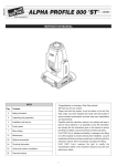
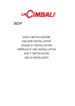
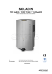
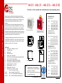
HA121 - HAL121 - HAL121L - HAL121B
Applications and users that have traditionally demanded conventional
electromechanical hooters, sirens, buzzers and bells can now choose the
next generation alternative. The technology used in the Hootronic range
features the latest in amplifier and digital to analogue conversion
technology.
The E2S Hootronic series of products faithfully reproduce the sounds
made by traditional electro-mechanical signalling devices but in a modern,
reliable and cost effective way. With output levels of up to 121dB(A) at 1
metre the Hootronic also surpasses the performance and effectiveness of
its traditional counterpart. Unlike the traditional electro-mechanical devices
the Hootronic range is continuously rated, requires zero maintenance and
signal quality and performance will not degrade with age.
Voltage range and current
consumption for the HA121
Hootronic Alarm Horn:
Voltage:
HA121: Hootronic Alarm Horn
HAL121: Hootronic Alarm Horn
combined with either Xenon,
filament bulb or L.E.D beacon.
115vac
230vac
50/60Hz
50/60Hz
Range:
+/-25%
+/-10%
+/-10%
Current:
375mA
160mA
75mA
Voltage range and current
consumption for the HAL121
Hootronic Alarm with 5J Xenon:
210 ,0 0
19 0,0 0
1 90 ,0 0
Ø9,0 0
1 90 ,0 0
Voltage:
The lightweight, durable housings are manufactured from impact and fire
resistant UL94V0 & 5VA ABS. The unit can also be supplied as combined
unit (the HAL121 version) with either a 5 Joule Xenon, L.E.D or filament
bulb beacon in a choice of up to 7 lens colours.
24vdc
Ø9,0 0
24vdc
115vac
230vac
50/60Hz
50/60Hz
Range:
+/-25%
+/-10%
+/-10%
Current:
645mA
270mA
130mA
210 ,0 0
19 0,0 0
Voltage range and current
consumption for the HAL121L
Hootronic Alarm with L.E.D beacon:
1 90,00
Voltage:
2 74,00
Specifications:
l
Nominal output : 121dB(A) @ 1m +/-3dB
l
3 stage alarm option
l
Volume control
l
300m effective range
l
Voltages : 24vdc; 115vac;230vac
l
HA121: IP55 (up to IP66 dust protected & watertight with WR kit)
l
HAL121: IP55 (up to IP56 with WR kit)
l
Enclosure material : UL94V0 & 5VA rated FR ABS
l
Colour available : Red (RAL3000), Grey (RAL7035)
l
Operating temperature : -25 to +55°C
l
Storage temperature : -40 to +70°C
l
Relative humidity : 90% at 20°C
l
Weight HA121: DC: 2.10Kg AC: 2.70Kg
HAL121: DC: 2.30Kg AC: 2.90Kg
HAL121:
Xenon: 5 Joule @ 1Hz (5 Ws) (60 FPM)
HAL121L:
L.E.D: 8 x L.E.D array (Steady or flashing @ 2Hz).
HAL121B:
Bulb: Filament 3 watt (Steady or flashing @ 1.5Hz).
24vdc
115vac
230vac
50/60Hz
50/60Hz
191 ,5 0
INSTALLATION INSTRUCTIONS
Hootronic: Alarm sounder and combined audio visual signalling device
Range:
+/-25%
+/-10%
+/-10%
Current:
475mA
204mA
102mA
1 84,00
Voltage range and current
consumption for the HAL121L
Hootronic Alarm with Bulb beacon:
All dimen sions are in mil limetres.
NOTE:
l
If applicable please review accompanying
installation instructions for details regarding the
xenon, bulb or L.E.D beacon.
l
Cables for connecting the sounder to the beacon
are supplied with the product.
Voltage:
24vdc
115vac
230vac
50/60Hz
50/60Hz
Range:
+/-25%
+/-10%
+/-10%
Current:
500mA
190mA
90mA
>121dB(A)@1m.
Tel : 0044(0)2087438880 mail : [email protected]
Fax : 0044(0)2087404200 web : www.e2s.com
Mounting and cabling instructions:
Tone Selection:
The unit can be mounted with either the external lugs or by fixing
The Hootronic HA121, HAL121, HAL121L and HAL121B have 5 user selectable ‘traditional’ sounds:
through the back of the housing. For internal fixing the HA121 has
Tone 1
Tone 2
Tone 3
Tone 4
Tone 5
BESA compatible fixing positions marked.
THe HA121 is shipped with one M20 clearance cable entry hole
populated with an IP55 stopping plug. For installations requiring
the cable entry to be through the rear of the unit a M20 clearance
‘knockout’ is located in the centre of the back wall of the housing.
:
:
:
:
:
Industrial Hooter
High Frequency MechanicalSiren
Medium Frequency Mechanical Siren
Electro Mechanical Buzzer
Mechanical Bell
The terminals in the HA121 and HAL121 products will accept from
0.5mm² to 4.0mm² stranded or single core cables.
Each of these sounds has two additional, remotely selectable, alarm s tages as s hown in the table below
(see Fig 2.). The first stage tone is selected by means of the pin headers marked 1,2,3 on the PCBA.
DC units:
AC units:
DC power supply connections should be made to the + and -
AC power supply connections should be made to the L, N and E
terminals.
terminals.
To remotely switch the second and third stage sounds cable into
To remotely switch the second and third stage sounds cable into
the terminals marked ‘S2’ and ‘S3’ respectively. To activate the
the terminals marked ‘C/-’, ‘S2’ and ‘S3’ respectively. To activate
second and third stage sounds switch ‘S2’ or ‘S3’ to the negative
the second and third stage sounds switch ‘S2’ or ‘S3’ to the ‘C/-’
supply whilst the unit is powered (see Fig.1). Stage 2 overides
cable whilst the unit is powered (see Fig.1). Stage 2 overides
stage 1 and stage 3 overides stage 2.
stage 1 and stage 3 overides stage 2.
The Hootronic sounder has the facility to replicate the ‘tail off’
The Hootronic sounder has the facility to replicate the ‘tail off’
traditionally associated with these tone when generated by
traditionally associated with these tone when generated by electro-
electro-mechanical devices. The switching is achieved by cabling
mechanical devices. The switching is achieved by cabling into the
into the terminal marked STOP. The user can remotely activate
terminals marked STOP and ‘C/-’. The user can remotely activate
and de-activate the sounder by switching the connection between
and de-activate the sounder by switching the connection between
the STOP wire and the negative supply line whilst the unit is
STOP and the ‘C/-’ cables whilst the unit is powered. To achieve
powered. To achieve the ‘tail off’ sound at switch off the unit must
the ‘tail off’ sound at switch off the unit must remain powered.
Use the supplied jumper connectors to select the required tone by following the diagrams in the table below
See ‘Mounting and cabling instructions’ for details of how to activate the second and third stages.
remain powered.
Fig. 1
Wiring configuration for 24vdc units.
Fig. 2
Stage1
tone
Alarm
Description
Stage2
(S2)
Stage3
(S3)
Tone 1
Industrial Hooter
Tone 3
Tone 5
3
2
1
Tone 2
High Frequency Mechanical Siren
Tone 1
Tone 5
3
2
1
Tone 3
Medium Frequency Mechanical Siren
Tone 1
Tone 5
3
2
1
Tone 4
Electro Mechanical Buzzer
Tone 1
Tone 5
3
2
1
Tone 5
Mechanical Bell
Tone 1
Tone 2
3
2
1
Header
Wiring configuration for 115, 230vac units.
•Disconnect from pow er source to prev ent electrical shock before installing and serv icing
•Couper l’ alime ntati on pour empêcher tout choc é lectr ique av ant d’effectuer des trav aux d’i nstal lation et
d’e ntreti en.
•Vor der I nstall ation und Wartung v on der Spannungsquel le abnehmen, um e lektri sche S chläge zu v ermeiden.
ATTENTION •Pri ma del l’ins tallaz ione e del la manutenz ione s pegne re l’a limentazione ele ttric a per ev ita re scosse
ele ttric he.
•Des conecte la alimentación par a ev itar de scarga s elé ctrica s antes de la instala ción y mantenimie nto
•Antes de instal ar ou de fa zer a manutenção desligue se mpre da alim entaç ão elé ctrica para ev ita r choques
elé ctric os.
ISN5201-A
No liabil ity i s acce pted f or an y consequen ce of the u se of this d ocume nt. Th e tec hnical spec ificat ion o f this unit is su bject to ch ange withou t noti ce due to o ur pol icy
of contin ual product devel opmen t. All dimen sions are a pproximate. This u nit i s sold subj ect to our standa rd con ditio ns of sale, a cop y of which is ava ilable on
•Str ømmen skal a fbrydes v ed insta lleri ng og efter syn for at undgå elektr isk stød.
•Los koppel en v an de e lektri sche v oeding om e lektri sche schok v óór i nstal latie en onderhoud te v oorkom en.
•Før monte ring e ller v edlik ehold, må spenningen koples fra for å unngå s trømstøt.
•Bryt strömmen innan instal lation och under håll för att förhindra elektriska stöta r stötar.