1
10. Calibration
All 2850 Conductivity/Resistivity Sensor Electronics are factory-calibrated for maximum out-of-the-box accuracy.
The Easy-Cal feature allows calibration to be performed at the sensor.
a.
b.
c.
d.
e.
f.
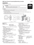
SW2: 4-20 mA output range selection switch bank
Power and 4 to 20 mA or Digital (S3L) output terminal block
SW3 and SW4: Electrode Cell Constant selection switch banks
D3: LED indicator
SW1: Easy-Cal Push-button
Conductivity Electrode connections
CH 2
ON
2
3
2
4
CTS
3
b
1
ON
2
3
CTS
a
4
•
•
CH 1
1
ON
2
c
f
4
3
CTS
1
1
e
SW1
D3
d
10.1 Easy-Cal
Easy-Cal is a single-point calibration system. During this procedure, if the measured value is within ±10% of any of the test values
listed below, the 2850 will automatically recognize the test value and calibrates the output to that value.
Note:
The first step (Reset) is recommended each time an electrode is replaced, but is NOT necessary upon initial installation or periodic
calibration.
1.
Reset the 2850 Sensor to factory calibration: Set all switches on SW3 (and SW4 for dual input) to OPEN. Apply power, wait at
least 3 seconds, then press and hold SW1 until the LED (D3) comes on steady then goes off again (approx. 10 seconds). When
the LED goes off, release SW1; reset is complete. Reset SW3 and SW4 to the proper settings.
2.
Place the electrode/sensor assembly into the conductivity test solution appropriate to your operating range. Shake the electrode to
dislodge any air bubbles visible on the surface of the electrode.
• 146.93 μS, 1408.8 μS, 12856 μS (per ASTM D1125-95)
• 10 μS, 100 μS, 200 μS, 500 μS, 1000 μS, 5000 μS, 10,000 μS, 50,000 μS, 100,000 μS
•
Allow at least 2 minutes for the electrode response to stabilize.
3.
Press and hold SW1 for approximately 8 to 10 seconds. During this time, the LED will come on steady then go back off. (If the
LED blinks several times rapidly, the calibration was not successful. See the troubleshooting section.)
Calibration is complete. Return the system to service.
Calibrating the Dual-channel model 3-2850-63
•
The 2850-63 can only be calibrated if both channels are used, or if channel 2 is disabled.
• To disable channel 2: Set SW4, #4 to OPEN.
•
Place each sensor into a test solution that represents the operating range of that sensor. When SW1 is pressed, the 2850 will
calibrate both channels simultaneously.
•
Dual channel applications usually include one sensor with a smaller cell constant and one sensor with a larger cell constant. Place
the larger cell constant on channel 1. This allows periodic recalibration of the larger cell by simply turning channel 2 OFF.
6
2850 Conductivity/Resistivity Sensor Electronics