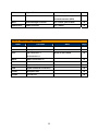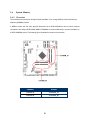
1
MX1900J
Intel® Bay Trail-D Celeron J1900 SoC
Mini iTX Motherboard
User’s Manual
Edition 1.00 – Oct, 2014
1
FCC Statement
THIS DEVICE SUPPORTS PART 15 FCC RULES. OPERATION IS SUBJECT TO THE FOLLOWING TWO
CONDITIONS:
(1) THIS DEVICE MAY NOT CAUSE HARMFUL INTERFERENCE.
(2) THIS DEVICE MUST ACCEPT ANY INTERFERENCE RECEIVED INCLUDING INTERFERENCE THAT MAY CAUSE
UNDESIRED OPERATION.
THIS EQUIPMENT HAS BEEN TESTED AND FOUND TO COMPLY WITH THE LIMITS FOR A CLASS "A" DIGITAL DEVICE,
PURSUANT TO PART 15 OF THE FCC RULES.
THESE LIMITS ARE DESIGNED TO PROVIDE REASONABLE PROTECTION AGAINST HARMFUL INTERFERENCE WHEN THE
EQUIPMENT IS OPERATED IN A COMMERCIAL ENVIRONMENT. THIS EQUIPMENT GENERATES, USES, AND CAN RADIATE
RADIO FREQUENCY ENERGY AND, IF NOT INSTATLLED AND USED IN ACCORDANCE WITH THE INSTRUCTION MANUAL,
MAY CAUSE HARMFUL INTERFERENCE TO RADIO COMMUNICATIONS.
OPERATION OF THIS EQUIPMENT IN A RESIDENTIAL AREA IS LIKELY TO CAUSE HARMFUL INTERFERENCE IN WHICH
CASE THE USER WILL BE REQUIRED TO CORRECT THE INTERFERENCE AT HIS OWN EXPENSE.
Notice
This guide is designed for experienced users to setup the system within the shortest time. For detailed
information, please always refer to the electronic user's manual.
Copyright Notice
Copyright © 2011 BCM Advanced Research, ALL RIGHTS RESERVED.
No part of this document may be reproduced, copied, translated, or transmitted in any form or by any
means, electronic or mechanical, for any purpose, without the prior written permission of the original
manufacturer.
Trademark Acknowledgement
Brand and product names are trademarks or registered trademarks of their respective owners.
2
Disclaimer
BCM Advanced Research reserves the right to make changes, without notice, to any product, including
circuits and/or software described or contained in this manual in order to improve design and/or
performance. BCM Advanced Research assumes no responsibility or liability for the use of the described
product(s), conveys no license or title under any patent, copyright, or masks work rights to these products,
and makes no representations or warranties that these products are free from patent, copyright, or mask
work right infringement, unless otherwise specified. Applications that are described in this manual are for
illustration purposes only. BCM Advanced Research makes no representation or warranty that such
application will be suitable for the specified use without further testing or modification.
Life Support Policy
BCM Advanced Research PRODUCTS ARE NOT FOR USE AS CRITICAL COMPONENTS IN LIFE
SUPPORT DEVICES OR SYSTEMS WITHOUT THE PRIOR WRITTEN APPROVAL OF BCM Advanced
Research.
As used herein:
1. Life support devices or systems are devices or systems which, (a) are intended for surgical implant into
body, or (b) support or sustain life and whose failure to perform, when properly used in accordance with
instructions for use provided in the labeling, can be reasonably expected to result in significant injury to
the user.
2.
A critical component is any component of a life support device or system whose failure to perform can
be reasonably expected to cause the failure of the life support device or system, or to affect its safety
or effectiveness.
3
A Message to the Customer
BCM Customer Services
Each and every BCM product is built to the most exacting specifications to ensure reliable performance in
the harsh and demanding conditions typical of industrial environments. Whether your new BCM device is
destined for the laboratory or the factory floor, you can be assured that your product will provide the
reliability and ease of operation for which the name BCM has come to be known.
Your satisfaction is our primary concern. Here is a guide to BCM customer services. To ensure you get the
full benefit of our services, please follow the instructions below carefully.
Technical Support
We want you to get the maximum performance from your products. So if you run into technical difficulties,
we are here to help. For the most frequently asked questions, you can easily find answers in your product
documentation. These answers are normally a lot more detailed than the ones we can give over the phone.
So please consult the user’s manual first.
To receive the latest version of the user’s manual; please visit our Web site at:
http://www.bcmcom.com.
If you still cannot find the answer, gather all the information or questions that apply to your problem, and
with the product close at hand, call your dealer. Our dealers are well trained and ready to give you the
support you need to get the most from your BCM products. In fact, most problems reported are minor and
are able to be easily solved over the phone.
In addition, free technical support is available from BCM engineers every business day. We are always
ready to give advice on application requirements or specific information on the installation and operation of
any of our products. Please do not hesitate to call or e-mail us.
BCM Advanced Research
11 Chrysler,
Irvine, California, 92618
USA
Tel : +1-949-470-1888
Fax : +1-949-470-0971
http://www.bcmcom.com
E-mail: [email protected]
4
Product Warranty
BCM warrants to you, the original purchaser, that each of its products will be free from defects in materials
and workmanship for two years from the date of purchase.
This warranty does not apply to any products which have been repaired or altered by persons other than
repair personnel authorized by BCM, or which have been subject to misuse, abuse, accident or improper
installation. BCM assumes no liability under the terms of this warranty as a consequence of such events.
Because of BCM high quality-control standards and rigorous testing, most of our customers never need to
use our repair service. If any of BCM products is defective, it will be repaired or replaced at no charge
during the warranty period. For out-of-warranty repairs, you will be billed according to the cost of
replacement materials, service time, and freight. Please consult your dealer for more details. If you think
you have a defective product, follow these steps:
1. Collect all the information about the problem encountered. (For example, CPU type and speed, BCM
products model name, hardware & BIOS revision number, other hardware and software used, etc.)
Note anything abnormal and list any on-screen messages you get when the problem occurs.
2. Call your dealer and describe the problem. Please have your manual, product, and any helpful
information available.
3. If your product is diagnosed as defective, obtain an RMA (return material authorization) number from
your dealer. This allows us to process your good return more quickly.
4. Carefully pack the defective product, a complete Repair and Replacement Order Card and a
photocopy proof of purchase date (such as your sales receipt) in a shippable container. A product
returned without proof of the purchase date is not eligible for warranty service.
Write the RMA number visibly on the outside of the package and ship it prepaid to your dealer.
5
Manual Objectives
This manual describes in detail the BCM MX1900J Main board.
We strongly recommend that you study this manual carefully before attempting to interface with MX1900J
or change the standard configurations. Whilst all the necessary information is available in this manual we
would recommend that unless you are confident, you contact your supplier for guidance.
Please be aware that it is possible to create configurations within the CMOS RAM that make booting
impossible. If this should happen, clear the CMOS settings, (see the description of the Jumper Settings for
details).
If you have any suggestions or find any errors concerning this manual and want to inform us of these,
please contact our Customer Service department with the relevant details.
Safety Precautions
Warning!
Always completely disconnect the power cord from your chassis whenever you
work with the hardware. Do not make connections while the power is on. Sensitive
electronic components can be damaged by sudden power surges. Only
experienced electronics personnel should open the PC chassis.
Caution!
Always ground yourself to remove any static charge before touching the
mainboard. Modern electronic devices are very sensitive to static electric charges.
As a safety precaution, use a grounding wrist strap at all times. Place all electronic
components in a static-dissipative surface or static-shielded bag when they are not
in the chassis.
Document Amendment History
Revision
st
1 (1.00)
Date
Oct, 2014
Comment
Initial Release
6
Contents
Chapter 1: System Setup ..............................................................................................12
1.1
Welcome! ......................................................................................................................................12
1.2
Packing Contents ..........................................................................................................................12
1.3
Special Features ...........................................................................................................................13
1.3.1
Product Overview ..........................................................................................................................13
1.4
Before you proceed.......................................................................................................................15
1.5
Mainboard Overview .....................................................................................................................16
1.5.1
Mounting Holes .............................................................................................................................16
1.5.2
Mainboard Layout .........................................................................................................................17
1.5.3
Layout Content List .......................................................................................................................18
1.5.3.1
Slots ..............................................................................................................................................18
1.5.3.2
Internal Jumpers ...........................................................................................................................18
1.5.3.3
Internal Headers ...........................................................................................................................18
1.5.3.4
Back Panel Connectors ................................................................................................................19
1.6
System Memroy ............................................................................................................................20
1.6.1
Overview .......................................................................................................................................20
1.6.2
Memory Configurations .................................................................................................................21
1.6.3
Installing the DDR3L SODIMM .....................................................................................................22
1.6.4
Removing the DDR3L SODIMM .................................................................................23
1.7
Power Supply ................................................................................................................................24
1.7.1
12V DC-In Power Connector: ATX12V1 .......................................................................................24
1.8
Back Panel ....................................................................................................................................25
1.8.1
Back Panel Connectors ................................................................................................................25
1.9
Connectors/Headers .....................................................................................................................27
1.9.1
Serial ATA 2.0 Connectors: SATA1, SATA2 ................................................................................27
1.9.2
Serial ATA Power Connectors: SATAPW1 ...................................................................................28
1.9.3
CPU & System Fan Connectors: CPU_FAN1, SYS_FAN1 ..........................................................29
1.9.4
Front Panel Audio Connector: AAFP1 ..........................................................................................30
1.9.5
Amplifier Connector: JAMP1 .........................................................................................................30
1.9.6
Front USB2.0 Headers: USB56, USB78.......................................................................................31
1.9.7
Serial Port Connector: COM1 .......................................................................................................31
1.9.8
LPT Port Connector: LPT1............................................................................................................32
1.9.9
Front Panel Connectors: F_PANEL1 ............................................................................................32
1.9.10
Panel Inverter Connection Port: JBKL1 ........................................................................................33
7
1.9.11
LVDS Header: JLVDS1.................................................................................................................33
1.9.12
Digital I/O Connector: JDIO1 ........................................................................................................34
1.9.13
The Header: JPSONLOCK1 .........................................................................................................34
1.10
Jumpers ........................................................................................................................................35
1.10.1
ATX/AT Mode Selection: JPSON1 ................................................................................................35
1.10.2
Clear CMOS Jumper: CLCMOS1 .................................................................................................36
1.10.3
COM1 Ring-In/ +12V/ +5V Select: JCOMPWR1 ..........................................................................37
1.10.4
mSATA Mode Select: JSATA1 .....................................................................................................37
1.11
The Expansion Slots .....................................................................................................................38
1.11.1
Installation of Expansion Card ......................................................................................................38
1.11.2
Setup An Expansion Card.............................................................................................................38
1.11.3
Mini PCI Express Slot: MINI_CARD1, MINI_CARD2 ...................................................................39
Chapter 2: Starting Up the System .............................................................................41
2.1
Starting Up Your System ...............................................................................................................41
Chapter 3: BIOS Setup ..................................................................................................43
3.1
BIOS Falsh Related Procedure ....................................................................................................43
3.2
Introducing BIOS ...........................................................................................................................43
3.3
Entering BIOS Setup Menu...........................................................................................................44
3.4
Getting Help ..................................................................................................................................44
3.5
BIOS Menu Screen .......................................................................................................................45
3.6
Main Menu ....................................................................................................................................46
3.7
Advanced Menu ............................................................................................................................47
3.7.1
ACPI Settings ................................................................................................................................48
3.7.2
Trust Computing ...........................................................................................................................49
3.7.3
CPU Configuration ........................................................................................................................50
3.7.4
SATA Configuration .......................................................................................................................51
3.7.5
Miscellaneous Configuration .........................................................................................................53
3.7.6
CSM Configuration ........................................................................................................................54
3.7.7
PPM Configuration ........................................................................................................................56
3.7.8
TXE Configuration .........................................................................................................................57
3.7.9
Super IO Configuration .................................................................................................................58
3.7.9.1
Serial Port 1 Configuration ............................................................................................................59
3.7.9.2
Parallel Port Configuration ............................................................................................................60
3.7.9.3
Watch Dog Configuration ..............................................................................................................61
3.7.9.4
Digital I/O Configuration ................................................................................................................62
3.7.10
Hardware Monitor .........................................................................................................................63
8
3.7.10.1 Smart Fan Mode Configurtion .......................................................................................................64
3.7.11
USB Configuration ........................................................................................................................66
3.8
Chipset ..........................................................................................................................................68
3.8.1
North Bridge ..................................................................................................................................69
3.8.1.1
Intel IGD onfiguration ....................................................................................................................70
3.8.1.2
Boot Display Control .....................................................................................................................71
3.8.2
South Bridge .................................................................................................................................72
3.8.2.1
Azalia HD Audio ............................................................................................................................73
3.8.2.2
USB Configuration ........................................................................................................................74
3.8.2.3
PCI Express Configuration............................................................................................................75
3.9
Security .........................................................................................................................................77
3.10
Boot ...............................................................................................................................................78
3.11
Save & Exit....................................................................................................................................80
Chapter 4: Application Note ..........................................................................................81
9
Mainboard Specifications
Model
MX1900J
Processor
Intel® Celeron® J1900 Processor onboard 2 GHz (Intel® Bay Trail-D Platform)
Chipset
SoC
Memory
2 x 204Pin SODIMM sockets supports DDR3L memory module (1.35V ONLY) 1333
MHz up to 8GB (4GB maximum/slot)
Display
Intel® Integrated Graphic Engine
Maximum Resolution
VGA: 1920x1200
LVDS: 1920x1200
DP: 2560x1600
SATA
2 x SATA II connectors
Expansion Slots
1x Full Size Mini-PCIe with mSATA Support (Shared one channel with SATA
connector (SATA2)
1 x Half Size Mini-PCIe
USB
4 x USB 2.0 ports (4 @ 2x Headers)
4 x USB 3.0 ports (4 @ Rear I/O)
TPM
1 x TPM 1.2 Security Device (Infineon® TPM Chip 9635)
Super I/O Controller
Nuvoton® NCT6776F
Serial Ports
1 x RS232 ports (1 x header)
LPT
1 x LPT header
Watch Dog Timer
1sec ~ 255 min timer
HW Monitor
Yes
Audio
Realtek® ALC892
HD Audio Codec with auto jack sensing
LAN
Intel® i211-AT PCIe Gigabit LAN
1 x 10/100/1000 LAN
Intel® i211-AT PCIe Gigabit LAN
1 x 10/100/1000 LAN
DIO
8 Bit
BIOS
AMI® BIOS
AMI BIOS with 32Mb SPI ROM
Onboard I/O Headers
SATA
2 x Std. SATAII Connectors
10
USB
2 x USB2.0 Headers (4 ports on headers)
RS232
1 x Headers
LPT
1 x Header
Front Audio
1 x Header
Amplifier
1 x Header
Front Panel
1 x Header
Fan Header
2 x Headers (4-pins)
LVDS
1 x Header
Inverter Connection Port
1 x Header
Onboard Jumpers
COM Port Ring-In/ Power Select
1 x Headers provides Selection of “Ring-In”, or “12V” or “5V” on COM port
AT/ATX Select
1 x Header
Clear CMOS
1 x Header
Back I/O Panel
VGA
1 x DB 15 Connector
DP (DisplayPort)
1 x DP Connector
USB3.0
4x Stack up USB Connector
LAN and USB
2 x RJ45 Connector
Audio
1 x Line-Out
1 x Mic-In
Power
1 x DC 12V Connector
Power & Connector
1 x 4 pin ATX Connector (AC)
1 x DC 12V Connector
Form Factor
uATX 9.6” x 9.6”
11
Chapter 1: System Setup
This chapter describes the mainboard features and the new technologies it supports
1.1
Welcome!
The mainboard delivers a host of new features and latest technologies, making it another line of BCM
long life mainboards! Before you start installing the mainboard, and hardware devices on it, check the
items in your package with the list below.
If any of the items listed below is damaged of missing, please contact with your vendor.
1.2
Packing Contents
• Mainboard
• 1 x MX1900J
• Cable
• 1 x SATA Power Cable
• Accessories
• 1 x MX1900J I/O Shield
12
1.3
Product Highlights
1.3.1
Product Overview
MX1900J is equipped with quad-core Intel® Celeron® desktop J1900 processor (formerly
codenamed BayTrail-D) with speeds of 2.0 GHz delivering outstanding computing, graphical and
media performance in a compact and economically efficient form factor. The J1900 technology is a
22nm, leading-edge, and low-power system-on-a chip (SoC) solution designed based on the 4th
generation Intel® Atom™ E3800 (formerly codenamed Bay Trail-I) platform.
1.3.2
Platform Features and Benefits
• Memory support, integrated low voltage DDR3L memory controller
• Operating system support:
- Microsoft Win7/ Win8/ Win8.1
- Linux (Kernel 12.04 or later)
1.3.3
Key Architecture Features
• Supports Intel quad-core Intel® Celeron® Desktop J1900 processor
- 22nm monolithic die
- Integrated Intel's 7th generation (Gen 7) graphics and media encode/decode engine
- TDP: 10W
• Integrated Display Interfaces
- Display Port
- Analog VGA
- LVDS
• I/O
- PCI Express® Gen 2
- 2 SATAII ports
- High Definition Audio
- USB: Gen 2.0, 4 ports
- Hardware Monitor
- Watchdog timer
13
• Trusted Platform Module (TPM) Support
By combining the onboard TPM 1.2 with TPM security software (provided by the third party), it will enhance
the security level of the system.
• PRECAUTION: When TPM is enabled and utilized through TPM software, there is
possibility that the encrypted data will not be accessible, or recoverable if one of the
following situations occurred:
1. Lost of TPM password.
2. System or board failure, or being replaced.
3. Hard Drive failure.
14
1.4
Before you proceed
Take note of the following precautions before you install mainboard components or change any
mainboard settings.
• Unplug the power cord from the wall socket before touching any component inside the
system.
• Use a grounded wrist strap or touch a safely grounded object or to a metal object, such as the
power supply case, before handling components to avoid damaging them due to static
electricity.
• Hold components by the edges to avoid touching the ICs on them.
• Whenever you uninstall any component, place it on a grounded antistatic pad or in the bag
that came with the component.
• Before you install or remove any component, ensure that the power supply is switched off or
the power cord is detached from the power supply. Failure to do so may cause severe
damage to the mainboard, peripherals, and/or components.
15
1.5
Mainboard Overview
Before you install the mainboard, study the configuration of your chassis to ensure that the mainboard fits
into it.
Make sure to unplug the power cord before installing or removing the mainboard. Failure
to do so can cause you physical injury and damage mainboard components.
1.5.1
Mounting Holes
Place the screws into the mounting holes indicated by red squares to secure the mainboard to the chassis.
Do not over-tighten the screws! Doing so may damage the mainboard.
16
1.5.2
Mainboard Layout
17
1.5.3
Layout Content List
• 1.5.3.1 Slots
Label
SODIMM_A1
Function
Note
240-pin DDR3L SODIMM slot A1
1. If there is only one memory
Page
20
module being installed in the
system, install it on this slot.
SODIMM_B1
240-pin DDR3L SODIMM slot B1
20
MINI_CARD1
Mini PCIe Slot for FULL size card
39
MINI_CARD2
Mini PCIe Slot for HALF size card
39
• 1.5.3.2
Internal Jumpers
Label
Function
Note
Page
CLCMOS1
Clear CMOS
3 x 1 header, pitch 2.54mm
36
JPSON1
AT/ATX Power Select
3 x 1 header, pitch 2.54mm
35
JCOMPWR1
COM1 RI/ +5V/ +12V Select
3 x 2 header, pitch 2.00mm
37
JSATA1
mSATA mode Select
2 x 1 header, pitch 2.00mm
37
• 1.5.3.3
Internal Headers
Label
Function
Note
Page
ATX12V1
DC Power Connector
2 x 2 header
24
CPU_FAN1
CPU Fan Connector
4 x 1 wafer, Pitch 2.54mm
29
SYS_FAN1
System Fan Connector
4 x 1 wafer, Pitch 2.54mm
SATA1,
Serial ATA Connectors 1~2
7-pin header
27
COM1
Serial Port 1
5 x 2 header, pitch 2.00mm
31
LPT1
Parallel Port Connector
13 x 2 header, pitch 2.00mm
32
USB56
USB2.0 Connector
5 x 2 header, pitch 2.54mm
31
F_PANEL
System Panel Connector
5 x 2 header, pitch 2.54mm
32
AAFP1
Front Panel Audio Connector
4 x 1 header, pitch 2.54mm
30
JAMP1
Amplifier Connector
4 x 1 header, pitch 2.54mm
30
SATA2,
USB78
18
JDIO1
Digital I/O Connector
6 x 2 header, pitch 2.00mm
34
JLVDS1
LVDS Panel Connector
20 x 2 header, 1.25mm pitch wire
33
to board connector (WTB)
JBKL1
Panel Backlight Connector
5 x 1 header, pitch 2.00mm
33
JPSONLOCK1
PSON Connector
2 x 1 header
34
• 1.5.3.4 Back Panel Connectors
Label
Function
DC1
DC Adapter Connector
DP1
Display Port
VGA1
VGA Connector x 1
Note
Page
DC 12V
25
D-sub 15-pins, female
25
DVI Connector x 1
USB12
USB3.0 Connectors x 2
25
USB34
USB3.0 Connectors x 2
25
LAN1
Gigabit LAN RJ-45 Connector x 1
25, 26
LAN2
Gigabit LAN RJ-45 Connector x 1
25
AUDIO1
Microphone Port
26
AUDIO2
Line-out Port
26
19
1.6
1.6.1
System Memory
Overview
The mainboard comes with two 204-pin Double Data Rate 3 Low voltage (DDR3L) Dual Inline Memory
Modules (SODIMM) sockets.
A DDR3L module has the same physical dimensions as a DDR SODIMM but has a 204-pin footprint
compared to the 240-pin DDR2 DIMM. DDR3L SODIMMs are notched differently to prevent installation on
a DDR2 SODIMM socket. The following figure illustrates the location of the sockets:
Channel
Socket
Channel A
SODIMM_A1
Channel B
SODIMM_B1
20
1.6.2 Memory Configurations
You may ONLY install 1GB, 2GB, or 4GB DDR3L-1333MHz (PC3-10600); Non-ECC, Un-buffered 1.35V
DDR3L memory modules on this board (4GB maximum for each slot). MX1900J does not support DDR/
DDR2/ DDR3 SODIMM modules, DO NOT install DDR/ DDR2/ DDR3 SODIMM modules on this board.
• When there is only one DDR3L memory module to be installed, install it on
“SODIMM_A1” slot ONLY.
• In dual-channel configurations, install only identical (same type, same size)
DDR3L memory modules; one installed at socket “SODIMM_A1”, the other installed
at socket “SODIMM_B1”.
• Always install DIMMs with the same CAS latency. For optimum compatibility, it is
recommended that you obtain the exact same model (and same batch) of memory
modules from the same vendor.
21
1.6.3
Installing the DDR3L SODIMM
Make sure to unplug the power supply before adding or removing SODIMMs or other
peripherals from the system. Failure to do so may cause severe damage to both the
mainboard and the peripherals.
1. Locate the SODIMM socket onboard.
2. Hold two edges of the SODIMM module carefully, and keep away of touching its connectors.
3. Align the notch key on the SODIMM module with the rib on the slot.
4. Firmly press the SODIMM module into the socket which will be snapped into the mounting notch
automatically. Do not force the SODIMM module in with extra force as the SODIMM module can
only fits in one direction.
1. A DDR3L memory module is keyed with a notch so that it fits in only one
direction.
2. DO NOT force the memory module into the socket in order to avoid damaging the
memory module and the slot.
3. DDR3L memory modules are not interchangeable with DDR or DDR2, or DDR3.
4. DDR3L standard IS NOT backward compatible. You shall only install the DDR3L
memory modules on this mainboard.
22
1.6.4
Removing the DDR3L SODIMM
Follow these steps to remove a SODIMM.
1.
Press the two ejector tables on the slot outward simultaneously
2.
Remove the SODIMM module from the socket.
Hold the SODIMM module gently when pressing the ejector tabs. The SODIMM might
get damaged when it flips out with extra force.
23
1.7
1.7.1
Power Supply
12V DC-In
Power Connector:
ATX12V1
This connector is for ATX power supply plug (ATX12V1), The power supply plug is designed to fit
the connector in only one orientation. Find the proper orientation and push down firmly until the
connector is completely fit. In order to power on MX1900J through this connector, the signal
“PSON” must be connected with the “GND” signal on the 20/24 pin ATX power connector.
1.
It is recommended that you use a ATX power supply unit (PSU) that complies with
ATX 12V specification 2.0 (or later version) and provides a minimum power of
300W.
2.
Use of a PSU with a higher power output is recommended when configuring a
system with more power-consuming devices. The system may become unstable or
may not boot if the power supply is inadequate.
3.
The MX1900J board can be power on EITHER through:
A. Use 4-pin ATX power connector from ATX power supply and connect it to
“ATX12V1” header.
B. Use an AC power adapter and connect it to “DC1” connector on the rear I/O of
MX1900J board (AC Power Adapter Output: 12.0V/5.0A).
24
1.8
1.8.1
Back Panel
Back Panel Connectors
Item
Name
Function
1
DC1
AC Power
Adapter
Description
The port is for an AC power adapter (DC Output
12.0V/5.0A).
Connector
2
DP1
Display Port
The display port Connector
3
VGA1
VGA Video Port
The VGA15-pin Connector.
4
USB34
USB 3.0
Connectors
5
6.
USB12
LAN2.
USB 3.0
These two 4-pin Universal Serial Bus (USB) ports
are available for connecting USB 3.0 devices.
These two 4-pin Universal Serial Bus (USB) ports
Connectors
are available for connecting USB 3.0 devices.
Gigabit LAN
This port allows Gigabit connection to a Local Area
(RJ-45)
Connectors
Network (LAN) through a network hub. Refer to
the table below for the LAN port LED indications.
ACT/Link LED
Speed LED
Status
Description
Status
Description
OFF
No link
OFF
10Mbps
connection
Orange
Linked
Green
100Mbps
connection
Blinking
Data
activity
7
LAN1
Gigabit LAN
(RJ-45)
Connectors
Orange
1Gbps
connection
This port allows Gigabit connection to a Local Area
Network (LAN) through a network hub. Refer to
the table below for the LAN port LED indications.
ACT/Link LED
25
Speed LED
Status
Description
Status
Description
OFF
No link
OFF
10Mbps
connection
Orange
Linked
Green
100Mbps
connection
Blinking
Data
Orange
activity
8
AUDIO2
Microphone port
1Gbps
connection
This port connects a microphone.
(Pink)
9
AUDIO1
Line-out port
This port connects a headphone or a speaker.
(Lime)
26
1.9
1.9.1
Connectors/ Headers
Serial ATA 2.0 Connectors: SATA1,
SATA2
SATA ports “SATA1” and “SATA2” support SATA2.0 standard.
1.
Due to “SATA2” and “MINI_CARD1 (mSATA) are sharing the same SATA channel,
only either one of them can be used. Please DO NOT install devices to these two
headers at the same time.
2.
Please do not fold the Serial ATA cable into 90-degree angle. Otherwise, data loss
may occur during data transmission.
27
1.9.2
Serial ATA Power Connector: SATAPW1
This connector provides power connection to SATA device.
28
1.9.3
CPU & System Fan Connectors:
CPU_FAN1,
SYS_FAN1
The fan power connectors support system cooling fan with +12V. When connecting the wire to these fan
connectors, please note that the red wire is designated as “Power” and should be connected to “+12V” pin;
the black wire is designated as “Ground” and should be connected to “GND”. In order to take the advantage
of System Hardware Monitor and Smartfan feature, be sure to use the fan which is specifically designed
with speed sensor.
In order for MX1900J board to function properly, it is recommended to maintain air
flow around MX1900J with ambient temperature not to exceed 33.4oC.
29
1.9.4
Front Panel Audio Connector:
AAFP1
This connector is prepared for a chassis-mounted front panel audio I/O module that supports HD Audio
standard. Connect one end of the front panel audio I/O module cable to this connector.
2
1
10. LINE2-JD
8. NC
6. MIC2-JD
4. +3.3
2. GND
1.9.5
9. LINE2L
7. SENSEB
5. LINE2R
3. MIC2R
1. MIC2L
Amplifier Connector: JAMP1
This header provided amplified audio signals to external speakers (2-channels). The dB level can be
adjusted under BIOS.
1
30
1.9.6
Front USB2.0 Headers:
USB56,
USB78
Be sure the pins of VCC and GND signals are connected to the USB2.0 headers
correctly. Otherwise, it may cause damage to the USB port and/or the connected USB
device.
1.9.7
Serial Port Connector:
COM1
31
1.9.8
LPT Port Connector:
LPT1
LPT1
1. LPT_STB#
3. LPT_PD0
5. LPT_PD1
7. LPT_PD2
9. LPT_PD3
11. LPT_PD4
13. LPT_PD5
15. LPT_PD6
17. LPT_PD7
19. LPT_ACK#
21. LPT_BUSY
23. LPT_PE
25. LPT_SLCT
1.9.9
Front Panel Connectors:
2. LPT_AFD#
4. LPT_ERR#
6. LPT_INIT#
8. LPT_SLIN#
10. GND
12. GND
14. GND
16. GND
18. GND
20. GND
22. GND
24. GND
26. NC
F_PANEL1
These connectors are for electrical connections to the front panel switches and LEDs. The “F_PANEL1”
connector is compliant with Intel® Front Panel I/O Connectivity Design Guide.
32
1.9.10
Panel Inverter Connection Port:
1.9.11
LVDS Header:
JLVDS1
33
JBKL1
1.9.12
Digital I/O Connector:
JDIO1
This header provides 8-bit general purpose I/O (GPIO) connections to external device. Customer can write
their own monitoring program to monitor the status of external device connected with this header.
1.9.13
The Header:
JPSONLOCK1
This header is reserved for factory internal use only.
34
1.10 Jumpers
1.10.1
ATX/AT Mode Selection: JPSON1
This header provides the option to boot the system in the form of ATX mode (default) or AT mode.
When the system is set in AT mode, the system power on/off will be controlled directly by the power
switchon power supply. And some of the power saving modes will not function as ATX mode provided.
35
1.10.2
Clear CMOS Jumper:
CLCMOS1
There is a CMOS RAM onboard that has the power supplied from an external battery to maintain the
registry settings of system configuration.
For normal state (default), the jumper is set on pin location 1 and 2.
To clear the CMOS, disconnect all power connections to MX1900J first, then set the CLCMOS1 jumper to
pin location 2 and 3 for at least 30 seconds while the system is off.
1. You can clear CMOS by shorting pin 2-3 for at least 30 seconds (while the system is
OFF), then place the jumper back to pin 1-2 for normal operation.
2. Avoid clearing the CMOS while the system is ON; this may damage the mainboard.
36
1.10.3
COM1 Ring-In/ +12V/ +5V Select: JCOMPWR1
Ring (Default)
+12V
+5V
1.10.4 mSATA Mode Select: JSATA1
Remove this jumper only when there is trouble for BIOS to detect the installed mSATA device on
connector “MINI_CARD1”.
Auto mode
(Default)
Force mSATA
37
1.11 The Expansion Slots
In the future, you may need to install expansion cards. The following sub-sections describe the
expansion slots and the expansion cards that they support.
Make sure to unplug the power cord before adding or removing expansion cards.
Fail to do so may cause injury and damage mainrboard
1.11.1
Installation of Expansion Card
To install an expansion Card:
1. Before install the expansion card, read the documentation that came with it and make the necessary
hardware setting for the card.
2. Remove the chassis cover (if the mainboard is installed in a chassis).
3. Remove the expansion slot bracket from the chassis on the slot that you intend to use. Keep the screw
for later use.
4. Align the card connector with the slot and press it firmly until the card is completely seated on the slot.
5. Secure the card to the chassis with the screw that have been removed earlier (in step 3).
6. Place the chassis cover back on.
1.11.2
Setup An Expansion Card
After installing the expansion card, configure it by adjusting the software settings.
1. Turn on the system and change the BIOS settings if necessary. See Chapter 2 for information on BIOS
setup.
2. Assign an IRQ to the card if necessary.
3. Install the software drivers for the expansion card.
38
1.11.3
Mini PCI Express Slot: MINI_CARD1, MINI_CARD2
The mini PCI express slot supports Mini cards for Wifi, Bluetooth, COM, USB modules, and other cards
that comply with the mini card rev. 1.2 specifications.
For example, the full size mSATA card that can be installed on a miniPCI express slot “MINI_CARD1”.
The half size wifi card can be installed on the miniPCI express slot “MINI_CARD2”.
39
1. Due to the “SATA2” port is sharing the same SATA channel with miniPCI slot
“MINI_CARD1”, only either one of them can be use. DO NOT use the “SATA2” port
and “MINI_CARD1” slot at the same time.
2. When adding or removing expansion cards, make sure the system power is OFF.
3. After the card is installed on the system, make the adjustments under system BIOS
if necessary, then install the card driver provided by the card vendor under system
OS.
4. When using PCI cards on shared slots, ensure that the card driver support “Share
IRQ” or the PCI cards do not need IRQ assignments. Otherwise, conflicts will arise
between the two PCI groups; marking the system unstable and the card inoperable.
40
Chapter 2: Starting Up the System
2.1
Starting Up Your System
1.
After all connections are made, close your computer case cover.
2.
Be sure all the switches are off, and check that the power supply input voltage is set to the local
voltage, usually in-put voltage is 220V∼240V or 110V∼120V depending on your country’s voltage used.
3.
Connect the power supply cord into the power supply located on the back of your system case
according to your system user’s manual.
4.
Turn on your peripheral in following order:
a.
Your monitor.
b.
Other external peripheral (Printer, Scanner, External Modem etc…)
c.
Your system power. For ATX power supplies, you need to turn on the power supply and press
the ATX power switch on the front side of the case.
5.
The power LED on the front panel of the system case will light. The LED on the monitor may light up
or switch between orange and green after the system is on. If it complies with green standards or if it
is has a power standby feature. The system will then run power-on test. While the test are running,
the BIOS will alarm beeps or additional message will appear on the screen.
If you do not see any thing within 30 seconds from the time you turn on the power. The system may
have failed on power-on test. Recheck your jumper settings and connections or call your retailer for
assistance.
Beep
Meaning
One short beep when displaying logo
No error during POST
Long beeps in an endless loop
No DRAM install or detected
One long beep followed by three short
Video card not found or video card memory bad
beeps
High frequency beeps when system is
CPU overheated
working
System running at a lower frequency
6.
During power-on, press <Del> key to enter BIOS setup. Follow the instructions in BIOS SETUP.
7.
If you wish to boot from a different bootable device other than the default arrangement under the BIOS,
you may press <F11> key during the system power-on (post); a menu with all detected bootable
devices which are attached to the system will be displayed. Then you may select the desired first
bootable device from this menu.
41
8.
Power off your computer: You must first exit or shut down your operating system before switch off
the power switch. If you use Windows Operating Systems, click “Start” button, click “Shut down” and
then click “Shut down the computer” The power supply should turn off after windows shut down.
42
Chapter 3: BIOS Setup
3.1
BIOS Flash Related Procedure
1. After the BIOS is flashed, shut down the system.
2. Disconnect all power connections from power supply to the mainboard.
3. Clear the CMOS (For at least 30 seconds).
4. Reconnect all power connections from power supply to the mainboard.
5. When the system is booting at first time after the new BIOS is flashed, it is recommended to
enter the BIOS; load the option “Load Optimized Defaults”, and then “Save and Exit Setup”.
IF ANY OF THE ABOVE STEPS IS NOT FOLLOWED, IT MAY CAUSE THE FLASHED BIOS
NOT FUNCTION PROPERLY.
3.2
Introducing BIOS
The BIOS is a program located on a Flash Memory on the motherboard. This program is a bridge
between motherboard and operating system. When you start the computer, the BIOS program gains
control. The BIOS first operates an auto-diagnostic test called POST (power on self test) for all the
necessary hardware, it detects the entire hardware device and configures the parameters of the hardware
synchronization.
Only when these tasks are completed done it gives up control of the computer to
operating system (OS). Since the BIOS is the only channel for hardware and software to communicate, it
is the key factor for system stability, and in ensuring that your system performance as its best.
In the BIOS Setup main menu of Figure 3-1, you can see several options. We will explain these options
step by step in the following pages of this chapter, but let us first see a short description of the function keys
you may use here:
•
Press <Esc> to quit the BIOS Setup.
•
Press ↑ ↓ ← → (up, down, left, right) to choose, in the main menu, the option you want to confirm or to
modify.
•
Press <F10> when you have completed the setup of BIOS parameters to save these parameters and
to exit the BIOS Setup menu.
•
Press Page Up/Page Down or +/– keys when you want to modify the BIOS parameters for the active
option.
43
3.3
Entering BIOS Setup Menu
Power on the computer and by pressing <DEL> immediately allows you to enter BIOS Setup Menu.
If you are not able to enter the BIOS menu but you still wish to enter Setup, restart the system to try again
by turning it OFF then ON or pressing the “RESET” button on the system case. You may also restart by
simultaneously pressing <Ctrl>, <Alt> and <Delete> keys.
The items under each BIOS category described in this chapter are under continuous
update for better system performance. Therefore, the description may be slightly
different from the latest BIOS and should be held for reference only.
3.4
Getting Help
Main Menu
The main menu lists the setup functions you can make changes to. You can use the arrow keys to select
the item. The on-line description of the highlighted setup function is displayed at the bottom of the screen.
Sub- Menu
If you find a right pointer symbol (as shown in the picture below) appears to the left of certain fields that
means a sub-menu can be launched from this field. A sub-menu contains additional options for a field
parameter. You can use arrow keys to highlight the field and press <Enter> to call up the sub-menu. Then
you can use the control keys to enter values and move from field to field within a sub-menu. If you want to
return to the main menu, just press the <ESC>.
General Help <F1>
The BIOS setup program provides a General Help screen. You can call up this screen from any menu by
simply pressing <F1>. The Help screen lists the appropriate keys to use and the possible selections for the
highlighted item. Press <Esc> to exit the Help screen.
44
3.5
BIOS Menu Screen
When entering the BIOS, the following screen appears. The BIOS menu screen displays the items that
allow user to make changes to the system configuration. To access the menu items, press the
up/down/right/left arrow key on the keyboard until the desired item is highlighted, then press [Enter] to
access the specific menu.
45
3.6
Main Menu
This menu gives user an overview of the general system specifications, such as time, date etc.
• BIOS Information
Displays the auto-detected BIOS information.
• System Date
The date format is <Date>,<Month>,<Day>,<Year>.
• System Time
The time format is <Hour>,<Minute>,<Second>.
46
3.7
Advanced Menu
Select the “Advanced” tab from the BIOS menu screen to enter the Advanced BIOS Setup screen.
NOTE: Take caution when change the settings of the Advanced menu items.
Incorrect field values can cause the system not to function properly.
47
3.7.1
ACPI Settings
• ACPI Sleep State [S3 (suspend to RAM)]
Select the highest ACPI sleep state the system will enter when the system entered suspend state.
Configuration options: [Suspend Disabled], [S3 (suspend to RAM )]
• Wake On LAN Control on S5 [Disable]
Enable /Disable WOL function under ACPI S5 State.
Configuration options: [Disabled], [Enabled]
• Resume On RTC Alarm [Disabled]
Enable or disable system wake on alarm event. When enabled, system will wake upon the hr/min/sec
specified.
Configuration options: [Disabled], [Enabled]
48
3.7.2
Trusted Computing
Trusted computing (TPM) settings.
• Security Deice Support [Disabled]
Enable or disable TPM support.
Configuration options: [Disabled], [Enabled]
• Current Status Information
Displays the TPM status information [SUPPORT TURNED OFF]
49
3.7.3
CPU Configuration
• CPU configuration
Displays the CPU information
• Intel Virtualization Technology [Enabled]
When enable, a VMM can utilize the additional hardware capabilities provided by Virtualization
Technology.
Configuration options: [Disabled], [Enabled]
• Burst Mode [Enabled]
Enable/ Disable Intel® Burt Mode.
Configuration options: [Disabled], [Enabled]
50
3.7.4
SATA Configuration
• SATA Controller(s) [Enabled]
Enable/ Disable Serial ATA Controller.
Configuration options: [Disabled], [Enabled]
• SATA Mode [IDE Mode]
Support IDE, AHCI modes
Configuration options: [IDE Mode], [AHCI Mode]
• Serial ATA Port 1 [Enabled]
Enable/ Disable Serial ATA Port 1
Configuration options: [Disabled], [Enabled]
51
• Serial ATA Port 1 [Enabled]
Enable/ Disable Serial ATA Port 1
Configuration options: [Disabled], [Enabled]
52
3.7.5
Miscellaneous Configuration
Set the optimized BIOS settings by selecting the intended to be installed Windows OS.
• OS Selection [Windows 7]
Optimized BIOS Setting for Windows 8.x or Windows 7.
Configuration options : [Windows 8.X], [Windows 7]
53
3.7.6
CSM Configuration
• CSMSupport [Enabled]
Enable/ Disable Compatibility Support Module Configuration.
Configuration options: [Disabled], [Enabled]
• Network [Legacy only]
Controls the execution of UEFI or Legacy PXE OpROM.
Configuration options: [Legacy only], [UEFI only], [Do not launch]
• Storage [Do not launch]
Controls the execution of UEFI or Legacy Storage OpROM
Configuration option: [Legacy only], [UEFI only], [Do not launch]
• Video [Legacy only]
Controls the execution of UEFI or Legacy Video OpROM
Configuration option: [Legacy only], [UEFI only], [Do not launch]
54
• Other PCI devices [UEFI only]
Determines OpROM execution policy for devices other than Network, Storage, or Video
Configuration option: [Legacy only], [UEFI only]
55
3.7.7
PPM Configuration
• CPU C State Report [Enabled]
Enable/ Disable CPU C state report to OS.
Configuration options: [Disabled], [Enabled]
• Max CPU C-state [C1]
This option controls Max C state that the processor will support.
Configuration options: [C7], [C6], [C1]
56
3.7.8
TXE Configuration
• AFUDOS 8MB (ME) BIOS Flash [Disabled]
Enable this option when update the BIOS through AFUDOS utility with 8MB version BIOS.
Configuration options: [Disabled], [Enabled]
57
3.7.9
Super IO Configuration
• Dep Sleep Function [Disabled]
Select to enable/ disable Deep Sleep S5 function. When selected the enabled option, only the power
button can power on the system.
Configuration options: [Disabled], [Enabled]
58
3.7.9.1
Serial Port 1 Configuration
• Serial Port [Enabled]
Enable or Disable Serial Port (COM).
Configuration options: [Disabled], [Enabled]
• Device Setting [IO=3F8h; IRQ=4]
• Change Setting [Auto]
Select an optimal setting for Super IO device.
Configuration options: [Auto], [IO=3F8h; IRQ=4], [IO=3F8h; IRQ=3, 4, 5, 6, 7, 9, 10, 11, 12], [IO=2F8h;
IRQ= 3, 4, 5, 6, 7, 9, 10, 11, 12], [IO= 3E8h; IRQ= 3, 4, 5, 6, 7, 9, 10, 11, 12], [IO= 2E8h; IRQ= 3, 4, 5, 6, 7,
9, 10, 11, 12]
59
3.7.9.2
Parallel Port Configuration
• Parallel Port [Enable]
Use this item to enable or disable the onboard parallel port.
Configuration options: [Disabled], [Enabled]
• Change Settings [Auto]
Use this item to select an optional setting for Super IO device.
Configuration Options :
[Auto], [IO=378h; IRQ=7], [IO=378h; IRQ=5,6,7,9,10,11,12], [IO=278h;
IRQ=5,6,7,9,10,11,12], [IO=3BCh; IRQ=5,6,7,9,10,11,12]
• Device Mode [STD Printer Mode]
Use this item to change the Printer Port mode.
Configuration Options: [STD Printer Mode], [SPP Mode], [EPP-1.9 and SPP Mode], [EPP-1.7 and SPP
Mode], [ECP Mode], [ECP Mode and EPP-1.9 Mode], [ECP Mode and EPP-1.7 Mode]
60
3.7.9.3
Watch Dog Configuration
• Watch Dog Count Mode [Second(s) Mode]
Select Watch Dog Count Mode
Configuration options: [Second(s) Mode], [Minute(s) Mode]
• Watch Dog Time-out Value [0]
Timer will start to count from end of Post. 00-Timeout Disable
61
3.7.9.4
Digital I/O Configurtaion
• Digital I/O Control [Disabled]
Enabled/ Disabled Digital I/O Control
Configuration options: [Disabled], [Enabled]
62
3.7.10
Hardware Monitor
Display system health status
63
3.7.10.1
Smart Fan Mode Configuration
•System Smart Fan Target [Enabled]
Set to Enable/ Disable system Smart Fan.
Configuration options: [Disabled], [Enabled]
Once enabled, the available configuration options for minimum system fan speed: [Disabled], [12.5%],
[25%], [37.5%], [50%], [62.5%], [75%], [87.5%]
• CPU Smart Fan Function [Enabled]
Set to Enable/ Disable CPU Smart Fan.
Configuration options: [Disabled], [Enabled]
• CPU Smart Fan Target [50C]
Set CPU Smart Fan Target Temperature
Configuration options: [40C], [45C], [50C], [55C], [60C], [65C], [70C]
64
• CPU MIN. Fan Speed (%) [62.5%]
CPU Smart Fan minimum speed settings.
Configuration options: [12.5%], [25%]. [37.5%], [50%], [62.5%], [75%], [87.5%]
1. In order to take the advantage of the smart fan feature, the fan installed must have
4-pin type connector. The 3-pin type connector can only run the installed fan at
maximum speed.
2. Some of the low speed fan might have very low fan speed when set the smart fan
feature at lower speed (for example, set it at 12.5% or 25%). In some cases, the HW
monitor may not be able to track the fan speed and show its speed as 0. You may try
to increase the smart fan speed if run into the situation like this.
65
3.7.11
USB Configuration
USB Configuration Parameters
• USB Device
Display how many USB devices are connected
• Legacy USB Support [Enabled]
Enables legacy USB support. The “Auto” option disabled legacy support if no USB device is connected.
The “Disabled” option will keep USB devices available only for EFI applications.
Configuration options: [Enabled], [Disabled], [Auto]
• XHCI Hand-off [Enabled]
This is a wrokaround for the OS without XHCI hand-off support. The XHCI ownership change should be
claimed by XHCI driver.
Configuraiton options : [Enabled], [Disabled]
66
• EHCI Hand-off [Enabled]
This is a wrokaround for the OS without EHCI hand-off support. The EHCI ownership change should be
claimed by EHCI driver.
Configuraiton options : [Enabled], [Disabled]
67
3.8
Chipset
68
3.8.1
North Bridge
• Dsplay Memory Information
69
3.8.1.1
Intel IGD Configuration
• IG Turbo Enable [Enabled]
Enable/Disable IGD Turbo
Configuration options: [Disabled], [Enabled]
• DVMT Pre-Allocated [64M]
Select DVMT 5.0 Pre-Allocated (Fixed) graphics memory size used by the internal graphics device.
Configuration options: [64M]~ [512M]
• DVMT Total Graphics Mem [256M]
Select DVMT 5.0 total graphics memory size used by the internal graphics device.
Configuration options: [128M], [256M], [MAX]
70
3.8.1.2
Boot Display Control
• Boot Display Selection [VBIOS Default]
Select the video device which will be activated during system post. This feature will be disabled
automatically if an external graphic card is installed.
Configuration options: [VBIOS Default], [CRT], [Display port], [eDP/LVDS]
• Enable LVDS Controller [Disabled]
Enable/Disable Chrontel CH7511B
Configuration options: [Disabled], [Enabled]
• LCD Panel Type [VBIOS Default]
Select LCD panel resolution.
• LCD Brightness Control [30]
Configuration options [1]~[63]
71
3.8.2
South Bridge
• Restore AC Powre Loss [Always OFF]
Select the AC power state when power is re-applied after a power failure.
Configuration options: [Always OFF], [Always ON], [Last State]
1. If the option “Always ON” is planning to be used, instead of using this option
under BIOS, it is recommended to set the jumper switch “JPSON1” to “AT” mode.
This will emulate the system power on/off like using an AT type power supply, which
will turn on the system when there is power connection to the power supply. And
turn-off the system once the power connection to the power supply is removed.
72
3.8.2.1
Azalia HD Audio
• Audio Controller [Enabled]
Control detectionof the Azalia device.
Configuration options: [Enabled], [Disabled]
• Amplifier GAIN (db) [12dB]
Select Amplifier GAIN value.
Configuration options: [6dB], [12dB], [18dB], [24dB]
• Azalia HDMI Codec [Enabled]
Enable/ Disable internal HDMI codec for Azalia.
Configuration options: [Enable], [Disabled]
73
3.8.2.2
USB Configuration
• US3.0 (XHCI) Support [Auto]
Control the USB XHCI (USB3.0) functions.
Configuration options: [Disabled], [Enabled], [Auto]
• USB2.0 (EHCI) Support [Disabled]
Control the USB EHCI (USB2.0) functions.
Configuration options: [Disabled], [Enabled], [Auto]
74
3.8.2.3
PCI Express Configuration
• PCI xpress Port 1 [Enabled]
Enable/ Disable Mini PCIe card 1 controller (control the “MINI_CARD1” slot).
Configuration options: [Disabled], [Enabled]
• Speed [Auto]
Configure PCIe port speed of Mini PCIe card 1 controller
Configuration options: [Auto], [Gen 2], [Gen1]
• Onboard LAN Controller 1 [Enable]
Enable/ Disable LAN1 Controller.
Configuration options: [Disabled], [Enabled]
75
• LAN Option ROM [Disabled]
Enable/ Disable LAN1 PXE option ROM.
Configuration options: [Disabled], [Enabled]
• Onboard LAN Controller 2 [Enable]
Enable/ Disable LAN2 Controller.
Configuration options: [Disabled], [Enabled]
• LAN Option ROM [Disabled]
Enable/ Disable LAN2 PXE option ROM.
Configuration options: [Disabled], [Enabled]
• PCI Express Port 4 [Enabled]
Enable/ Disable Mini PCIe card 2 controller (control the “MINI_CARD2” slot).
Configuration options: [Disabled], [Enabled]
• Speed [Auto]
Configure PCIe port speed of Mini PCIe card 2 controller
Configuration options: [Auto], [Gen 2], [Gen1]
76
3.9
Security
• dministrator Password
Setup Administrator Password
• User Password
Setup User Password
77
3.10
Boot
Boot Configuration
• Setu Prompt Timeout [3]
Number of seconds to wait during system post.
• Bootup NumLock State [On]
Select the keyboard NumLock state
Configuration options: [On], [Off]
• Customer Logo [Disabled]
If a customer logo is added to the BIOS, this option will enable/ disable the display of customer logo during
system post.
Configuration options: [Disabled], [Enabled]
78
• Fast Boot [Disabled]
Enable/ Disable boot with initialization of minimal set of devices required to launch active boot options. Hs
no effect for BBS boot options.
Configuration options: [Disabled], [Enabled]
• Boot mode select [LEGACY]
Select boot mode LEGACY/UEFI
Configuration options: [LEGACY], [UEFI]
• Fixed Boot Order Priorities
Select the system boot order.
79
3.11 Save & Exit
• Save changes and Exit
Exit system setup after saving the changes.
• Discard changes and Exit
Exit system setup without saving the changes.
• Save changes and Reset
Reset system setup after saving the changes.
• Load Optimized Defaults
Restore/Load default values for all the setup option.
80
Chapter 4: Application Note
Please read the following application notes before proceed with the system setup and/or OS
installation:
1.
Due to “SATA2” and “MINI_CARD1” are sharing the same SATA channel, only either one of
them can be used. Please DO NOT install devices to these two headers at the same time.
2.
If there is only one memory module being installed, install it at memory slot “SODIMM_A1”
only.
3.
Due to there is no active cooling mechanism on MX1900J board, it is recommended to
maintain the air flow around the MX1900J board at 33.4oC or below.
4.
If “Win7+SP1” is going to be installed, it is recommended to set the BIOS option
“Miscellaneous Configuration” to “Windows 7”.
5.
If “Win8.x” is going to be installed, it is recommended to set the BIOS option “Miscellaneous
Configuration” to “Win8.X”.
6.
If “Linux” is going to be installed, it is recommended to download the latest kernel (12.04 or
later), the native driver in the kernel should be able to support the LANs, graphic features.
7.
Please install the MX1900J drivers (available from BCM website: www.bcmcom.com, under
“Support” section) for the following OS:
a.
Windows 7+SP1
1.
Intel inf
2.
Intel Graphic
3.
Intel LAN
4.
Realtek Audio
5.
Intel TXE base driver
6.
Intel TXE update driver
7.
Intel USB3.0 driver (Intel recommended to copy the file to system hard drive first,
then install driver from there).
b.
Win8.x
1.
Intel inf
2.
Intel Graphic
3.
Intel LAN
4.
Realtek Audio
5.
Intel TXE base driver
6.
Intel MEI driver (shown as “unknown device” under Device Manager)
81