1
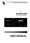
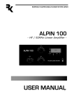
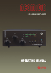
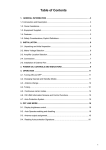
- G2 - when illuminated, a screen-grid overload condition exists; reduce the drive power and/or refresh
the tuning (Section 4-5) for safe operation;
- IP - when illuminated, a plate current overload condition exists; reduce the drive power and/or refresh
the tuning (Section 4-5) for safe operation;
- F – when illuminated, the amplifier automatic protection has tripped. If F is accompanied with one of
the G1, G2, or IP condition indicators, the cause of the protection trip will be evident. When F alone is
illuminated, check the keying wiring, Section 2-4(d). See Section 4-6 for details about the auto-protection
system.
4. OPERATION
Operation of the amplifier is simplified through ACOM’s innovative TRI tuning aid, Auto-Operate function,
and automatic protection systems. To make full use of the amplifier’s potential and to configure it to
local conditions, the following information should be read carefully.
4-1. Turning ON and OFF
In order to turn on the amplifier, press the power switch ON at the bottom-right corner of the front
panel. The LED indicator above the switch will glow green and the audible cooling fan will start. Following
a series of automatic self-tests, the OPER LED will begin to flash green and will continue to do so during
the 150-second warm-up period. Throughout this period, the amplifier will remain in the standby mode,
and the transceiver may continue to be used. Also during this period, the A1-A2 button may be pressed
to change antennas, i.e., between the antennas connected to the ANT1 and ANT2 terminals on the rear
panel of the amplifier. Switching between the antennas does not affect the warm-up process.
CAUTION
To avoid damage not covered under warranty, do not change the antenna output
during a transmission, i.e., never press the A1-A2 button when transmitting.
NOTE
When you intend to have a short operating break, it is better to place the amplifier
in the standby mode rather than turning it off. Tube life is shortened by repeatedly
turning it on and off.
After the warm-up period is complete, the OPER LED stops flashing and remains illuminated green.
4-2. Changing Operate and Standby Modes
The OPER button changes between two modes. When the green light above the button is illuminated,
the amplifier will remain ready to operate, even automatically returning from standby after a high-drive
protection trip. That is, after a protection trip, e.g., from an overdrive event, the amplifier will normally
shift to the STBY mode for several seconds, but it will automatically return to the OPER mode after
that. This is the Auto-Operate feature. Alternatively, the OPER button may be depressed manually to
go to and remain in the STBY mode, such as when you leave the station for a while. The green LED
goes off and the Auto-Operate function is suppressed temporarily. Pressing the OPER button again
restores the Auto-Operate feature.
10
4-3. RTTY Mode
Select the RTTY mode to operate continuous-duty modes such as RTTY, SSTV, or other data modes. The
LED indicator above the RTTY button illuminates and the amplifier operating parameters are changed
to reduce tube dissipation. In the RTTY mode, the amplifier output power is reduced to a maximum
of 500 W. There is no need to adjust tuning when changing between RTTY and normal modes.
CAUTION
To avoid damage not covered under warranty, do not change modes during
transmission. That is, do not change to or from RTTY or any other mode when
transmitting.
4-4. Antenna change
By pressing the A1-A2 button, the amplifier output is switched between the two corresponding antenna
outputs, ANT1 and ANT2. The lights above the button indicate the current antenna selection.
CAUTION
To avoid damage (not covered under warranty) do not change the antenna during
transmission.
4-5. Tuning
Tuning is possible only in the OPER mode.
a) Preliminary information.
Tuning the amplifier involves a procedure of matching the impedance of the antenna and transmission
line to the amplifier tube’s characteristic load resistance. This will ensure maximum plate efficiency and
RF gain at nominal output power, with minimal distortion and spurious output. Note that REFLECTED
POWER readings depend on the antenna and transmission line impedances only, and not on amplifier
tuning. If the load impedance is not a nominally resistive 50-Ohms, the REFLECTED POWER reading will
always show a reading, no matter what the tuning settings. Proper tuning is always necessary, however,
and will allow you to operate at a high power level, without distortion or any danger to the amplifier.
Note also that the real OUTPUT POWER presented to the load (the antenna and transmission line)
is equal to the difference between the FORWARD and REFLECTED power readings. For instance,
with a 2.5:1 VSWR, readings of 800 W and 150 W FORWARD POWER and REFLECTED POWER
respectively, the real OUTPUT POWER is 650 W. At very high VSWR levels, such as when no antenna
is connected or a badly mismatched antenna is used, the FORWARD and REFLECTED readings will
be almost equal, while the real OUTPUT POWER (the difference between them) will be nearly zero.
The amplifier can operate safely as long as the REFLECTED POWER is LESS THAN 250 W. Matching
is assured for loads presenting a VSWR of up to 3:1. Nevertheless, for some loads and bands, matching is
possible at even higher VSWR levels, but the drive power must be reduced to prevent the REFLECTED
POWER from exceeding 250W. Failure to comply with these guidelines will cause the protection circuits
to trip. For example, if the antenna VSWR were 5:1, the maximum attainable forward power would be
540 W, 240 W of reflected power and real output to the antenna and transmission line of only 300 W.
In the event your antenna cannot be adjusted to produce a lower VSWR, an external antenna tuner may
be deployed.
11
CAUTION
At elevated VSWR levels, high voltages and high currents are distributed along the
coaxial cable to the antenna, risking internal arcing and heat generation, and likely
damage to the cable and any antenna switches that may be used. It is recommended
that VSWR levels of more than 3:1 not be permitted with coaxial cable above
14 MHz.
It is advisable to adjust amplifier tuning when antennas have been changed, snow has fallen, new objects
are in the near field of the antenna, etc. Such changes may affect antenna impedance.
NOTE
If you use more than one antenna on a band, the proper antenna must be selected
prior to performing the tuning procedure outlined below.
CAUTION
To avoid damage not covered under warranty, do not switch the BAND switch knob
while transmitting. As discussed above, hot switching will damage the amplifier’s
band switch!
CAUTION
Also, never apply drive longer than one minute continuously without pausing for at
least one minute to allow the tube to cool.
It is recommended that for initial tuning a frequency in the middle of the band be used. First, with no
transceiver power applied, select the band. Then use Table 4-1 to achieve an approximate preset for
both TUNE and LOAD capacitor knob settings:
B LOAD Knob Dial
TUNE Knob Dial
1.800 - 2.000
47 - 71
54 - 32
3.500 - 4.000
34 - 56
51 - 33
7.000 - 7.300
32 - 39
36 - 30
10.100 - 10.150
62 - 63
50 - 48
14.000 - 14.350
37 - 41
38 - 31
18.068 - 18.168
41 - 43
50 - 48
21.000 - 21.450
59 - 62
16 - 10
24.890 - 24.990
50 - 52
49 - 46
28.000 - 29.700
63 - 69
23 - 10
Table 4-1. Approximate tuning preset
b) Tuning Procedure.
(1) Once the antenna and band have been selected (and the TUNE and LOAD adjustments have
been initially set as indicated in Table 4-1), apply between 10 and 20 W of continuous (key down CW)
signal.
(2) Look at the upper LED bar-graph (FORWARD POWER) and adjust the TUNE (right hand) capacitor
for maximum indication.
2
(3) Watch the TRI indicator above the LOAD (left hand) capacitor and turn the LOAD capacitor in the
indicated direction to center the green LED indicator light.
(4) Increase the drive power to get the desired nominal output; then repeat steps (2) and (3), always
peaking output with the TUNE adjustment.
NOTE
No light on the TRI indicator means that the tuning is too far off. To correct this,
turn the LOAD and TUNE knobs around the table-suggested positions until the TRI
indicator illuminates.
no light:
use TUNE knob
for max. Power
to get any marker
tuning is far left:
turn LOAD knob
to the right to get
the inside markers
tuning is far right:
turn LOAD knob
to the left to get
inside markers
marker inside:
turn LOAD knob
slightly left
to center it
LOAD is tuned:
turn TUNE knob
to peak Forward
Power
Fig. 4-1. Using TRI tuning aid
The TRI indicator will not illuminate until at least 20 W of forward power (output) is achieved. In the event
successful matching cannot be accomplished, check the BAND switch position and antenna selection.
Then check the antenna VSWR at the same drive frequency.
d) Tuning hint. A benefit of TRI is that the knob positions are virtually independent. The plate-load
resistance decreases to the right and increases to the left of the TRI center. A centered tuning indication
corresponds to the proper LOAD capacitor tuning, which presents an optimum load resistance to the
tube.
If the LOAD knob is turned to the left with a centered TRI, there will be more gain, but less linearity.
When available drive power is insufficient or when less output but better efficiency are needed, e.g.,
for RTTY and SSTV, this may be desirable. Tuning to the right of the center would lead to the opposite
result, i.e., less gain and more power attainable. Of course, this requires more drive power, more plate
current, and more plate heat, which shortens tube’s-expected life. Off -center tuning may also be used to
compensate for line (mains) voltage variations in order to maintain tube efficiency. In that case, tune to
the left when line (mains) voltage is high, or tune to the right if it is low. However, where there is more
than a 10% difference from the nominal line (mains) voltage, the voltage selector inside the amplifier
should be changed. See Section 2-2 (Line Voltage Selection).
4-6 The Auto-Protection System
When any abnormal amplifier condition is detected by the auto-protection microprocessor, the risk will
be evaluated automatically and either of two levels of protection will be applied:
a) The first degree of protection consists of an illuminated LED warning. These include the yellow
LED warnings discussed earlier, i.e., “G1” (grid 1), “G2,” (grid 2), and “IP” (plate). Operation may be
continued but the amplifier is likely to proceed to the second degree of protection, the trip.
b) The second degree of protection is a trip to the standby mode. The red “F” (fault) LED illuminates
and the amplifier automatically goes to the standby mode for several seconds. Also, the green OPER
LED goes off. The amplifier will indicate the reason for the protection trip:
13
- if one of the yellow (G1, G2, IP) warning LEDs is illuminated along with the “F” LED, a current limit
has been exceeded; drive power must be reduced or retuning is necessary;
- if the last red LED of the reflected-power bar-graph is illuminated together with the “F” LED, the
reflected-power limit has been exceeded; the drive must be reduced or the antenna VSWR must be
improved.
- if all three LEDs of the TRI are flashing simultaneously together with the “F” LED, the tuning is not
adjusted correctly; most likely the antenna impedance has changed and retuning is required.
Fault information normally remains on the display for several seconds while the amplifier is in the standby
mode. The auto-operate function will attempt to return the amplifier to the operate mode automatically.
If the protection trips repeatedly, the user must attend to the cause of the trip, which is typically too
much drive or antenna mismatch.
CAUTION
If all LEDs in the bar-graph area are flashing simultaneously, you must immediately
switch off the amplifier to avoid damage.
5. MAINTENANCE
If no indicator glows upon switching the amplifier on, the main fuse(s) may have blown. See Section
5-2.
5-1. Cleaning
WARNING
Do not use solvents for cleaning as they may be dangerous to you and damage
amplifier surfaces and plastic components.
Do not open the amplifier. Cleaning the amplifier outer surface may be safely accomplished by using a
piece of soft cotton cloth lightly moistened with clean water.
5-2. Fuse Replacement
WARNING
If your amplifier is only fitted with one line (mains) fuse, it is suitable for the
European Community ONLY. Your dealer will check that your amplifier is
correctly fused before it is shipped to you, based upon your indicated location.
Customers should check with a qualified electrician if the amplifier is to be
used outside the country in which it was purchased.
CAUTION
For 120 V ac operation, the fuses should be rated at 10 A; for 240 V ac operation,
the fuses should be rated at 6.3 A. If it is necessary to replace the line (mains) fuses,
use only those that are permitted under local safety codes.
4
The two primary line (mains) fuses in the amplifier are located on the rear panel (Fig. 2-1). They are of
the fast (quick blow) type, European size 5 x 20 mm. Use 10 A for 100-120 V ac operation; 6.3 A for
200-240 V ac operation. Suitable types are:
For 120 V: 10 A 250 V 5 x 20 mm fast (quick blow), LITTELFUSE 0217010; Wickmann 1942100000
For 240 V: 6.3 A 250 V 5 x 20 mm fast (quick blow), LITTELFUSE 021706.3; Wickmann 1931630000
Besides the primary fuses, there are also fuses located on the HV PCB and on the MAINS PCB (inside
the amplifier). They are European size 5 x 20 mm, 0.8 A, 2 A and 5 A, time lag (slow-blow) type.
Suitable types are:
HV PCB: 2 A 250 V SLOW BLOW (Time Lag) 5 x 20 mm; LITTELFUSE 0218002; Wickmann
1951200000
MAINS PCB: 5 A 250 V SLOW BLOW (Time Lag) 5 x 20 mm; LITTELFUSE 0218005; Wickmann
1951500000
MAINS PCB: 0.8 A 250 V SLOW BLOW (Time Lag) 5 x 20 mm; BUSSMANN type S504-800mA
These latter fuses must not be replaced by the user. Replacing these internal fuses is potentially dangerous
and must be done only by a trained service technician. Contact your ACOM dealer for assistance.
5-3. Tube Replacement
A single Svetlana 4CX800A (GU74B) high-performance ceramic-metal tetrode is used in the amplifier.
Replacement is a complex and potentially dangerous operation that involves adjustment of the plate idling
current. This should not be attempted by the user. Contact your ACOM dealer.
5-4. Simplified Schematic Diagram
See Fig. 5-1 ACOM1010 Simplified* Schematic Diagram. The 4CX800A (GU74B) Svetlana high
performance ceramic-metal tetrode (V1) with plate dissipation of 800 W is grid-driven. The input
signal from the RF INPUT jack is passed through a broadband input matching circuit, which consists of
components on the INPUT PCB and includes the drive-power swamping resistor Rsw. This circuit tunes
out the input capacitance of the tube. The swamping resistor Rsw is a termination load for the matching
circuit and can dissipate up to 80 W of RF drive power. It also eliminates any tendency toward oscillation
by the tube, ensuring excellent RF stability of the amplifier.
The cathode resistor Rc creates DC and RF negative feedback, thus stabilizing gain and equalizing
frequency response. The combination Lp1-Rp1 in the plate circuit is a VHF/UHF parasitic suppressor.
DC plate voltage is fed through chokes RFC1-RFC2 and the capacitor Cb3 blocks it from the output.
The output tank, comprised of LP1, LP2, LL, CP1-CP3, and CL1-CL4 , forms a classic Pi-L network
and suppress harmonic frequency emissions. This circuit is switched and tuned by S1A-S1C and the air
variable capacitors CP1, 2 and CL1, 2. The output signal is fed through the antenna relays K1 and K2 in
the WATTMETER PCB. The WATTMETER PCB also includes a high-pass filter for frequencies below
100 kHz, and it prevents the plate supply from reaching the antenna.
The plate RF voltage is monitored through the capacitor Ca and together with the RF WATTMETER is
the main source of information for the control circuit of the amplifier in evaluating tuning quality. The
control circuit is based on the ATMEGA-8L micro-controller from Atmel. All voltages are delivered from
the line (MAINS) and HV PCBs. The currents of the control grid, screen grid, and the plate, as well as
the reflected power and tuning quality, etc., are continuously monitored by the micro-controller. Many
15
software-derived protections are based on this information.
* Detailed electrical schematic diagrams are available from ACOM or from your dealer on request.
5-5. Service Functions
By pressing the OPER and RTTY buttons simultaneously, the upper LED bar-graph is switched to the
service mode, which is indicated by both red bar-graph lights and the yellow G1 light illuminating. Pressing
the OPER and RTTY buttons together again will select additional service measurement functions.
Pressing them a final time will return the amplifier to the normal operating mode. These steps are
detailed below:
a) Press the OPER and RTTY buttons together. The two red lights on the right side of the upper
bar-graph will illuminate to confirm that the amplifier is in the service mode. The yellow G1 light will
also illuminate. The upper bar-graph should show a grid 1 current reading no higher than 5 mA (5 LEDs
illuminated).
b) Pressing the OPER and RTTY buttons once again will now illuminate the yellow G2 light. This
provides an approximate reading of grid 2 voltage. The upper bar graph should show a voltage reading
within the range of either 270-300 Volts (9-10 LEDs illuminated) for RTTY or 210-330 Volts (7 to 11
LEDs illuminated) for SSB and CW.
c) Pressing the OPER and RTTY buttons yet again will illuminate the yellow IP light. This provides an
approximate reading of combined plate current and grid 2 current. The reading should be no higher
than 500 mA (10 LEDs illuminated) for RTTY or 600 mA (12 LEDs illuminated) for SSB and CW.
d) Pressing the OPER and RTTY buttons a final time will restore the upper bar-graph to its normal
function of indicating peak forward power.
NOTE
The auto-protection system will continue to operate in the service mode.
6. SPECIFICATIONS
6-1. Parameters
a) Frequency Coverage: All amateur bands in the 1.8-29.7MHz frequency range; extensions and/or
changes on request.
b) Power Output: 700 W PEP or 500 W continuous carrier.
c) Intermodulation Distortion: Better than 35 dB below rated output.
d) Hum and noise: Better than 40 dB below rated output.
e) Harmonic Output Suppression: Better than 50 dB below rated output.
f) Input and Output Impedance:
- Nominal value: 50 Ohm unbalanced, UHF (SO-239) type connectors;
- Input circuit: broadband, VSWR less than 1.3:1, 1.8-30 MHz continuously (no tuning, no switching);
6