1
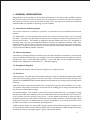
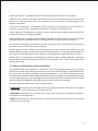
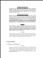
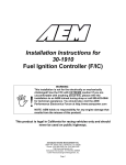
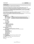
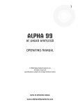
Table of Contents
1. GENERAL INFORMATION . . . . . . . . . . . . . . . . . . . . . . . . . . . . . . . . . . 3
1-1. Introduction and Description . . . . . . . . . . . . . . . . . . . . . . . . . . . . . . . . . . . . . 3
1-2. Owner Assistance . . . . . . . . . . . . . . . . . . . . . . . . . . . . . . . . . . . . . . . . . . . . . 3
1-3. Equipment Supplied . . . . . . . . . . . . . . . . . . . . . . . . . . . . . . . . . . . . . . . . . . . . 3
1-4. Features . . . . . . . . . . . . . . . . . . . . . . . . . . . . . . . . . . . . . . . . . . . . . . . . . . . . . 3
1-5. Safety Considerations, Explicit Definitions . . . . . . . . . . . . . . . . . . . . . . . . . . . 4
2. INSTALLATION . . . . . . . . . . . . . . . . . . . . . . . . . . . . . . . . . . . . . . . . . . . 5
2-1. Unpacking and Initial Inspection . . . . . . . . . . . . . . . . . . . . . . . . . . . . . . . . . . . 5
2-2. Line Voltage Selection . . . . . . . . . . . . . . . . . . . . . . . . . . . . . . . . . . . . . . . . . . 6
2-3. Amplifier Location Selection . . . . . . . . . . . . . . . . . . . . . . . . . . . . . . . . . . . . . 6
2-4. Connections . . . . . . . . . . . . . . . . . . . . . . . . . . . . . . . . . . . . . . . . . . . . . . . . . 6
3. POWER ON, CONTROLS AND INDICATORS . . . . . . . . . . . . . . . . . . . 8
4. OPERATION . . . . . . . . . . . . . . . . . . . . . . . . . . . . . . . . . . . . . . . . . . . . . 10
4-1. Turning ON and OFF . . . . . . . . . . . . . . . . . . . . . . . . . . . . . . . . . . . . . . . . . . 10
4-2. Changing Operate and Standby Modes . . . . . . . . . . . . . . . . . . . . . . . . . . . . 10
4-3. RTTY Mode . . . . . . . . . . . . . . . . . . . . . . . . . . . . . . . . . . . . . . . . . . . . . . . . . 11
4-4. Antenna change . . . . . . . . . . . . . . . . . . . . . . . . . . . . . . . . . . . . . . . . . . . . . . 11
4-5. Tuning . . . . . . . . . . . . . . . . . . . . . . . . . . . . . . . . . . . . . . . . . . . . . . . . . . . . . . 11
5. MAINTENANCE . . . . . . . . . . . . . . . . . . . . . . . . . . . . . . . . . . . . . . . . . . 14
5-1. Cleaning . . . . . . . . . . . . . . . . . . . . . . . . . . . . . . . . . . . . . . . . . . . . . . . . . . . . 14
5-2. Fuse Replacement . . . . . . . . . . . . . . . . . . . . . . . . . . . . . . . . . . . . . . . . . . . . 14
5-3. Tube Replacement . . . . . . . . . . . . . . . . . . . . . . . . . . . . . . . . . . . . . . . . . . . . 15
5-4. Simplified Schematic Diagram . . . . . . . . . . . . . . . . . . . . . . . . . . . . . . . . . . . 15
5-5. Service Functions . . . . . . . . . . . . . . . . . . . . . . . . . . . . . . . . . . . . . . . . . . . . . 16
6. SPECIFICATIONS . . . . . . . . . . . . . . . . . . . . . . . . . . . . . . . . . . . . . . . . . 16
6-1. Parameters . . . . . . . . . . . . . . . . . . . . . . . . . . . . . . . . . . . . . . . . . . . . . . . . . . 16
6-2. Functions . . . . . . . . . . . . . . . . . . . . . . . . . . . . . . . . . . . . . . . . . . . . . . . . . . . 17
6-3. Storage and Shipment . . . . . . . . . . . . . . . . . . . . . . . . . . . . . . . . . . . . . . . . . 18
1
2
1. GENERAL INFORMATION
Congratulations on purchasing one of the finest HF amplifiers in the world today. ACOM is pleased
that you have chosen one of our products, and we will endeavor to provide you with the information
and support you need to enjoy your purchase for many years. We urge you to read all of the following
materials before you embark on operating your new amplifier.
1-1. Introduction and Description
This manual explains the installation, operation, and maintenance of the ACOM1010 HF linear
amplifier.
The ACOM1010 is a self-contained linear amplifier that covers all amateur bands, from 1.8 through
29.7 MHz. It provides over 700 W PEP of output power (or 500 W in continuous-duty operation) with
less than 60 W of drive. The amplifier is designed to tolerate VSWR levels of up to 3:1 throughout its
operating range, and tuning is simplified by ACOM’s exclusive True Resistance Indicator (TRI). Also,
a built-in antenna selector switch with two outputs is included to provide instant choice of antennas.
Importantly, a variety of system parameters are continuously monitored and available to the operator
to assure safe and efficient amplifier operation.
1-2. Owner Assistance
If technical or operating assistance is needed, your local dealer should be contacted first. In the unlikely
event you need further information, you may get in touch with ACOM by facsimile, telephone, email or
standard mail. Fax: + 359 2 920 9656; telephone: + 359 2 920 9655; e-mail: [email protected];
standard mail: ACOM, Bul. N.Mushanov 151, 1330 Sofia, Bulgaria.
1-3. Equipment Supplied
The ACOM1010 amplifier and this manual are shipped in a cardboard carton.
1-4. Features
Easy operation. The plate-load True Resistance Indicator (TRI) is an ACOM innovation that provides
quick and precise tuning, typically in less than 10 seconds. The auto-operate function will return the
amplifier to the OPERATE mode automatically after each protection trip, saving time and avoiding manual
switching.
l
l No tuner needed.
No external antenna tuner is required as long as the antenna VSWR is 3:1 or lower.
The amplifier will perform the functions of an antenna tuner, enabling you to change antennas faster and
use them over wide frequency ranges.
A durable amplifier. This amplifier is both user-friendly and self-monitoring. It is designed to safely
withstand up to 240 W of reflected power, up to 100 milliseconds of drive spikes (RF “tails” after a PTT
or KEY release), and even operator tuning errors. It is also capable of operating at more than half its
designed output power at only 75% of nominal line (mains) voltage. Because it can tolerate deep voltage
drops (down to zero for 10 milliseconds) and 15% line voltage spikes, it is particularly suited for use in
portable environments, such as field days and DXpeditions.
l
LED bar-graph display. The upper LED bar-graph always reads peak forward power (except for the
service functions) while the lower LED bar-graph is for the reflected power. LED warning indicators are
provided for abnormal conditions of grid 1, grid 2, and plate parameters.
l
3
l
Antenna selection. Two antenna outputs are selectable on the front panel of the amplifier.
l Efficient tuning.
Antenna matching can be achieved in less than 10 seconds and at a quarter of nominal
output power, which produces lower risk of interference to other stations and greater safety to the
amplifier components.
Transceiver-independent. The amplifier operates without special signaling from the transceiver; it
needs only “ground on TX” and 60 W RF drive power to operate at full output power.
l
Input matching. Broadband input matching circuitry offers excellent loading characteristics for the
driving transceiver, from 1.8MHz to 30MHz.
l
l Single tube operation.
A single Svetlana 4CX800A (GU74B) high-performance ceramic-metal tetrode
with plate dissipation of 800W (forced air cooling, grid-driven) is used for maximum efficiency.
Permanent monitoring and protection of the plate and grids currents. The Bias Optimizer minimizes
heat dissipated by the tube, assuring tube longevity.
l
High voltage protection. Design of the high-voltage power supply eliminates the danger of turn-on
transients affecting sensitive devices connected to the same line (mains) circuit. Moreover, the amplifier can
be configured to accommodate any of 8 nominal line voltages between 100 and 240 V, 50 or 60 Hz.
l
Band inclusion. The amplifier can be shipped with 10 and 12-meter capability disabled as required by
the Federal Communications Commission (FCC), for United States users. Contact your dealer about
enabling those bands.
l
1-5. Safety Considerations, Explicit Definitions
The ACOM1010 HF Linear Amplifier is a Safety Class I unit. The grounding lead (yellow with 2 green
stripes) of the power cable and the ground stud on the rear panel of the amplifier (marked GND) must
be connected to the station’s grounding system for safe operation. The amplifier is designed to meet
international safety standards and complies with CE safety and electromagnetic compatibility requirements,
as well as FCC regulations. This operating manual contains an assortment of precautions and warnings
that MUST BE FOLLOWED BY THE USER to ensure safe operation of the amplifier.
The safety definitions below apply to this operating manual:
A WARNING is associated with a procedure that, if not properly performed, could result in a fire hazard
or electric shock, with resulting injury or death to the user.
A CAUTION is associated with a procedure that, if not properly performed, could result in damage to
the amplifier or other equipment.
A NOTE is associated with a procedure that, if not properly performed, could result in inconvenience
or physical injury to the user.
4
WARNING HIGH VOLTAGE!
The amplifier works with voltages up to 3000 V dc, which are potentially
LETHAL! You must unplug the amplifier from the line (mains) wall outlet
and WAIT AT LEAST 30 minutes before removing the cover of the amplifier.
Do not touch any part inside while the amplifier is open because dangerous
voltages may remain present.
WARNING HIGH VOLTAGE!
NEVER ALLOW ANYONE, ESPECIALLY CHILDREN, to push anything
into the case holes or to otherwise touch the amplifier or its connecting
cables. There is grave danger of fatal electrical shock. NEVER TOUCH AN
ANTENNA during transmission as this may result in an electric shock or
burns. NEVER EXPOSE the amplifier to rain, snow or any liquids. AVOID
placing the amplifier in excessively dusty environments. DO NOT OBSTRUCT
AIR INTAKE (bottom) or EXHAUST (top cover) areas of the amplifier. Keep
a minimum distance of 50cm (20 inches) clear of the air exhaust opening.
WARNING
Do not undertake or perform any repair or adjustment of your amplifier
yourself, including any attempt to change hardware or firmware. Doing so
creates a potentially fatal shock hazard and may damage the amplifier or
equipment connected to it. ACOM is not responsible for any such personal
injury or equipment damage, whether caused by accident or as a result of
good faith efforts at repair or adjustment.
CAUTION
To avoid damage to the amplifier not covered by ACOM’s warranty, the user is
expected to read and comply with the installation instructions contained in Section 2
of this operating manual. If there are any doubts or questions concerning installation,
operation or safety of the amplifier, the user should contact ACOM.
2. INSTALLATION
2-1. Unpacking and Initial Inspection
NOTE
The first step to installation is to fully read this manual. Then, carefully inspect the
shipping cartons for any physical damage. ACOM ships amplifiers in highly protected
containers, but it cannot assure that mistreatment by shippers will not occur. If there
is any such damage, notify your ACOM dealer immediately. Failure to do so may
invalidate your warranty. In any case, be sure to keep all packing materials for possible
future amplifier shipment.
5
2-2. Line Voltage Selection
CAUTION
To avoid damage to your amplifier and to maintain your warranty coverage, be
certain that the amplifier line (mains) voltage setting corresponds to your nominal
line (mains) voltage.
Normally, the amplifier is delivered with the Voltage Selector set for a nominal line voltage of 240 V. If
your line voltage is not 240 V, you must contact your dealer for instructions on how to change the voltage
selector inside the amplifier. The only exception to this is if the unit has been custom ordered, in which
case the voltage selection will be noted in the Table of Individual Data (Table 2-1, below).
AMP s/n
Tube s/n
Voltage Selector
VAC
Table 2-1. ACOM 1010 Individual Data
2-3. Amplifier Location Selection
Locate the amplifier as close as possible to where it can be used conveniently. Access to the command
knobs and indicator’s area, as well as to the rear panel cabling, will be necessary.
No device that is sensitive to magnetic fields, including dynamic microphones, should be located adjacent
to the right side of the amplifier, where the power transformer is mounted. The amplifier should generally
be placed to the right of your transceiver. No temperature-sensitive devices should be located above
the air exhaust ports. This means the amplifier should not be located under a shelf or other structure
that could impede the free movement of air away from the amplifier.
DO NOT OBSTRUCT AIR INTAKE (bottom) and EXHAUST (top cover) areas of the amplifier. Keep a
minimum clear distance of 50cm (20 inches) above the exhaust opening.
2-4. Connections
Before applying line (mains) voltage to your amplifier, follow the steps listed below in the order they
are presented.
WARNING
Note that your grounding system may have to handle a current of more
than 15 Amperes. This requires an adequately sized and well-maintained
conductor of at least 4 mm2 (AWG 11 or SWG 13). If this is not the case
at your operating location, you should make the necessary changes using a
licensed electrician.
6
Fig. 2-1 Connections
a) Connect the station’s grounding system to the wing-nut ground stud of the amplifier (on the rear
panel, marked GND in Fig. 2-1).
b) Connect a suitable coaxial cable between the transceiver output to the amplifier (rear panel) RF
INPUT SO-239 connector, using PL-259 connector.
CAUTION
The coaxial cable from the amplifier’s output must be capable of handling the
amplifier’s output power safely, particularly on the 10-meter band. It is suggested
that, at a minimum, RG8X (including RG8MINI, RK50-4-11, RK50-4-13) or, even
better, RG213 (including RK50-7-11) coaxial cable be used.
c) Connect a suitable coaxial cable from the antenna to the appropriate amplifier output (on the rear
panel, marked ANT1 or ANT2), using a PL-259 plug.
d) Run a shielded cable from the “ground on transmit” socket or terminal on your transceiver
to the amplifier rear panel KEY-IN socket. The KEY-IN socket uses a standard RCA phono plug
NOTES
Your amplifier will not work if KEY-IN is not connected properly.
Transceiver producers assign different names to their “ground on transmit” output terminals, e.g., TXGND, SEND, T/R-LINE, etc. Some transceivers may require that “ground on transmit” be implemented
by a software command, or by changing the setting of a switch on the rear panel or inside the transceiver.
Check your transceiver’s manual for more information on keying amplifiers.
7
e) Preparation of the wall outlet for the amplifier.
WARNING
If your amplifier is only fitted with one line (mains) fuse, it is suitable for the
European Community ONLY. Your dealer will check that your amplifier is
correctly fused before it is shipped to you, based upon your indicated location.
Customers should check with a qualified electrician if the amplifier is to be
used outside the country in which it was purchased.
Due to different line (mains) standards in different countries, the dealer will provide the correct Safety
Class I plug for your location. The ground lead of the power cable is colored yellow with two green
stripes. If you have any doubts about the correct way to connect these wires, consult your dealer.
WARNING
Before connecting the amplifier to your line (mains) supply, be sure that the
line (mains) supply is correctly wired and is capable of providing the required
current, i.e., up to 5 A from 240 V and 10 A from 120 V. As discussed earlier,
it is very important that the ground lead is adequately sized and properly
connected.
The Power Switch on the front panel must be in the OFF position; only then should you insert the
amplifier’s line (mains) plug into the appropriate wall outlet. At this time the amplifier remains switched
off.
3. POWER ON, CONTROLS AND INDICATORS
CAUTION
Do not turn the amplifier on for at least 2 hours after unpacking it and locating in its
operating location. Pay particular attention whenever the amplifier is moved from
a very cold place to a very warm one because unseen condensation may develop,
and this could result in damage to the high voltage circuits of the amplifier. Under
these circumstances, do not turn the amplifier on for at least 4 hours. A similar effect
could occur following rapid warming of the location, such as winter use of a powerful
electric heater.
CAUTION
To avoid damage that may not be covered by the amplifier warranty, carefully check
that the voltage for which the amplifier is set corresponds to your nominal line (mains)
voltage. See Section 2-2 and Table 2-1.
After following all instructions in Section 2, you may now turn ON the main power switch on the front
panel (Fig. 3-1). The green LED indicator above the switch will illuminate:
8
Fig. 3-1 ACOM1010 Display and Control
Note that the upper LED bar-graph always reads peak forward power, except for the service functions
(Section 5-5). The 800 W-scale resolution is 50 W. Note also that levels below 50 W may be not
detected.
The lower LED bar-graph will indicate reflected power up to 240 W. The scale resolution is 30 W.
The OPER button alternatively switches between the operate and standby modes once the amplifier
has completed its 150-second warm-up period. See Section 4-2.
The RTTY button reduces the output power of the amplifier to 500 W. See Section 4-3.
The button labeled A1-A2 (Section 4-4) changes the antenna output to either antenna 1 or antenna 2,
according to the operator’s choice. It is the operator’s responsibility to connect suitable antennas to
the ANT1 and ANT2 connectors on the rear panel of the amplifier.
The red TX LED illuminates whenever the KEY-IN input is keyed (closed to ground), i.e., when the
transceiver goes into the transmit mode. See Section 2-4(d).
The BAND knob controls the band switch, and LOAD and TUNE are used to adjust their respective
variable air capacitors in the amplifier’s output circuit. The settings of these three controls must be changed
at each band change as well as when an antenna is changed. The three LED indicators located above
the knob LOAD are called the “TRI tuning indicator” and they are used to achieve antenna impedance
matching during a re-tune procedure. Please see Section 4-5 for a discussion of the tuning procedure.
CAUTION
To avoid damage not covered by the amplifier’s warranty, do not turn the BAND
switch while transmitting. Switching while transmitting is called “hot switching” and
it will cause irreparable damage to the band switch.
There are three warning LED indicators and one fault LED indicator located in the bar-graphs area.
The following describe the error conditions and the correct responses (except for the service functions
- Section 5-5):
- G1 – when illuminated, a control-grid overload condition exists; reduce the drive power for safe
operation;
9
- G2 - when illuminated, a screen-grid overload condition exists; reduce the drive power and/or refresh
the tuning (Section 4-5) for safe operation;
- IP - when illuminated, a plate current overload condition exists; reduce the drive power and/or refresh
the tuning (Section 4-5) for safe operation;
- F – when illuminated, the amplifier automatic protection has tripped. If F is accompanied with one of
the G1, G2, or IP condition indicators, the cause of the protection trip will be evident. When F alone is
illuminated, check the keying wiring, Section 2-4(d). See Section 4-6 for details about the auto-protection
system.
4. OPERATION
Operation of the amplifier is simplified through ACOM’s innovative TRI tuning aid, Auto-Operate function,
and automatic protection systems. To make full use of the amplifier’s potential and to configure it to
local conditions, the following information should be read carefully.
4-1. Turning ON and OFF
In order to turn on the amplifier, press the power switch ON at the bottom-right corner of the front
panel. The LED indicator above the switch will glow green and the audible cooling fan will start. Following
a series of automatic self-tests, the OPER LED will begin to flash green and will continue to do so during
the 150-second warm-up period. Throughout this period, the amplifier will remain in the standby mode,
and the transceiver may continue to be used. Also during this period, the A1-A2 button may be pressed
to change antennas, i.e., between the antennas connected to the ANT1 and ANT2 terminals on the rear
panel of the amplifier. Switching between the antennas does not affect the warm-up process.
CAUTION
To avoid damage not covered under warranty, do not change the antenna output
during a transmission, i.e., never press the A1-A2 button when transmitting.
NOTE
When you intend to have a short operating break, it is better to place the amplifier
in the standby mode rather than turning it off. Tube life is shortened by repeatedly
turning it on and off.
After the warm-up period is complete, the OPER LED stops flashing and remains illuminated green.
4-2. Changing Operate and Standby Modes
The OPER button changes between two modes. When the green light above the button is illuminated,
the amplifier will remain ready to operate, even automatically returning from standby after a high-drive
protection trip. That is, after a protection trip, e.g., from an overdrive event, the amplifier will normally
shift to the STBY mode for several seconds, but it will automatically return to the OPER mode after
that. This is the Auto-Operate feature. Alternatively, the OPER button may be depressed manually to
go to and remain in the STBY mode, such as when you leave the station for a while. The green LED
goes off and the Auto-Operate function is suppressed temporarily. Pressing the OPER button again
restores the Auto-Operate feature.
10
4-3. RTTY Mode
Select the RTTY mode to operate continuous-duty modes such as RTTY, SSTV, or other data modes. The
LED indicator above the RTTY button illuminates and the amplifier operating parameters are changed
to reduce tube dissipation. In the RTTY mode, the amplifier output power is reduced to a maximum
of 500 W. There is no need to adjust tuning when changing between RTTY and normal modes.
CAUTION
To avoid damage not covered under warranty, do not change modes during
transmission. That is, do not change to or from RTTY or any other mode when
transmitting.
4-4. Antenna change
By pressing the A1-A2 button, the amplifier output is switched between the two corresponding antenna
outputs, ANT1 and ANT2. The lights above the button indicate the current antenna selection.
CAUTION
To avoid damage (not covered under warranty) do not change the antenna during
transmission.
4-5. Tuning
Tuning is possible only in the OPER mode.
a) Preliminary information.
Tuning the amplifier involves a procedure of matching the impedance of the antenna and transmission
line to the amplifier tube’s characteristic load resistance. This will ensure maximum plate efficiency and
RF gain at nominal output power, with minimal distortion and spurious output. Note that REFLECTED
POWER readings depend on the antenna and transmission line impedances only, and not on amplifier
tuning. If the load impedance is not a nominally resistive 50-Ohms, the REFLECTED POWER reading will
always show a reading, no matter what the tuning settings. Proper tuning is always necessary, however,
and will allow you to operate at a high power level, without distortion or any danger to the amplifier.
Note also that the real OUTPUT POWER presented to the load (the antenna and transmission line)
is equal to the difference between the FORWARD and REFLECTED power readings. For instance,
with a 2.5:1 VSWR, readings of 800 W and 150 W FORWARD POWER and REFLECTED POWER
respectively, the real OUTPUT POWER is 650 W. At very high VSWR levels, such as when no antenna
is connected or a badly mismatched antenna is used, the FORWARD and REFLECTED readings will
be almost equal, while the real OUTPUT POWER (the difference between them) will be nearly zero.
The amplifier can operate safely as long as the REFLECTED POWER is LESS THAN 250 W. Matching
is assured for loads presenting a VSWR of up to 3:1. Nevertheless, for some loads and bands, matching is
possible at even higher VSWR levels, but the drive power must be reduced to prevent the REFLECTED
POWER from exceeding 250W. Failure to comply with these guidelines will cause the protection circuits
to trip. For example, if the antenna VSWR were 5:1, the maximum attainable forward power would be
540 W, 240 W of reflected power and real output to the antenna and transmission line of only 300 W.
In the event your antenna cannot be adjusted to produce a lower VSWR, an external antenna tuner may
be deployed.
11
CAUTION
At elevated VSWR levels, high voltages and high currents are distributed along the
coaxial cable to the antenna, risking internal arcing and heat generation, and likely
damage to the cable and any antenna switches that may be used. It is recommended
that VSWR levels of more than 3:1 not be permitted with coaxial cable above
14 MHz.
It is advisable to adjust amplifier tuning when antennas have been changed, snow has fallen, new objects
are in the near field of the antenna, etc. Such changes may affect antenna impedance.
NOTE
If you use more than one antenna on a band, the proper antenna must be selected
prior to performing the tuning procedure outlined below.
CAUTION
To avoid damage not covered under warranty, do not switch the BAND switch knob
while transmitting. As discussed above, hot switching will damage the amplifier’s
band switch!
CAUTION
Also, never apply drive longer than one minute continuously without pausing for at
least one minute to allow the tube to cool.
It is recommended that for initial tuning a frequency in the middle of the band be used. First, with no
transceiver power applied, select the band. Then use Table 4-1 to achieve an approximate preset for
both TUNE and LOAD capacitor knob settings:
Band MHz
LOAD Knob Dial
TUNE Knob Dial
1.800 - 2.000
47 - 71
54 - 32
3.500 - 4.000
34 - 56
51 - 33
7.000 - 7.300
32 - 39
36 - 30
10.100 - 10.150
62 - 63
50 - 48
14.000 - 14.350
37 - 41
38 - 31
18.068 - 18.168
41 - 43
50 - 48
21.000 - 21.450
59 - 62
16 - 10
24.890 - 24.990
50 - 52
49 - 46
28.000 - 29.700
63 - 69
23 - 10
Table 4-1. Approximate tuning preset
b) Tuning Procedure.
(1) Once the antenna and band have been selected (and the TUNE and LOAD adjustments have
been initially set as indicated in Table 4-1), apply between 10 and 20 W of continuous (key down CW)
signal.
(2) Look at the upper LED bar-graph (FORWARD POWER) and adjust the TUNE (right hand) capacitor
for maximum indication.
12
(3) Watch the TRI indicator above the LOAD (left hand) capacitor and turn the LOAD capacitor in the
indicated direction to center the green LED indicator light.
(4) Increase the drive power to get the desired nominal output; then repeat steps (2) and (3), always
peaking output with the TUNE adjustment.
NOTE
No light on the TRI indicator means that the tuning is too far off. To correct this,
turn the LOAD and TUNE knobs around the table-suggested positions until the TRI
indicator illuminates.
no light:
use TUNE knob
for max. Power
to get any marker
tuning is far left:
turn LOAD knob
to the right to get
the inside markers
tuning is far right:
turn LOAD knob
to the left to get
inside markers
marker inside:
turn LOAD knob
slightly left
to center it
LOAD is tuned:
turn TUNE knob
to peak Forward
Power
Fig. 4-1. Using TRI tuning aid
The TRI indicator will not illuminate until at least 20 W of forward power (output) is achieved. In the event
successful matching cannot be accomplished, check the BAND switch position and antenna selection.
Then check the antenna VSWR at the same drive frequency.
d) Tuning hint. A benefit of TRI is that the knob positions are virtually independent. The plate-load
resistance decreases to the right and increases to the left of the TRI center. A centered tuning indication
corresponds to the proper LOAD capacitor tuning, which presents an optimum load resistance to the
tube.
If the LOAD knob is turned to the left with a centered TRI, there will be more gain, but less linearity.
When available drive power is insufficient or when less output but better efficiency are needed, e.g.,
for RTTY and SSTV, this may be desirable. Tuning to the right of the center would lead to the opposite
result, i.e., less gain and more power attainable. Of course, this requires more drive power, more plate
current, and more plate heat, which shortens tube’s-expected life. Off -center tuning may also be used to
compensate for line (mains) voltage variations in order to maintain tube efficiency. In that case, tune to
the left when line (mains) voltage is high, or tune to the right if it is low. However, where there is more
than a 10% difference from the nominal line (mains) voltage, the voltage selector inside the amplifier
should be changed. See Section 2-2 (Line Voltage Selection).
4-6 The Auto-Protection System
When any abnormal amplifier condition is detected by the auto-protection microprocessor, the risk will
be evaluated automatically and either of two levels of protection will be applied:
a) The first degree of protection consists of an illuminated LED warning. These include the yellow
LED warnings discussed earlier, i.e., “G1” (grid 1), “G2,” (grid 2), and “IP” (plate). Operation may be
continued but the amplifier is likely to proceed to the second degree of protection, the trip.
b) The second degree of protection is a trip to the standby mode. The red “F” (fault) LED illuminates
and the amplifier automatically goes to the standby mode for several seconds. Also, the green OPER
LED goes off. The amplifier will indicate the reason for the protection trip:
13
- if one of the yellow (G1, G2, IP) warning LEDs is illuminated along with the “F” LED, a current limit
has been exceeded; drive power must be reduced or retuning is necessary;
- if the last red LED of the reflected-power bar-graph is illuminated together with the “F” LED, the
reflected-power limit has been exceeded; the drive must be reduced or the antenna VSWR must be
improved.
- if all three LEDs of the TRI are flashing simultaneously together with the “F” LED, the tuning is not
adjusted correctly; most likely the antenna impedance has changed and retuning is required.
Fault information normally remains on the display for several seconds while the amplifier is in the standby
mode. The auto-operate function will attempt to return the amplifier to the operate mode automatically.
If the protection trips repeatedly, the user must attend to the cause of the trip, which is typically too
much drive or antenna mismatch.
CAUTION
If all LEDs in the bar-graph area are flashing simultaneously, you must immediately
switch off the amplifier to avoid damage.
5. MAINTENANCE
If no indicator glows upon switching the amplifier on, the main fuse(s) may have blown. See Section
5-2.
5-1. Cleaning
WARNING
Do not use solvents for cleaning as they may be dangerous to you and damage
amplifier surfaces and plastic components.
Do not open the amplifier. Cleaning the amplifier outer surface may be safely accomplished by using a
piece of soft cotton cloth lightly moistened with clean water.
5-2. Fuse Replacement
WARNING
If your amplifier is only fitted with one line (mains) fuse, it is suitable for the
European Community ONLY. Your dealer will check that your amplifier is
correctly fused before it is shipped to you, based upon your indicated location.
Customers should check with a qualified electrician if the amplifier is to be
used outside the country in which it was purchased.
CAUTION
For 120 V ac operation, the fuses should be rated at 10 A; for 240 V ac operation,
the fuses should be rated at 6.3 A. If it is necessary to replace the line (mains) fuses,
use only those that are permitted under local safety codes.
14
The two primary line (mains) fuses in the amplifier are located on the rear panel (Fig. 2-1). They are of
the fast (quick blow) type, European size 5 x 20 mm. Use 10 A for 100-120 V ac operation; 6.3 A for
200-240 V ac operation. Suitable types are:
For 120 V: 10 A 250 V 5 x 20 mm fast (quick blow), LITTELFUSE 0217010; Wickmann 1942100000
For 240 V: 6.3 A 250 V 5 x 20 mm fast (quick blow), LITTELFUSE 021706.3; Wickmann 1931630000
Besides the primary fuses, there are also fuses located on the HV PCB and on the MAINS PCB (inside
the amplifier). They are European size 5 x 20 mm, 0.8 A, 2 A and 5 A, time lag (slow-blow) type.
Suitable types are:
HV PCB: 2 A 250 V SLOW BLOW (Time Lag) 5 x 20 mm; LITTELFUSE 0218002; Wickmann
1951200000
MAINS PCB: 5 A 250 V SLOW BLOW (Time Lag) 5 x 20 mm; LITTELFUSE 0218005; Wickmann
1951500000
MAINS PCB: 0.8 A 250 V SLOW BLOW (Time Lag) 5 x 20 mm; BUSSMANN type S504-800mA
These latter fuses must not be replaced by the user. Replacing these internal fuses is potentially dangerous
and must be done only by a trained service technician. Contact your ACOM dealer for assistance.
5-3. Tube Replacement
A single Svetlana 4CX800A (GU74B) high-performance ceramic-metal tetrode is used in the amplifier.
Replacement is a complex and potentially dangerous operation that involves adjustment of the plate idling
current. This should not be attempted by the user. Contact your ACOM dealer.
5-4. Simplified Schematic Diagram
See Fig. 5-1 ACOM1010 Simplified* Schematic Diagram. The 4CX800A (GU74B) Svetlana high
performance ceramic-metal tetrode (V1) with plate dissipation of 800 W is grid-driven. The input
signal from the RF INPUT jack is passed through a broadband input matching circuit, which consists of
components on the INPUT PCB and includes the drive-power swamping resistor Rsw. This circuit tunes
out the input capacitance of the tube. The swamping resistor Rsw is a termination load for the matching
circuit and can dissipate up to 80 W of RF drive power. It also eliminates any tendency toward oscillation
by the tube, ensuring excellent RF stability of the amplifier.
The cathode resistor Rc creates DC and RF negative feedback, thus stabilizing gain and equalizing
frequency response. The combination Lp1-Rp1 in the plate circuit is a VHF/UHF parasitic suppressor.
DC plate voltage is fed through chokes RFC1-RFC2 and the capacitor Cb3 blocks it from the output.
The output tank, comprised of LP1, LP2, LL, CP1-CP3, and CL1-CL4 , forms a classic Pi-L network
and suppress harmonic frequency emissions. This circuit is switched and tuned by S1A-S1C and the air
variable capacitors CP1, 2 and CL1, 2. The output signal is fed through the antenna relays K1 and K2 in
the WATTMETER PCB. The WATTMETER PCB also includes a high-pass filter for frequencies below
100 kHz, and it prevents the plate supply from reaching the antenna.
The plate RF voltage is monitored through the capacitor Ca and together with the RF WATTMETER is
the main source of information for the control circuit of the amplifier in evaluating tuning quality. The
control circuit is based on the ATMEGA-8L micro-controller from Atmel. All voltages are delivered from
the line (MAINS) and HV PCBs. The currents of the control grid, screen grid, and the plate, as well as
the reflected power and tuning quality, etc., are continuously monitored by the micro-controller. Many
15
software-derived protections are based on this information.
* Detailed electrical schematic diagrams are available from ACOM or from your dealer on request.
5-5. Service Functions
By pressing the OPER and RTTY buttons simultaneously, the upper LED bar-graph is switched to the
service mode, which is indicated by both red bar-graph lights and the yellow G1 light illuminating. Pressing
the OPER and RTTY buttons together again will select additional service measurement functions.
Pressing them a final time will return the amplifier to the normal operating mode. These steps are
detailed below:
a) Press the OPER and RTTY buttons together. The two red lights on the right side of the upper
bar-graph will illuminate to confirm that the amplifier is in the service mode. The yellow G1 light will
also illuminate. The upper bar-graph should show a grid 1 current reading no higher than 5 mA (5 LEDs
illuminated).
b) Pressing the OPER and RTTY buttons once again will now illuminate the yellow G2 light. This
provides an approximate reading of grid 2 voltage. The upper bar graph should show a voltage reading
within the range of either 270-300 Volts (9-10 LEDs illuminated) for RTTY or 210-330 Volts (7 to 11
LEDs illuminated) for SSB and CW.
c) Pressing the OPER and RTTY buttons yet again will illuminate the yellow IP light. This provides an
approximate reading of combined plate current and grid 2 current. The reading should be no higher
than 500 mA (10 LEDs illuminated) for RTTY or 600 mA (12 LEDs illuminated) for SSB and CW.
d) Pressing the OPER and RTTY buttons a final time will restore the upper bar-graph to its normal
function of indicating peak forward power.
NOTE
The auto-protection system will continue to operate in the service mode.
6. SPECIFICATIONS
6-1. Parameters
a) Frequency Coverage: All amateur bands in the 1.8-29.7MHz frequency range; extensions and/or
changes on request.
b) Power Output: 700 W PEP or 500 W continuous carrier.
c) Intermodulation Distortion: Better than 35 dB below rated output.
d) Hum and noise: Better than 40 dB below rated output.
e) Harmonic Output Suppression: Better than 50 dB below rated output.
f) Input and Output Impedance:
- Nominal value: 50 Ohm unbalanced, UHF (SO-239) type connectors;
- Input circuit: broadband, VSWR less than 1.3:1, 1.8-30 MHz continuously (no tuning, no switching);
16
- Bypass path: VSWR less than 1.1:1, 1.8-30 MHz continuously, 200 W maximum;
- Output (antenna) impedance matching capability: VSWR up to 3:1 or higher.
g) RF Gain: 11dB typically, frequency response less than 1dB (50 to 70 W drive power for rated
output).
h) Primary Power: 85-132 V/170-264 V ac (100, 110, 120, 200, 210, 220, 230 & 240 V nominal taps),
+10% -15% tol.), 50-60 Hz, single phase, 1200 VA.
i) Complies with CE safety and electromagnetic compatibility requirements as well as FCC-regulations
(10 & 12 m band locks provided).
j) Size & Weight (operating): WxDxH: 402x315x166mm, 18kg (15.83x12.4x6.5 inches, 39.7Lbs).
k) Operating environments:
- Temperature range: 0 to +50 degrees Celsius;
- Humidity: up to 95% @ +35 degrees Celsius.
- Height: up to 3000 m above sea level without output deterioration.
6-2. Functions
a) Antenna Impedance Matching Process: aided by a plate-load True Resistance Indicator (TRI).
b) Two antenna outputs selectable by a button on the front panel.
c) Protections:
- Cover interlock for operator’s safety;
- Inrush power-on current limited to the nominal consumption;
- Control grid, screen grid, and plate currents;
- T/R sequencing;
- Antenna relay contacts, including RF power induced in antenna from another nearby transmitter;
- Antenna matching quality;
- Reflected power.
d) LED bar-graphs for forward peak power and reflected power.
e) Service visualization of grid 1 DC current, grid 2 DC voltage, and plate DC current.
f) Tube: a single Svetlana 4CX800A (GU74B) high-performance ceramic-metal tetrode with plate
dissipation of 800 W, grid driven, forced air-cooling.
17
6-3. Storage and Shipment
CAUTION
Should it be necessary to ship the amplifier, use the original packing as described
below.
Switch off the amplifier, pull the line (mains) plug out of the outlet, disconnect all cables from the rear
panel of the amplifier (remove the ground connection the last), and then pack the amplifier in its original
carton.
a) Acceptable storage environment: The amplifier may be kept packed in a dry, ventilated and unheated
location (with no chemically active substances such as acids or alkalis) within the following environment
ranges:
- Temperature range: -40 to +70 degrees Celsius
- Humidity: up to 75% @ +35 degrees Celsius.
b) Shipping Size and Weight: WxDxH: 535x445x270mm, 21kg (21x17.5x10.6 inches, 46.3Lbs).
c) All types of transportation may be used, including storage in an aircraft baggage compartment at up
to 12000 meters above sea level.
18
0.2pF
Ca
Lp1
Rp1
120/3W
Input Relay
TQ2-12V
Rsw
50/100W
2,
4, 6
3
7
Rc.1
22/2W
INPUT
PCB
1
0
Cb1.2
2.2n/6kV
RFC2
22uH
Rc.2
22/2W
2x10n/500V
VSsg
V230LA20A
G2
8
2
7
12
24/28
6
1.8MHz
1
1
18/21
5
3.5MHz
12
2
3
4
14MHz
10MHz
TUNE
Ch2
9
11
Cb2
2.2n/6kV
Ch1
3.5
BAND
Cb1.1
2.2n/6kV
Csg
12x820pF
1kV
*PART OF
SOCKET
LP1
47uH
1.8-10MHz
1.8
1
G1
R50
K1
RX/TX
A1
K2
A1/A2
A1
SO239
L-COIL
PI-COILS
CP1
5/35pF
RFC1
160uH
PLATE
CHOKE
A
IN
GND
Cb3.2
5
RF
INPUT
SO239
S1C
L-section
1.8MHz pos.
S1B
PI-section
1.8MHz pos.
RX
V1
4CX800A
(GU74B)
GND RX
S1A
PLATE-section
1.8MHz pos.
2x2.2n/6kV
Cb3.1
CP2
10/175pF
3
CP3
100pF
3.5kV
4kVA
4
1
0
5
3.5
7
1
0
3
4
5
2
6
7
1
7
8
12
9
A2
SO239
A2
GNE
WATTMETER
12
84
/ /
22
18
1
4
6
JP1
8
1
1
CL1
12/340pF
1
0
9
CL4.1-CL4.4
4x130pF/2kV/1.5kVA
CL2
15/450pF
LOAD
LID
CROWBAR
TX
LL
10.4uH
1.8-30MHz
1.8
12
14 8 4
/ /
22
18
7;10
1
1
7MHz
LP2
1.9uH
18-30MHz
CL3
130pF/2kV/2.5kVA
U
JP1
TUBE DECK
RF SECTION
+HV
BLOWER
12VDC
TRI
M1
JP2
G1/G2
TUBE DECK
+HV
J1 J2
Heater
T1
MAINS VOLTAGE SELECTOR
A1
120,240
A2
MA
110,220,230
120
100,200,210
T4
A4
210,220
110
A7
100
T2
T3
A5 230,
240
A6
MB
A3
A8
100,110,120
T5
T6
T7
T8
0V
10V
10V
T15
1660V
LED
HV
PCB
T18
100V
0V
10V
10V
T13
270V
T14
100V
200
HVRET GND
black
M1
SW
POWER ON
250V/10A
b
l
a
c
k
+380V
380RET
JP3
KBD
JP1
MAINS PCB
T9
T10
b
r
o
w
n
JP4
TRI
TV1
+BLOWER
brown
JP2
TUBE DECK & WATTMETER
13.2V
CONTROL PCB
92V
1
G1
M2
K
6
FA
JP1
CONTROL PCB
FB
6.3A @ 200-240V
10A @ 100-120V
1.8MHz position
S1B
front view
S1A
rear view
MAINS PCB
7
6
RFC
10uH
5
o
RFC3
22uH
o
KEY-IN
(Rear Panel)
Cb4
10n/500V
6
8
4
S1C
front view
6
7
5
8
7
5
8
4
9
4
9
4
9
3
10
3
10
3
10
2
black
K
4CX800A
(GU74B)
Bottom View
JP3
HV PCB
b
r
o
w
n
G2
5
T12
C1
C2
2.2n/3kV
b 2.2n/3kV
l
a
c
R1
k
1M/1W
H 3
7 H
KBD BUTTONS & LEDS
T11
COVER
INTERLOCK
250V/10A
2
K
11
2
11
2
11
brown
1
AC LINE CORD
100-240VAC
8 taps
12
1
12
1
12
Fig. 5-1 ACOM1010 Simplified Schematic Diagram