1
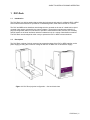
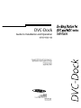
GUIDE TO INSTALLATION AND OPERATION
Safety Compliance Information
Safety Compliance
This equipment complies with:
-
CSA C22.2 No. 60950-1-03 / Safety of Information Technology Equipment, Including Electrical Business
Equipment.
st
UL 60950-1 (1 Edition) / Safety of Information Technology Equipment, Including Electrical Business Equipment.
st
IEC 60950-1 (1 Edition) / Safety of Information Technology Equipment, Including Electrical Business Equipment.
CAUTION
These servicing instructions are for use by qualified service personnel only. To reduce the risk of electric shock, do
not perform any servicing other than that contained in the operating instructions unless you are qualified to do so.
Refer all servicing to qualified service personnel. Servicing should be done in a static-free environment.
Electromagnetic Compatibility
-
This equipment has been tested for verification of compliance with FCC Part 15, Subpart B, class A requirements
for Digital Devices.
This equipment complies with the requirements of:
EN 55022 Class A, Electromagnetic Emissions,
EN 61000-3-2 & -3-3, Disturbance in Supply Systems
EN 61000-4-2, -3, -4, -5, -6, -8 & -11 Electromagnetic Immunity
How to contact us:
For technical assistance, please contact the Miranda Technical support centre nearest you:
Americas
Telephone:
+1-800-224-7882
e-mail:
[email protected]
Asia
Telephone:
+81-3-5730-2987
e-mail:
[email protected]
Visit our web site at www.miranda.com
DVC-Dock
Europe, Middle East,
Africa, UK
Telephone:
+44 (0) 1491 820222
e-mail:
[email protected]
France (only)
Telephone:
+33 (0) 1 55 86 87 88
e-mail:
[email protected]
GUIDE TO INSTALLATION AND OPERATION
1 DVC-Dock
1.1
Introduction
The DVC-Dock is a docking station that provides physical support and power for a Miranda DVC or MDCseries interface that needs to be operated in a freestanding mode, rather than mounted on a camera.
The DVC and MDC-series interfaces were designed to be mounted on the rear of a hand-held or tripodmounted video camera, powered by the camera’s battery. These design requirements resulted in a
physical configuration that is not convenient to operate in a stand-alone mode. However, the versatility
and full feature set of these interfaces make them attractive tools in a variety of stand-alone scenarios.
The DVC-Dock was developed to make it easy to operate the DVC or MDC in those situations.
1.2
Description
The DVC-Dock consists of a body contoured to support the shape of the DVC or MDC interface, and a
power supply providing the correct DC voltage for the DVC or MDC from a 120-240VAC supply.
Figure 1.1 DVC-Dock physical configuration – front and back views
DVC-Dock | 1
GUIDE TO INSTALLATION AND OPERATION
2 Operation
To install the DVC or MDC in the DVC-Dock,
•
Place the DVC-Dock on a flat surface
•
Position the DVC or MDC with the power
connector at the bottom and facing out
•
Slide the DVC or MDC into the slots on the
side of the DVC-Dock
•
Plug the power connector into the DVC or
MDC’s receptacle
•
Connect an AC power cord to the receptacle
on top of the DVC-Dock
•
Power will be applied to the DVC or MDC
when the AC cord is plugged into a 120VAC
supply.
Note that the DVC or MDC is held in place by its
weight only, as it is not physically connected to the
DVC-Dock except by the power cord.
See the DVC or MDC User’s Manual for all
information regarding the connection and operation
of the DVC or MDC.
Figure 2.2
3 Specifications
POWER IN
120 - 240VAC nominal
POWER OUT
+12VDC nominal +/- 5%
POWER CONNECTOR
XLR-4
2 | DVC-Dock
Installing the DVC or MDC-series
interface in the DVC-Dock