1
Motion Controlled RC Car
Kon-41.3131 Mechatronics Exercises
Presented:
April 18, 2012
By:
Henri Helkiö
Jacob Sindberg
Fredrik Sjöblom
Tatu Pollari:
1
Table of contents
Description:
Page:
Project goals
Procedure
Phase 1: Balance board and computer
Phase 2: Arduino and transmitter
Final Results
Further development
User’s Manual
Attachments
3
3
4
4
7
7
8
9
List of components
Arduino code
Python code
Modified WiiBoard library
9
9
17
19
2
Project Goals:
The goal of our project was to be able to control an RC car with a wii balance board. We wanted the car
to go forward when user was leaning forward and also we wanted the car to go backward when the user
was leaning backward. And the same procedure with steering right and left. We wanted to have a
proportional steering in all four directions.
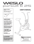
Procedure:
None of us have had much experience with these kinds of projects; therefore we started the project by
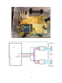
gathering information and figuring out what needed to be done. We found out that we needed a
computer between the balance board and the RC transmitter. The balance board cannot connect to
Arduino directly even if the Arduino would have had a Bluetooth module because neither one of them
can operate as a host, they are both additional devices. Bluetooth connection always needs a host so we
needed a computer for that. An Arduino microcontroller was needed to be able to control the
transmitter and some programming was also needed. We decided to split this project into two pieces.
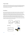
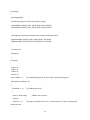
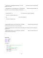
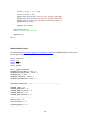
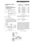
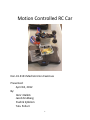
The first task was to have a connection between the balance board and the computer and to be able to
read signals received from balance board. The other task was to send those signals through the Arduino
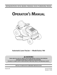
to the RC car. A sketch of our project can be seen in figure 1.
Figure 1
3
Phase 1: Balance board and computer
We started this phase by gathering more information about how to able to read those signals, sent by
balance board, with the computer. We were able to find some projects that had done this by using
program called “GlovePie”. To be able to use GlovePie we also needed a program called “BlueSoleil”
which is a program that creates a Bluetooth connection to the computer with the device desired.
BlueSoleil was needed because the GlovePie was not able to find balance board with the standard
Bluetooth connection created by computer. With these two programs we were able to read the x and y
values from balance board, but we were not able to send those values to Arduino. For the sending we
would have needed a program called “Processing” and for that program a library called “oscP5” which
stands for “open sound control”. However, it wasn’t that easy to use this program and we realized that
this whole project was getting too complex and heavy so we decided to use our plan B.
We decided to write our own code for reading the signals from balance board. We decided to write this
program with Python because we found a good library for Python that was used in a similar project. We
also found some examples of similar projects that were made with Python. The library was called
“wiiboard simple” and it used another library called “pygame”. The advantages of using these libraries
were that they made the Bluetooth connection and also read the data from balance board. So all we
needed to do was to write the main program which used these libraries and transformed the data so
that it could be sent to Arduino. These programs were written by studying how those two libraries
function. We also added a xy-coordinate system to computer so that we were able to see graphically
what values the balance board was sending.
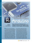
Phase 2: Arduino and transmitter
The idea of the project was to use the Arduino controller to take inputs from the PC, and then control
the throttle and steering channels on the radio transmitter. The Arduino controller used was an Arduino
Uno, connected with a USB cable to the computer. For programming, we used the Arduino software for
the PC.
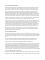
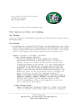
The first step was to disassemble the transmitter and take out the circuit boards, battery box and
antenna. The steering and throttle inputs were controlled with 2 analog potentiometers in the
transmitter casing, connected to a steering wheel and a trigger for throttle/reverse.
Our first idea was to simply measure the voltage difference over the potentiometers in neutral and both
end positions. Next, was to recreate the same voltage range with the Arduino using the Arduino’s pulse
width modulation-based AnalogWrite function. However, this did not work. By measuring the voltage
difference over the potentiometer with an oscilloscope we found out that the voltage in the transmitter
circuit was not constant, but instead a 50 Hz pulse signal. Turning the potentiometers then caused a
change in pulse height, so we could conclude that the transmitter was using pulse amplitude modulation.
This could not be handled with the Arduino alone.
We found out that the easiest way to get it working was to simulate the actual resistance of the analog
potentiometers. This could be done using digital potentiometers, which behaves the same as an analog
4
potentiometer, but is controlled digitally instead of manually. On the Arduino website we found the
Mcp4261 code library, which can be used to control digital potentiometers using SPI (Serial Peripheral
Interface). However, it was not compatible with the Arduino’s standard “SPI.h” library. After a bit more
searching, we found an updated library called “McpDigitalPot.h” (available at
https://github.com/teabot/McpDigitalPot) which is compatible with the standard SPI library, so we
decided to use this library. For digital pots we chose two MCP4161 10kohm single-channel digital pots,
which were easily available and seemed to suit our needs.
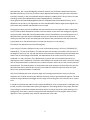
The digital pots were put on a breadboard and connected by wires to the Arduino and the transmitter
circuit. The wires were soldered to the holes in the transmitter circuit where the analog pots originally
were connected. Unlike dual-channel potentiometers, which have different input and output pins, the
MCP4161 have input and output multiplexed onto one pin. We found out that since we will not be
reading any data from the pot, we could ignore the output of the potentiometer and only connect the
input/output pin on the potentiometer to its input (an output pin on the Arduino).
The code for the Arduino works in the following way:
A text string of 4 numbers (weight on every corner of the balance board, in the form “50/20/20/10/”),
separated by '/' is sent to the Arduino. The Arduino saves each number as a variable. Then the sums of
the weight on the front, rear, left and right halves of the board are calculated.Using the calculated sums,
and the sum of all the weight of the board, the displacement of the center of mass on the board is
calculated in x- and y-directions. If the displacement is greater than a certain dead zone value, the
displacement value is mapped to a resistance value between the neutral value and the end value. Finally,
each of the potentiometers is selected in turn, and the resistance value is sent to the currently selected
potentiometer. The potentiometers are connected to the same output pin on the Arduino, but only the
potentiometer with its selection pin currently set to LOW will receive the input data. After the input
data is sent, the potentiometer is unselected.
At first we tried using the same resistance range as the analog potentiometers, but the car did not
respond to this. Instead, we had to test different resistance values to get the desired response. The used
resistance range ended up much bigger than the range of the analog pots. The reason for this is unclear
to us.
It should be noted that the Arduino code is long and ineffective, since our experience in coding was very
limited, and parts of the code where quickly put together in the ending phases of the project, when we
were making the connection between the Arduino and PC. As we got the whole system working in the
ending phase, there was no time for tuning and further development of the program and the control
algorithm. There is probably much room for improvements in the code.
5
6
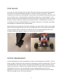
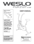
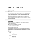
Final results:
In the end, our results matched up with our goals! After some long hours of programming and getting
the arduino microcontroller hooked up with the car controller correctly, the car works. Once all
components are turned on the code updated, if a person were to stand perfectly balanced on the board,
the car would not move. Leaning forward on the board then allows the car to move forward. In this
direction, speed can even be controlled on how far the person leans. When going in reverse, it is a little
bit trickier, as there is mostly one speed, but the function still works. Finally, the person can steer the
car properly, left or right, simply be shifting his or her weight on the board. In conclusion, we created a
functioning RC car controlled by using a balance board.
We tested the system outside and it worked fine, although it was quite hard to be able to drive straight.
There are also some problems that occur every once and a while: there is some contact issues with the
wiring, the program freezes sometimes and sometimes the car starts going backwards when user is
leaning forward and the opposite. However the steering works fine all the time.
Further development:
In further developing our motion controlled RC car, there are several things that can be done. The first
thing to consider is taking the current bread board, and making a printed circuit board (PCB). As of now,
the bread board has two chips and wires running everywhere between the original controller and the
arduino microcontroller. Therefore, two small PCB’s could be constructed for the chips with the proper
configuration for the wires. Time was tight when it came to getting ready to present for the
Mechatronics Circus, so this task never occurred. However, it would not take too much time and the
PCB seminar taught earlier in the course would help.
7
A second task that could be done is to refine our computer code. Both the python and arduino code
potentially have minor flaws in them. This is because every once in a while the program will freeze up,
particularly when the car would go in reverse suddenly or for an extended period of time. None of the
four group members have had substantial work with programming, so consulting a computer engineer
or electrical engineer with more experience would help our situation. Also, we could add more code to
the programs in order to make the driving of the car more precise. This can always be improved, since it
is our first time conducting such a project. Steering could be made sharper and acceleration faster or
slower depending on one’s weight on the balance board. None the less, the car still operates properly
and the overall programming is successful.
To make our project even more sophisticated, we could remove the computer all together. Not having
the PC act as a host between the balance board and controller would require much more time and could
maybe be carried on in a future project. One way to directly improve our car is to use an expansion
shield with the arduino microcontroller. This little component could replace the computer itself and
connect the two main components. It would require much more coding with the device in order to
make it compatible with the existing code, and the existing code would most likely need to be
manipulated as well. Another solution would be to start all over with a bigger microcontroller. Our
current microcontroller is quite small and general, as we did not need the more expensive one using a
PC. If the controller were bigger, Bluetooth accessible, and could act as a host, the PC host could be
replaced and the project would be improved.
User's manual:
1. Connect arduino to computer with USB cord
2. Turn power on in all devices
3. Start eclipse
4. Run the main program
5. Follow instructions on screen
Note: If the program fails after the board has been connected to the PC, you will need to restart the PC.
8
Attachments:
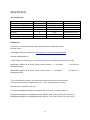
List of components
Name
LRP S10 Twister Buggy
Snakebyte balance board
Arduino UNO Atmega 328 SMD
PC
MCP4161
Logic NX85E Vector
Orion sport power 3300mAh
Units
Price (€)
1
1
1
1
2
1
1
135,00
29,90
23,90
20,00
36,40
26,90
Description
RC Car
Balance board
Microcontroller
Bluetooth host
Digital potentiometer
Battery charger
Extra battery
Arduino code
//SPI library for communicating with digital potentiometers through SPI protocol
#include <SPI.h>
// McpDigitalPot library available from https://github.com/dreamcat4/McpDigitalPot
#include <McpDigitalPot.h>
// Then choose any other free pin as the Slave Select (pin 10 if the default but doesnt have to be)
#define MCP_DIGITAL_POT1_SLAVE_SELECT_PIN 10 //arduino <-> Chip Select
McpDigitalPot DIP)
#define MCP_DIGITAL_POT2_SLAVE_SELECT_PIN 9 //arduino <-> Chip Select
McpDigitalPot DIP)
-> CS (Pin 01 on
-> CS (Pin 01 on
// Its recommended to measure the rated end-end resistance (terminal A to terminal B)
// Because this can vary by a large margin, up to -+ 20%. And temperature variations.
float rAB_ohms = 9700.00; // 10k Ohm
// Instantiate McpDigitalPot object, with default rW (=117.5 ohm, its typical resistance)
McpDigitalPot digitalPot1 = McpDigitalPot( MCP_DIGITAL_POT1_SLAVE_SELECT_PIN, rAB_ohms );
McpDigitalPot digitalPot2 = McpDigitalPot( MCP_DIGITAL_POT2_SLAVE_SELECT_PIN, rAB_ohms );
9
// Instantiate McpDigitalPot object, after measuring the real rW wiper resistance
// McpDigitalPot digitalPot = McpDigitalPot( MCP_DIGITAL_POT_SLAVE_SELECT_PIN, rAB_ohms,
rW_ohms );
//Declaring x- and y-displacement of operator's center of mass on the board, measured in % from center
of board
double xDisplacement = 0;
double yDisplacement = 0;
//Declaring helper variables
double frontWeight; //Total weight on the front
double rearWeight;
//Total weight on the rear
double leftWeight;
//Total weight on the left
double rightWeight;
//Total weight on the right
double totalWeight;
//Total weight
double FL = 0;
//Weight on the front left
double FR = 0;
//Weight on the front right
double RL = 0;
//Weight on the rear left
double RR = 0;
//Weight on the rear right
double throttle;
//Throttle value
double steering;
//Steering value
double throttleResistance;
//Resistance value for the throttle potentiometer
double steeringResistance;
//Resistance value for the steering potentiometer
char FL_input[4];
char FR_input[4];
char RL_input[4];
char RR_input[4];
//A char table to read front left input as a text string
//A char table to read front right input as a text string
//A char table to read rear left input as a text string
//A char table to read rear right input as a text string
char inChar = -1;
//A char where each input char will be read
byte index1 = 0; //Index for going through the FL input string
byte index2 = 0; //Index for going through the FR input string
byte index3 = 0; //Index for going through the RL input string
byte index4 = 0; //Index for going through the RR input string
//Neutral resistance values for throttle and steering, these will be applied when the user input is zero (or
within the deadzone)
double neutralThrottleResistance = 3500;
double neutralSteeringResistance = 3300;
10
void setup()
{
Serial.begin(9600);
//Declaring output pins for the slave selection signal
pinMode(MCP_DIGITAL_POT1_SLAVE_SELECT_PIN, OUTPUT);
pinMode(MCP_DIGITAL_POT2_SLAVE_SELECT_PIN, OUTPUT);
//Setting both selection pins HIGH (so they are both unselected at first)
digitalWrite(MCP_DIGITAL_POT1_SLAVE_SELECT_PIN, HIGH);
digitalWrite(MCP_DIGITAL_POT2_SLAVE_SELECT_PIN, HIGH);
// initialize SPI:
SPI.begin();
}
void loop()
{
index1 = 0;
index2 = 0;
index3 = 0;
index4 = 0;
byte readChar = 1;
//A variable keeping track of which input is currently being read
while (Serial.available() > 0)
{
if (readChar == 1)
//If reading input 1 (FL)
{
inChar = Serial.read();
delay(1);
if (inChar != '/')
index every time
{
//Read 1 char to inChar
//As long as the input text is not '/', save the input to FL_input, increasing the
11
FL_input[index1] = inChar;
index1++;
}
else //If input is '/', that is the end of the current input, put end of string to FL_input and start
reading the next input by increasing readChar by 1
{
FL_input[index1] = '\0';
readChar++;
}
}
if (readChar == 2)
{
inChar = Serial.read();
delay(1);
if (inChar != '/')
{
FR_input[index2] = inChar;
index2++;
}
else
{
FR_input[index2] = '\0';
readChar++;
}
}
if (readChar == 3)
{
12
inChar = Serial.read();
delay(1);
if (inChar != '/')
{
RL_input[index3] = inChar;
index3++;
}
else
{
RL_input[index3] = '\0';
readChar++;
}
}
if (readChar == 4)
{
inChar = Serial.read();
delay(1);
if (inChar != '/')
{
RR_input[index4] = inChar;
index4++;
}
else
{
RR_input[index4] = '\0';
readChar++;
}
}
}
13
FL = atoi(FL_input);
FR = atoi(FR_input);
RL = atoi(RL_input);
RR = atoi(RR_input);
frontWeight = FL + FR;
rearWeight = RL + RR;
leftWeight = FL + RL;
rightWeight = FR + RR;
totalWeight = FL + FR + RL + RR;
//THROTTLE
if (frontWeight > rearWeight)
//FORWARD
{
xDisplacement = (frontWeight/totalWeight - 0.5) * 200;
between 0 and 100%
//Calculates a value of x-displacement
throttleResistance = map(xDisplacement, 10, 100, 6500, 8000);
and 100% to resistance between 6500 ohms and 8000 ohms
if (xDisplacement > 0)
//Maps throttle input between 10%
//If x-displacement is within 10% deadzone
throttle = throttleResistance;
else
//If not within deadzone
throttle = neutralThrottleResistance;
}
else
//REVERSE
{
xDisplacement = (rearWeight/totalWeight - 0.5) * 200;
between 0 and 100%
throttleResistance = map(xDisplacement, 5, 100, 2500, 800);
and 100% to resistance between 2500 ohms and 800 ohms
14
//Calculates a value of x-displacement
//Maps throttle input between 5%
if (xDisplacement > 0)
//If x-displacement is within 5% deadzone
throttle = throttleResistance;
else
//If not within deadzone
throttle = neutralThrottleResistance;
}
digitalWrite(MCP_DIGITAL_POT1_SLAVE_SELECT_PIN, LOW);
LOW (selects the throttle chip) so it can receive input
//Sets the throttle selection pin
digitalPot1.setResistance(MCP_DIGITAL_POT1_SLAVE_SELECT_PIN, throttle); //Sets the resistance of
the digital pot
digitalWrite(MCP_DIGITAL_POT1_SLAVE_SELECT_PIN, HIGH);
HIGH (unselects the throttle chip)
//Sets the throttle selection pin
//STEERING
if (leftWeight > rightWeight)
//If turning left
{
yDisplacement = (leftWeight/totalWeight - 0.5) * 200;
between 0 and 100%
//Calculates a value of y-displacement
steeringResistance = map(yDisplacement, 5, 100, 3500, 9000);
and 100% to resistance between 3500 ohms and 9000 ohms
if (yDisplacement < 5)
//If y-displacement is within 5% deadzone
steering = neutralSteeringResistance;
else
//If not within deadzone
steering = steeringResistance;
}
else
//Maps steering input between 5%
//If turning right
{
15
yDisplacement = (rightWeight/totalWeight - 0.5) * 200;
between 0 and 100%
//Calculates a value of y-displacement
steeringResistance = map(yDisplacement, 5, 100, 2800, 440);
and 100% to resistance between 2800 ohms and 440 ohms
if (yDisplacement < 5)
//Maps steering input between 5%
//If y-displacement is within 5% deadzone
steering = neutralSteeringResistance;
else
//If not within deadzone
steering = steeringResistance;
}
digitalWrite(MCP_DIGITAL_POT2_SLAVE_SELECT_PIN, LOW);
LOW (selects the throttle chip) so it can receive input
//Sets the steering selection pin
digitalPot2.setResistance(MCP_DIGITAL_POT2_SLAVE_SELECT_PIN, steering); //Sets the resistance of
the digital pot
digitalWrite(MCP_DIGITAL_POT2_SLAVE_SELECT_PIN, HIGH);
HIGH (unselects the throttle chip)
}
Python code
import
import
import
import
wiiboard
pygame
time
serial
def main():
print "--BalanceBoard controlled RC-Car--"
time.sleep(1)
print "Connecting to Arduino"
ser = serial.Serial('COM7')
time.sleep(2)
print "Connected to Arduino"
time.sleep(1)
16
//Sets the throttle selection pin
print "Connecting to WiiBoard"
pygame.init()
board = wiiboard.Wiiboard()
address = board.discover()
if address == None:
pygame.quit()
exit()
else:
print "Found Wiiboard at address " + address
board.connect(address)
time.sleep(0.5)
print "WiiBoard ready (Hold the power button to disconnect)"
screen = pygame.display.set_mode((500 , 500))
done = False
while (not done):
x = 0
y = 0
if board.buttonDown == True:
print "Power button pressed"
done = True
else:
pass
event = pygame.event.wait()
if event.type == wiiboard.WIIBOARD_MASS:
if (event.mass.totalWeight > 10):
sensor1
sensor2
sensor3
sensor4
=
=
=
=
int(event.mass.topLeft / event.mass.totalWeight * 100)
int(event.mass.topRight / event.mass.totalWeight * 100)
int(event.mass.bottomLeft / event.mass.totalWeight * 100)
int(event.mass.bottomRight / event.mass.totalWeight * 100)
toArduino = str(sensor1) + '/' + str(sensor2) + '/' + str(sensor3) +
'/' + str(sensor4) + '/'
ser.write(toArduino)
time.sleep(0.05)
x = (sensor1 + sensor3) - (sensor2 + sensor4)
y = (sensor1 + sensor2) - (sensor3 + sensor4)
else:
ser.write('25/25/25/25/')
time.sleep(0.1)
else:
pass
xScreen = int(x * -2.5 + 250)
17
yScreen = int(y * -2.5 + 250)
screen.fill((0, 0, 0))
pygame.draw.line(screen,(255,255,255),(250,0),(250,500))
pygame.draw.line(screen,(255,255,255),(0,250),(500,250))
pygame.draw.circle(screen,(255,0,0),(xScreen,yScreen),7)
pygame.display.flip()
pygame.event.clear()
board.disconnect()
print "WiiBoard disconnected"
pygame.quit()
main()
Modified WiiBoard library
The library found at http://code.google.com/p/wiiboard-simple/ was modified slightly so that it prints
out the right instructions.
import
import
import
import
import
bluetooth
sys
thread
time
pygame
base = pygame.USEREVENT
WIIBOARD_BUTTON_PRESS = base + 1
WIIBOARD_BUTTON_RELEASE = base + 2
WIIBOARD_MASS = base + 3
WIIBOARD_CONNECTED = base + 4
WIIBOARD_DISCONNECTED = base + 5
CONTINUOUS_REPORTING = "04" #Easier as string with leading zero
COMMAND_LIGHT = 11
COMMAND_REPORTING = 12
COMMAND_REQUEST_STATUS = 15
COMMAND_REGISTER = 16
COMMAND_READ_REGISTER = 17
#input is Wii device to host
INPUT_STATUS = 20
INPUT_READ_DATA = 21
EXTENSION_8BYTES = 32
#end "hex" values
18
BUTTON_DOWN_MASK = 8
TOP_RIGHT = 0
BOTTOM_RIGHT = 1
TOP_LEFT = 2
BOTTOM_LEFT = 3
BLUETOOTH_NAME = "Nintendo RVL-WBC-01"
class BoardEvent:
def __init__(self, topLeft,topRight,bottomLeft,bottomRight, buttonPressed,
buttonReleased):
self.topLeft = topLeft
self.topRight = topRight
self.bottomLeft = bottomLeft
self.bottomRight = bottomRight
self.buttonPressed = buttonPressed
self.buttonReleased = buttonReleased
#convenience value
self.totalWeight = topLeft + topRight + bottomLeft + bottomRight
class Wiiboard:
# Sockets and status
receivesocket = None
controlsocket = None
def __init__(self):
self.calibration = []
self.calibrationRequested = False
self.LED = False
self.address = None
self.buttonDown = False
for i in xrange(3):
self.calibration.append([])
for j in xrange(4):
self.calibration[i].append(10000) #high dummy value so
events with it don't register
self.status = "Disconnected"
self.lastEvent = BoardEvent(0,0,0,0,False,False)
try:
self.receivesocket = bluetooth.BluetoothSocket(bluetooth.L2CAP)
self.controlsocket = bluetooth.BluetoothSocket(bluetooth.L2CAP)
except ValueError:
raise Exception("Error: Bluetooth not found")
def isConnected(self):
if self.status == "Connected":
return True
else:
19
return False
# Connect to the Wiiboard at bluetooth address <address>
def connect(self, address):
if address == None:
print "Non existant address"
return
self.receivesocket.connect((address, 0x13))
self.controlsocket.connect((address, 0x11))
if self.receivesocket and self.controlsocket:
print "Connected to Wiiboard at address " + address
self.status = "Connected"
self.address = address
thread.start_new_thread(self.receivethread, ())
self.calibrate()
useExt = ["00",COMMAND_REGISTER,"04","A4","00","40","00"]
self.send(useExt)
self.setReportingType()
pygame.event.post(pygame.event.Event(WIIBOARD_CONNECTED))
else:
print "Could not connect to Wiiboard at address " + address
# Disconnect from the Wiiboard
def disconnect(self):
if self.status == "Connected":
self.status = "Disconnecting"
while self.status == "Disconnecting":
self.wait(1)
try:
self.receivesocket.close()
self.controlsocket.close()
except:
pass
# Try to discover a Wiiboard
def discover(self):
print "Press the sync button"
address = None
bluetoothdevices = bluetooth.discover_devices(duration = 6, lookup_names
= True)
for bluetoothdevice in bluetoothdevices:
if bluetoothdevice[1] == BLUETOOTH_NAME:
address = bluetoothdevice[0]
#print "Found Wiiboard at address " + address
if address == None:
print "No Wiiboards discovered."
return address
def createBoardEvent(self, bytes):
buttonBytes = bytes[0:2]
bytes = bytes[2:12]
buttonPressed = False
buttonReleased = False
20
state = (int(buttonBytes[0].encode("hex"),16) << 8 ) |
int(buttonBytes[1].encode("hex"),16)
if state == BUTTON_DOWN_MASK:
buttonPressed = True
if not self.buttonDown:
pygame.event.post(pygame.event.Event(WIIBOARD_BUTTON_PRESS))
self.buttonDown = True
if buttonPressed == False:
if self.lastEvent.buttonPressed == True:
buttonReleased = True
self.buttonDown = False
pygame.event.post(pygame.event.Event(WIIBOARD_BUTTON_RELEASE))
rawTR = (int(bytes[0].encode("hex"),16)
int(bytes[1].encode("hex"),16)
rawBR = (int(bytes[2].encode("hex"),16)
int(bytes[3].encode("hex"),16)
rawTL = (int(bytes[4].encode("hex"),16)
int(bytes[5].encode("hex"),16)
rawBL = (int(bytes[6].encode("hex"),16)
int(bytes[7].encode("hex"),16)
<< 8 ) +
<< 8 ) +
<< 8 ) +
<< 8 ) +
topLeft = self.calcMass(rawTL, TOP_LEFT)
topRight = self.calcMass(rawTR, TOP_RIGHT)
bottomLeft = self.calcMass(rawBL, BOTTOM_LEFT)
bottomRight = self.calcMass(rawBR, BOTTOM_RIGHT)
boardEvent =
BoardEvent(topLeft,topRight,bottomLeft,bottomRight,buttonPressed,buttonReleased)
return boardEvent
def calcMass(self, raw, pos):
val = 0.0
#calibration[0] is calibration values for 0kg
#calibration[1] is calibration values for 17kg
#calibration[2] is calibration values for 34kg
if raw < self.calibration[0][pos]:
return val
elif raw < self.calibration[1][pos]:
val = 17 * ((raw - self.calibration[0][pos]) /
float((self.calibration[1][pos] - self.calibration[0][pos])))
elif raw > self.calibration[1][pos]:
val = 17 + 17 * ((raw - self.calibration[1][pos]) /
float((self.calibration[2][pos] - self.calibration[1][pos])))
return val
def getEvent(self):
return self.lastEvent
def getLED(self):
return self.LED
21
# Thread that listens for incoming data
def receivethread(self):
#try:
#
self.receivesocket.settimeout(0.1)
#not for windows?
while self.status == "Connected":
if True:
data = self.receivesocket.recv(25)
intype = int( data.encode("hex")[2:4] )
if intype == INPUT_STATUS:
#TODO: Status input received. It just tells us battery
life really
self.setReportingType()
elif intype == INPUT_READ_DATA:
if self.calibrationRequested == True:
packetLength =
(int(str(data[4]).encode("hex"),16)/16 + 1)
self.parseCalibrationResponse(data[7:(7+packetLength)])
if packetLength < 16:
self.calibrationRequested = False
elif intype == EXTENSION_8BYTES:
self.lastEvent = self.createBoardEvent(data[2:12])
try:
pygame.event.post(pygame.event.Event(WIIBOARD_MASS, mass=self.lastEvent))
except:
self.disconnect()
else:
pass
self.status = "Disconnected"
self.disconnect()
pygame.event.post(pygame.event.Event(WIIBOARD_DISCONNECTED))
def parseCalibrationResponse(self, bytes):
index = 0
if len(bytes) == 16:
for i in xrange(2):
for j in xrange(4):
self.calibration[i][j] =
(int(bytes[index].encode("hex"),16) << 8 ) + int(bytes[index+1].encode("hex"),16)
index += 2
elif len(bytes) < 16:
for i in xrange(4):
self.calibration[2][i] =
(int(bytes[index].encode("hex"),16) << 8 ) + int(bytes[index+1].encode("hex"),16)
index += 2
byte
# Send <data> to the Wiiboard
# <data> should be an array of strings, each string representing a single hex
22
def send(self,data):
if self.status != "Connected":
return
data[0] = "52"
senddata = ""
for byte in data:
byte = str(byte)
senddata += byte.decode("hex")
self.controlsocket.send(senddata)
#Turns the power button LED on if light is True, off if False
#The board must be connected in order to set the light
def setLight(self, light):
val = "00"
if light == True:
val = "10"
message = ["00", COMMAND_LIGHT, val]
self.send(message)
self.LED = light
"18"]
def calibrate(self):
message = ["00", COMMAND_READ_REGISTER ,"04", "A4", "00", "24", "00",
self.send(message)
self.calibrationRequested = True
def setReportingType(self):
bytearr = ["00", COMMAND_REPORTING, CONTINUOUS_REPORTING,
EXTENSION_8BYTES]
self.send(bytearr)
# Wait <millis> milliseconds
def wait(self,millis):
time.sleep(millis / 1000.0)
23