1
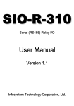
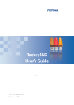
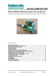
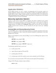
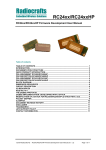
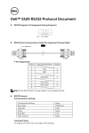
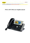
Radiocrafts
Embedded Wireless Solutions
AN014
ZigBee® simplified with RC2400-ZNM*
by Ø. Nottveit
*This application note is written for RC2400-ZNM, but all information is valid for all RC24xx
products with ZNM, including high power versions.
Introduction
ZigBee is a powerful and advanced technology, with almost unlimited possibilities. Hence it could
also be a challenge to understand and to fully utilize the technology for newcomers to ZigBee. This
application note aims to break down the barriers to ZigBee and make it more available.
This application note consists of two parts. The first part covers ZigBee basics and aim to give the
reader an introduction to ZigBee and ZigBee terminology.
The second part goes into details on how the RC2400-ZNM module can easily be used to make
the ZigBee network of your choice. Two complete examples are included to show how this can be
done.
This application note is not intended to enable readers to implement ZigBee product for
interoperability such as Smart Energy Profile compliant or Home Automation Profile compliant
products. For such implementation see AN013 as a starting point.
References, Definitions and Abbreviations
[1]:
RC24xx/RC24xxHP-ZNM User Manual
[2]:
CC2530-ZNP Interface Specification
ZigBee Basics
ZigBee is a standard for low power wireless communication built on the IEEE 802.15.4 standard.
Compared to standards as WiFi and Bluetooth, the ZigBee standard is characterized with:
- Longer range
- Multihop
- Lower power consumption
- Lower data rate
The reference protocol stack for ZigBee is shown in Figure 1
Applicaion layer (APL)
ZigBee standard
Network Layer (NWK)
Medium Access Control
(MAC)
IEEE 802.15.4 standard
Physical layer (PHY)
Figure 1 802.15.4 and ZigBee stack
©2011 Radiocrafts AS
AN014 ZigBee Simplified with RC2400-ZNM 1.0
Page 1 of 20
Radiocrafts
Embedded Wireless Solutions
AN014
ZigBee history
ZigBee is an evolving standard. The first variant was release as ZigBee 2003 and later became
ZigBee 2006. The current version is ZigBee 2007, which include both standard feature set and
PRO feature set. The PRO feature set is normally the preferred solution and also the default for
RC2400-ZNM.
Physical Radio
IEEE 802.15.4 defines 3 different radio frequency bands, 868 MHz (1 channel), 915 MHz (10
channels) and 2450 MHz (16 channels). The 2450 MHz band covering 2405-2480 MHz are by far
the most widespread and it's the only band covered by RC2400 and this application note. The
2450 MHz band supports a data rate of 250 kbps and has 16 separate channels.
A ZigBee network
Coordinator
Router
End Device
PAN = Personal
Area Network
Figure 2 A ZigBee network
Figure 2 illustrate a ZigBee network. The ZigBee network is identified with a PAN ID and extended
PAN ID. The PAN ID is 2 bytes and selected by the coordinator at start-up. The extended PAN ID
is an 8 byte number introduced in ZigBee 2007 to resolve PAN ID conflicts.
A ZigBee network consists of 3 device types
Coordinator
The Coordinator forms the network and allows other devices to join/associate
There is only one Coordinator per network.
©2011 Radiocrafts AS
AN014 ZigBee Simplified with RC2400-ZNM 1.0
Page 2 of 20
Radiocrafts
Embedded Wireless Solutions
AN014
Router
A Router is normally “on” at all time and mains power operated. It has the ability to receive a
packet and forward it in the network (= Routing). A Router can also store a packet to an associated
End Device while the End Device is sleeping.
End Device
End devices are ideal for battery operated equipment as they can sleep most of the time and only
wake up seldom to transmit data or poll for incoming messages. End devices do not have routing
capability.
Addressing
There are two types of addresses used in ZigBee
• Short address/network address
2 bytes
• MAC address/IEEE address
8 bytes
The MAC address is an 8 bytes HW related address. It is locked to a given device and the address
ranges are governed by IEEE.
The Short address is a 2 byte address only valid within a PAN. The short address for a new device
is given by the parent at the time of joining the network. To reduce overhead the short address is
the most used address type in a ZigBee network.
The short address is dynamic. A device that store its network related data in non-volatile memory
can rejoin a network and keep its short address, but if the device has forgotten its previous short
address it will be given a new address when joining.
End point
ZigBee also includes sub addressing within the same physical Radio device. This is referred to end
point (as in USB). For example a switch with two buttons but one radio. There are hence two
buttons that can be pressed and we want to identify from which button a "toggle" command is sent.
This can be done by allocating different end points to the two buttons.
End point addresses can be selected from 1 to 240.
Binding
Binding is the capability of a logically connection to an application. This allows for two devices to
connect to some sort of press-button-installation.
Security and encryption
ZigBee includes a 128 bits AES encryption on the network layer. The network key can either be
preinstalled in all devices or distributed unsecured to new devices joining the network.
More advanced security options are also available, but out of scope for this application note.
Profiles, interoperability and Cluster ID
All description above defines how two ZigBee devices can send messages between each other.
However for interoperability between devices the application messages must also be standardized.
This is done in ZigBee through Cluster library and Profiles.
This is out of scope for this application note. See application note 013 as an example for profile
interoperability.
©2011 Radiocrafts AS
AN014 ZigBee Simplified with RC2400-ZNM 1.0
Page 3 of 20
Radiocrafts
Embedded Wireless Solutions
AN014
ZigBee simplified with RC2400-ZNM
The concept of the RC2400-ZNM module is that the application is implemented in one
MCU/processor and the ZigBee Network part in the other. In RC2400-ZNM is preloaded with a
ZigBee PRO compliant stack and offers an easy to use API via UART or SPI to an external
processor. The external application processor can be of any type or brand, and the development
can be done with the tool and platform most convenient to the developer.
Application processor
RC2400-ZNM/RC2400HP-ZNM
Application
SPI/UART interface
UART/SPI
SPI/UART interface
Application Support Sublayer
ZigBee PRO stack
802.15.4 MAC
AES encryption
IEEE 802.15.4 Radio
Figure 3 ZigBee Network Module concept
For more detail on the interface between RC2400-ZNM and the host application processor see [1]
and [2]. The RC24xx-ZNM User Manual [1] should be read before reading the next part of the
application note.
Building and decoding the UART transport Frame Format
The frame format for UART transmission between the application processor and the RC2400-ZNM
are given in Figure 4.
Bytes:
1 (SOF
1
fixed)
0xFE
Bytes:
3-253
1
General Format Frame
FCS
Bytes:
2 (Command Field)
Bytes:
1
Length of
DATA field
CMD0
CMD1
0-250
DATA
Figure 4 UART frame format
©2011 Radiocrafts AS
AN014 ZigBee Simplified with RC2400-ZNM 1.0
Page 4 of 20
Radiocrafts
Embedded Wireless Solutions
AN014
The command field indicate the type of frame being transmitted. It can be a data frame, an
acknowledge frame or some sort of configuration frame. For complete overview of all available
commands see [2].
FCS: Frame-Check Sequence (Last byte of UART frame): XOR of all bytes in the General Format
Frame field
The data field can consist of several fields depending on the command. If one field consist of more
than 1 byte, the Least Significant Byte is transmitted first within the field. It is recommended to
keep the DATA length less than 128 bytes.
How to understand the examples
The examples are implemented with the PC tool ZNM-CCT. The ZNM-CCT requires access to the
modules UART via an available COM-port. Typically UART-access is obtained via an UART-toRS232 or UART-to-USB converter. The Demo Boards (DB) from Radiocrafts contains an on-board
level shifter for direct plug-in to a PC and further access to the related COM-port. A dedicated
command-text file for the examples in this application note is available.
The yellow boxes are transcript from the ZNM-CCT tool
PC-->ZNM:(The black text is information on direction of communication +
description of command sent)
GREEN IS HEX CODE SENT TO MODUEL FE 01 41 00 00 40
ZNM-->PC:
BLUE IS HEX CODE RECEIVED FROM MODULE FE 01 41 80 02 C6
Table 1 Explanation of transcript boxes
©2011 Radiocrafts AS
AN014 ZigBee Simplified with RC2400-ZNM 1.0
Page 5 of 20
Radiocrafts
Embedded Wireless Solutions
AN014
General setup - with or without storage of history
First thing is to consider if device need a total memory erase as many network and configuration
parameters could be stored from previous use. During development this is often the case.
PC-->ZNM:(SYSTEM_RESET)
FE 01 41 00 00 40
ZNM-->PC:
FE 06 41 80 02 02 00 02 03 00 C6
Reset_device
Write Configuration
->Clear device on reset
PC-->ZNM:(ZB_WRITE_CONFIGURATION->START_UP
OPTIONS->Clear device on reset)
FE 03 26 05 03 01 03 21
ZNM-->PC:
FE 01 66 05 00 62
PC-->ZNM:(SYSTEM_RESET)
FE 01 41 00 00 40
ZNM-->PC:
FE 06 41 80 02 02 00 02 03 00 C6
Reset_device
Figure 5 Clearing a device of history
©2011 Radiocrafts AS
AN014 ZigBee Simplified with RC2400-ZNM 1.0
Page 6 of 20
Radiocrafts
Embedded Wireless Solutions
AN014
Example 1- Building automation/climate control system
GPRS
ZIGBEE GW
Temp
sensor
Display/
Control panel
Heating
element
Humidity
sensor
Ventilation
FAN
Figure 6 A logical ZigBee network
Function/command
Temperature reading
From
Temp sensor
To
Display
Command ID
0x0001
Data/attributes
1 Byte
Temperature reading
Humidity reading
Temp sensor
Humidity sensor
GW
Display
0x0001
0x0002
1 Byte
1 Byte
Humidity reading
Humidity sensor
GW
0x0002
1 Byte
Set Heat level
Display
0x0003
1 Byte
Set Ventilation
Display
0x0004
1 Byte
Set temp set point
Gateway
Heating
element
Ventilation
fan
Display
0x0005
1 Byte
Set hum. set point
Gateway
Display
0x0006
1 Byte
Table 2 Commands and command ID
Devices
Device ID
0x0001
Device
version
0x01
End point in
example
0x01
Display
Input
commands
0x0001
0x0002
0x0005
0x0006
0x0001
0x0002
Output
commands
0x0003
0x0004
GW
0x0002
0x01
0x01
Temp sensor
0x0003
0x01
0x01
0x0005
0x0006
0x0001
Humidity sensor
0x0004
0x01
0x01
0x0002
Heating element
0x0005
0x01
0x01
0x0003
Ventilation fan
0x0006
0x01
0x01
0x0004
Table 3 Device types in the ZigBee network
©2011 Radiocrafts AS
AN014 ZigBee Simplified with RC2400-ZNM 1.0
Page 7 of 20
Radiocrafts
Embedded Wireless Solutions
AN014
The example consists of an environment control system. The central control element is the Display
/Control Panel. It is always present and required and hence is chosen as coordinator in the
system. Then there are two sensors, one for temperature and one for humidity. As actuators we
have similar function, one for heating and one for ventilation.
The basic function in this example network is as follows:
The sensor report to the Display/Control Panel every 5 minute, and every 1 hour to the GPRS
gateway. The Control panel have a built in set point and based on the sensor data it sends new
settings to the heating and ventilation system. The gateway sends data to a server for logging. In
addition the operator can set new temperature and humidity set points. The intelligence for
reducing temperature at night can be implemented in Display/control panel or in central server.
The setup for all device include
- Device type (Coordinator, Router, End Device)
- Encryption key usage
- Application information
(PAN ID and channel are other parameters that could be set up, but in this example we use
default)
Setting up the Coordinator
The coordinator creates the ZigBee network and hence must be started first.
The application information is registered inside the RC2400 with the ZB_APP_REGISTER
command and is mandatory. It enables automatic service discovery (not covered in this application
note).
After setup the ZigBee radio is started with a ZB_START_REQUEST command. The radio then
starts and the coordinator create a network.
©2011 Radiocrafts AS
AN014 ZigBee Simplified with RC2400-ZNM 1.0
Page 8 of 20
Radiocrafts
Embedded Wireless Solutions
AN014
PC-->ZNM:(DISPLAY_CONTROL_PANEL->Write_Keep both network
and config)
FE 03 26 05 03 01 00 22
ZNM-->PC:
FE 01 66 05 00 62
Write Configuration
->Keep Network state
and configuration
PC-->ZNM:(DISPLAY_CONTROL_PANEL->Write_Coordinator)
FE 03 26 05 87 01 00 A6
ZNM-->PC:
FE 01 66 05 00 62
Write Configuration
->Coordinator
PC-->ZNM:(DISPLAY_CONTROL_PANEL>Write_ENABLE_PRE_CFG_KEY)
FE 03 26 05 63 01 01 43
ZNM-->PC:
FE 01 66 05 00 62
Write Configuration
->Use preconfigured
Encryption key
PC-->ZNM:(DISPLAY_CONTROL_PANEL->Write_PRE_CFG_KEY)
FE 12 26 05 62 10 04 04 04 04 04 04 04 04 04 04 04 04 04
04 04 04 43
ZNM-->PC:
FE 01 66 05 00 62
Write Configuration
-> Encryption key
PC-->ZNM:(DISPLAY_CONTROL_PANEL->ZB_APP_REGISTER_DISPLAY)
FE 15 26 0A 01 FF 1F 01 00 01 00 04 01 00 02 00 05 00 06
00 02 03 00 04 00 D9
ZNM-->PC:
FE 01 66 0A 00 6D
ZB_APP_REGISTER
ZB_START_REQUEST
PC-->ZNM:(DISPLAY_CONTROL_PANEL->ZB_START_REQUEST)
FE 00 26 00 26
ZNM-->PC:
FE 00 66 00 66
ZNM-->PC:
FE 01 45 C0 09 8D //confirmation that network is created
FE 01 46 80 00 C7
Figure 7 Device setup example for coordinator
©2011 Radiocrafts AS
AN014 ZigBee Simplified with RC2400-ZNM 1.0
Page 9 of 20
Radiocrafts
Embedded Wireless Solutions
AN014
Setting up the Routers
There are several ways to ensure correct joining of the other devices in a network
(Correct means no unwanted devices joins and the wanted devices chooses the correct network)
For this example we have chosen 2 features.
- Secure joining with preconfigured network key
- Limited time window to allow joining
The coordinator was set up with a default encryption key and all joining devices must include the
same. In addition the coordinator can allow join for x seconds. This function can be connected to a
installation button at the Display/Control panel. During this time all devices with correct network key
can join.
PC-->ZNM(DISPLAY_CONTROL_PANEL>ZB_PERMIT_JOINING_FOREVER):
FE 03 26 08 FC FF FF D1
ZNM-->PC:
FE 01 66 08 00 6F
Allow join forever
Figure 8 Permit joining at Coordinator
©2011 Radiocrafts AS
AN014 ZigBee Simplified with RC2400-ZNM 1.0
Page 10 of 20
Radiocrafts
Embedded Wireless Solutions
Write Configuration
->Keep Network state
and configuration
Write Configuration
->Router
Write Configuration
->Enable preconfigured
Encryption key
AN014
PC-->ZNM:(SENSORS->Write_Keep both network and config)
FE 03 26 05 03 01 00 22
ZNM-->PC:
FE 01 66 05 00 62
PC-->ZNM:(SENSORS->Write_Router)
FE 03 26 05 87 01 01 A7
ZNM-->PC:
FE 01 66 05 00 62
PC-->ZNM:(SENSORS->Write_ENABLE_PRE_CFG_KEY)
FE 03 26 05 63 01 01 43
ZNM-->PC:
FE 01 66 05 00 62
Write Configuration
-> Encryption key
PC-->ZNM:(SENSORS->Write_PRE_CFG_KEY)
FE 12 26 05 62 10 04 04 04 04 04 04 04 04 04 04 04 04 04
04 04 04 43
ZNM-->PC:
FE 01 66 05 00 62
ZB_APP_REGISTER
PC-->ZNM:(SENSORS->ZB_APP_REGISTER_SENSOR_TEMP)
FE 0B 26 0A 01 FF 1F 03 00 01 00 00 01 01 00 C4
ZNM-->PC:
FE 01 66 0A 00 6D
ZB_START_REQUEST
PC-->ZNM:(SENSORS->ZB_START_REQUEST)
FE 00 26 00 26
ZNM-->PC:
FE 00 66 00 66
ZNM-->PC:
FE 01 45 C0 05 81 //connected to network, not autorized
FE 01 45 C0 07 83 //fully joined network
FE 01 46 80 00 C7 //start confirmation
Figure 9 Device setup example at Router ( temp sensor)
Other routes follow exact same procedure, but with different ZB_APP_REGISTER message
- Humidity sen. FE 0B 26 0A 01 FF 1F 04 00 01 00 00 01 02 00 C0
- Heating elem. FE 0B 26 0A 01 FF 1F 05 00 01 00 01 03 00 00 C0
- Vent. fan
FE 0B 26 0A 01 FF 1F 06 00 01 00 01 04 00 00 C4
- Gateway
FE 11 26 0A 01 FF 1F 02 00 01 00 02 01 00 02 00 02 05 00 06 00 DF
©2011 Radiocrafts AS
AN014 ZigBee Simplified with RC2400-ZNM 1.0
Page 11 of 20
Radiocrafts
Embedded Wireless Solutions
AN014
Service discovery/network discovery
After all devices have joined the network the devices must identify the other devices. The control
panel must identify the actuators, what type they are and what address they have. To identify
means to find their short address used for addressing data messages. The application processor
must store and hold the short address of the devices it shall send data packets to.
For the sensor it's easy to identify the Display/control unit as it is always the coordinator and have
short address 0x0000. But they also have to identify the GPRS gateway for sending hourly sensor
data.
The easiest way to do this is to identify devices by using devices with a known IEEE address. The
IEEE address is physically locked to the device and the IEEE address of a device can be known to
the application processors of the other devices. E.g. the IEEE addresses of the Ventilation fan can
be pre-programmed in the Display/Control panel application processor.
For this example it is assumed that the IEEE address for the different devices are know.
When doing the example you might want to learn the IEEE addresses of the different devices and
to do that over UART use the ZB_GET_DEVICE_INFO command.
Get Device Info -> IEEE
address for local device
Result =
0x00124B0001097E2C
PC-->ZNM:(ZB_GET_DEVICE_INFO->IEEE_addr)
FE 01 26 06 01 20
ZNM-->PC:
FE 09 66 06 01 2C 7E 09 01 00 4B 12 00 6B
Get Device Info -> Short
address for local device
Result = 0x0000
(Coordinator)
PC-->ZNM:(ZB_GET_DEVICE_INFO->Short_addr)
FE 01 26 06 02 23
ZNM-->PC:
FE 09 66 06 02 00 00 09 01 00 4B 12 00 3A
Figure 10 Reading out local information with ZB_GET_DEVICE_INFO
Based on the IEEE address the ZB_FIND_DEVICE function can be used to identify the short
addresses needed for communication.
Find device
IEEE address=
0x00124B00010F33A9
Result = 0xD03A
PC-->ZNM:(SENSORS->ZB_FIND_DEVICE):
FE 08 26 07 A9 33 0F 01 00 4B 12 00 E4
ZNM-->PC:
FE 00 66 07 61
FE 0B 46 85 01 3A D0 A9 33 0F 01 00 4B 12 00 EE
Figure 11 Identifying nodes in a network
Sending and receiving data
When all nodes know the short address of the devices they shall communicate with, the network is
completely set up and data can be sent and received with the ZB_SEND_DATA_REQUEST and
the ZB_RECEIVE_DATA_INDICATION.
©2011 Radiocrafts AS
AN014 ZigBee Simplified with RC2400-ZNM 1.0
Page 12 of 20
Radiocrafts
Embedded Wireless Solutions
ZB_SEND_DATA_REQUEST
1
1
1
2
Len(1) CMD0
CMD1 Dest..
0x09
0x26
0x03
0xNNNN
AN014
2
Com.ID
0xCCCC
1
Handle
0xHH
1
Ack
0x01
1
Radius
0x04
1
Len(2)
1
0-84
Data
0xDD
Len(1) -
Length of packet from Dest. including Data.
Dest. Com.ID -
0xNNNN = Short address of receiver. 0xFFFF is address for broadcast.
0xCCCC Command ID, (see Table 2)
Handle -
0xHH is an identifier of the sent message, so when sending more the one
message the host can identify which messages an acknowledge is received
for.
0x01 indicate that the host requests a application acknowledgement that the
packet is received by receiving application
Max number of hops for a message. 0x04 should be OK for this application.
Length of Data field = 0x01 in all our cases.
See Table 2
Ack Radius Len(2)
Data -
ZB_SEND_DATA_CONFIRM
1
1
1
1
Len(1) CMD0 CMD1 Handle
0x02
0x46
0x83
0xHH
1
Status
0x01
Len(1) -
Length of packet from Handle
Handle. -
0xHH is an identifier of the sent message, so when sending more the one
message the host can identify which messages a acknowledge is received
for.
0x00 = OK, Packet was received.
Status -
ZB_RECEIVE_DATA_INDICATION
1
1
1
2
2
Len(1) CMD0 CMD1 Source
Com.ID
0x06
0x46
0x87
0xNNNN 0xCCCC
1
Len(2)
1
1
unused
0x00
0-84
Data
0xDD
Len(1) -
Length of packet from Source. including Data.
Dest. Com.ID -
0xNNNN = Short address of receiver. 0xFFFF is address for broadcast.
0xCCCC Command ID, (see Table 2)
Handle -
0xHH is an identifier of the sent message, so when sending more the one
message the host can identify which messages a acknowledge is received
for.
0x01 indicate that the host requests a application acknowledgement that the
packet is received by receiving application
Max number of hops for a message. 0x04 should be OK for this application.
Length of Data field = 0x01 in all our cases.
See Table 2
Ack Radius Len(2)
Data -
©2011 Radiocrafts AS
AN014 ZigBee Simplified with RC2400-ZNM 1.0
Page 13 of 20
Radiocrafts
Embedded Wireless Solutions
AN014
//at temperature sensor
Send data
(temperature
reading)
Data confirm
at transmitter
(Acknowledge)
PC-->ZNM:(SENSORS>ZB_SEND_DATA_REQUEST_TEMP_12degree)
FE 09 26 03 00 00 01 00 01 01 04 01 0C
24
ZNM-->PC:
FE 00 66 03 65 FE 02 46 83 01 00 C6
//at display
ZNM-->PC:
FE 07 46 87 3A D0 01 00 01 00 0C 20
Incoming data
at receiver
Figure 12 Sending a temperature reading from sensor to display
//at Display/Control panel
Send data
(Set heat level
2)
PC-->ZNM:
FE 09 26 03 DB 39 03 00 01 01 04 01 02
CA
Data confirm
at transmitter.
(Acknowledge)
ZNM-->PC:
FE 00 66 03 65 FE 02 46 83 01 00 C6
//at heating element
Incoming data at
receiver (Set heat
level 2)
ZNM-->PC:
FE 07 46 87 00 00 03 00 01 00 02 C6
Figure 13 Sending heat level from display to heating element
©2011 Radiocrafts AS
AN014 ZigBee Simplified with RC2400-ZNM 1.0
Page 14 of 20
Radiocrafts
Embedded Wireless Solutions
AN014
//at gateway
Send data
(Set hum. level
64%)
Date confirm
at transmitter
PC-->ZNM:
FE 09 26 03 00 00 06 00 0A 01 04 01 40
64
ZNM-->PC:
FE 00 66 03 65 FE 02 46 83 0A 00 CD
//at display
Incoming data at
receiver (Set
hum. level 64%)
ZNM-->PC:
FE 07 46 87 13 CB 06 00 01 00 40 59
Figure 14 Sending set humidity level from gateway to display
©2011 Radiocrafts AS
AN014 ZigBee Simplified with RC2400-ZNM 1.0
Page 15 of 20
Radiocrafts
Embedded Wireless Solutions
AN014
Example 2- Transparent data
If you do not have the need to specify different devices and just want to send transparent data
between nodes in a network, this example shows how to make such a network. The functionality of
this network is very basic. Transparent data should be sent from one device to one or more
receivers. All application oriented information and use of the data is handled by host
microcontroller.
A setup procedure include:
- Device type (Coordinator, Router, End Device)
- Encryption key usage
- Application information
(PAN ID and channel are other parameters that could be set up, but in this example we use
default)
Node2
Node 1
Node 3
Node 4
Figure 15 A logical ZigBee network
Function/command
Send data
From
all devices
To
all devices
Command ID
0x0001
Data/attributes
N Bytes
Table 4 Commands and command ID
Devices
Device ID
Device
version
0x01
Transparent data
0x0001
device
Table 5 Device types in the ZigBee network
End point in
example
0x01
Input
commands
0x0001
Output
commands
0x0001
Setting up the Coordinator
The Coordinator starts the ZigBee network and hence must the RC2400-ZNM Coordinator be set
up first
©2011 Radiocrafts AS
AN014 ZigBee Simplified with RC2400-ZNM 1.0
Page 16 of 20
Radiocrafts
Embedded Wireless Solutions
AN014
PC-->ZNM:(TRANSPARENT_DATA->Write_Keep both network and
config)
FE 03 26 05 03 01 00 22
ZNM-->PC:
FE 01 66 05 00 62
Write Configuration
->Keep Network state
and configuration
PC-->ZNM:(TRANSPARENT_DATA->Write_Coordinator)
FE 03 26 05 87 01 00 A6
ZNM-->PC:
FE 01 66 05 00 62
Write Configuration
->Coordinator
Write Configuration
->Use preconfigured
Encryption key
PC-->ZNM:(TRANSPARENT_DATA->Write_ENABLE_PRE_CFG_KEY)
FE 03 26 05 63 01 01 43
ZNM-->PC:
FE 01 66 05 00 62
Write Configuration
-> Encryption key
PC-->ZNM:(TRANSPARENT_DATA->Write_PRE_CFG_KEY)
FE 12 26 05 62 10 04 04 04 04 04 04 04 04 04 04 04 04 04
04 04 04 43
ZNM-->PC:
FE 01 66 05 00 62
ZB_APP_REGISTER
PC-->ZNM:(TRANSPARENT_DATA->ZB_APP_REGISTER_DISPLAY)
FE 15 26 0A 01 FF 1F 01 00 01 00 04 01 00 02 00 05 00 06
00 02 03 00 04 00 D9
ZNM-->PC:
FE 01 66 0A 00 6D
ZB_START_REQUEST
PC-->ZNM:(TRANSPARENT_DATA->ZB_START_REQUEST)
FE 00 26 00 26
ZNM-->PC:
FE 00 66 00 66
ZNM-->PC:
FE 01 45 C0 09 8D //confirmation that network is created
FE 01 46 80 00 C7
Figure 16 Device setup example for coordinator
©2011 Radiocrafts AS
AN014 ZigBee Simplified with RC2400-ZNM 1.0
Page 17 of 20
Radiocrafts
Embedded Wireless Solutions
AN014
Setting up the Routers
In Figure 17 it is shown the required setup for a Router, including network joining.
For controlling joining of new routers to the network, please see page 10
Write Configuration
->Keep Network state
and configuration
Write Configuration
->Router
Write Configuration
->Enable preconfigured
Encryption key
PC-->ZNM:(TRANSPARENT_DATA->Write_Keep both network and
config)
FE 03 26 05 03 01 00 22
ZNM-->PC:
FE 01 66 05 00 62
PC-->ZNM:(TRANSPARENT_DATA->Write_Router)
FE 03 26 05 87 01 01 A7
ZNM-->PC:
FE 01 66 05 00 62
PC-->ZNM:(TRANSPARENT_DATA->Write_ENABLE_PRE_CFG_KEY)
FE 03 26 05 63 01 01 43
ZNM-->PC:
FE 01 66 05 00 62
Write Configuration
-> Encryption key
PC-->ZNM:(TRANSPARENT_DATA->Write_PRE_CFG_KEY)
FE 12 26 05 62 10 04 04 04 04 04 04 04 04 04 04 04 04 04
04 04 04 43
ZNM-->PC:
FE 01 66 05 00 62
ZB_APP_REGISTER
PC-->ZNM:(TRANSPARENT_DATA->ZB_APP_REGISTER_GENERAL)
FE 0D 26 0A 01 FF 1F 01 00 01 00 01 01 00 01 01 00 C4
ZNM-->PC:
FE 01 66 0A 00 6D
ZB_START_REQUEST
PC-->ZNM:(TRANSPARENT_DATA->ZB_START_REQUEST)
FE 00 26 00 26
ZNM-->PC:
FE 00 66 00 66
ZNM-->PC:
FE 01 45 C0 05 81 //connected to network, not autorized
FE 01 45 C0 07 83 //fully joined network
FE 01 46 80 00 C7 //start confirmation
Figure 17 Device setup example at Router (transparent data device)
Identifying/finding nodes
For how to find devices in a network based on the IEEE address see page 12.
©2011 Radiocrafts AS
AN014 ZigBee Simplified with RC2400-ZNM 1.0
Page 18 of 20
Radiocrafts
Embedded Wireless Solutions
AN014
Sending and receiving transparent data.
When all nodes know the short address of the devices they shall communicate with, the network is
completely set up and data can be sent and received with the ZB_SEND_DATA_REQUEST and
the ZB_RECEIVE_DATA_INDICATION. Example of communication of the three bytes "AC E0 07"
is illustrated below:
Host A short address: 0x0000
HOST A
Host B short address: 0x9B20
RC2400-ZNM
ZB_SEND_DATA_REQUEST:
FE 0B 26 03 20 9B 01 00 01 01 04 03 AC E0 07 D8
RC2400-ZNM
HOST B
ZB_IMCOMING
FE 09 46 87 00 00 01 00 03 00 AC E0 07 81
Short Address of
sender
Data sent
Short Address of
receiver
Length of Data
Data received
Length of Data
Handle: Indentification of packet
ACKNOWLEDGE:
HOST A
RC2400-ZNM
RC2400-ZNM
ZB_SEND_DATA_CONFIRM:
FE 02 46 83 01 00 C6
Handle: Indentification of packet
In order for the host controllers to identify the payload in both directions they must discard the
overhead bytes added before- and after the Data field. The overhead bytes give valuable addressand information data which can be used for addressed communication.
Remarks
This application note has given a brief introduction to ZigBee and showed how easy it can be to
build a ZigBee network with RC2400-ZNM. However it has only revealed a small part of the
powerful functionality within RC2400-ZNM and ZigBee PRO. For more detailed information and
complete overview of the features within RC2400-ZNM see the RC24xx-ZNM User Manual and the
CC2530-ZNP interface specification.
©2011 Radiocrafts AS
AN014 ZigBee Simplified with RC2400-ZNM 1.0
Page 19 of 20
Radiocrafts
Embedded Wireless Solutions
Document Revision History
Document Revision
1.0
AN014
Changes
First release
Disclaimer
Radiocrafts AS believes the information contained herein is correct and accurate at the time of this printing. However,
Radiocrafts AS reserves the right to make changes to this product without notice. Radiocrafts AS does not assume any
responsibility for the use of the described product; neither does it convey any license under its patent rights, or the rights of
others. The latest updates are available at the Radiocrafts website or by contacting Radiocrafts directly.
As far as possible, major changes of product specifications and functionality, will be stated in product specific Errata Notes
published at the Radiocrafts website. Customers are encouraged to check regularly for the most recent updates on
products and support tools.
Trademarks
ZigBee is a registered trademark of the ZigBee alliance.
© 2011 Radiocrafts AS. All rights reserved.
Contact Information
Web site: www.radiocrafts.com
Address:
Radiocrafts AS
Sandakerveien 64
NO-0484 OSLO
NORWAY
Tel:
+47 4000 5195
Fax:
+47 22 71 29 15
E-mail: [email protected]
[email protected]
[email protected]
©2011 Radiocrafts AS
AN014 ZigBee Simplified with RC2400-ZNM 1.0
Page 20 of 20