1
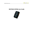
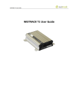
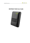
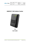
MEITRACK T311 User Guide MEITRACK T311 User Guide MEITRACK T311 User Guide Change History File Name MEITRACK T311 User Guide Created By Kyle Lv Project T311 Creation Date 2014-08-01 Update Date 2015-09-30 Subproject User Guide Total Pages 17 Version V1.6 Confidential External Documentation Copyright © 2015 Meitrack Group All rights reserved. -2- MEITRACK T311 User Guide Contents 1 Copyright and Disclaimer...............................................................................................................................................................- 4 2 Product Overview ..........................................................................................................................................................................- 4 3 Product Function and Specifications .............................................................................................................................................- 4 3.1 Product Function ................................................................................................................................................................- 4 3.1.1 Position Tracking ......................................................................................................................................................- 4 3.1.2 Anti-Theft .................................................................................................................................................................- 4 3.1.3 Other Functions .......................................................................................................................................................- 5 3.1.4 Functions of Optional Accessories ...........................................................................................................................- 5 3.2 Specifications ......................................................................................................................................................................- 5 4 T311 and Accessories ....................................................................................................................................................................- 6 5 First Use .........................................................................................................................................................................................- 6 5.1 Installing the SIM Card ........................................................................................................................................................- 6 5.2 LED Indicator.......................................................................................................................................................................- 7 5.3 Configured by Computer ....................................................................................................................................................- 7 5.4 Tracking by Mobile Phone...................................................................................................................................................- 8 5.5 Common SMS Commands ..................................................................................................................................................- 9 5.5.1 Setting a Function Phone Number ...........................................................................................................................- 9 5.5.2 Arming/Disarming .................................................................................................................................................- 10 5.6 Remote Control Functions ................................................................................................................................................- 10 5.6.1 Definitions of RF Remote Control Keys ..................................................................................................................- 10 5.6.2 RF Remote Control Code Matching Function .........................................................................................................- 11 6 MS03 Tracking System .................................................................................................................................................................- 11 7 Installing the T311 .......................................................................................................................................................................- 12 7.1 (Optional) Installing the GPS Antenna ..............................................................................................................................- 12 7.2 Installing an I/O Cable .......................................................................................................................................................- 12 7.2.1 Port Definition .......................................................................................................................................................- 12 7.2.2 Port Pictures ..........................................................................................................................................................- 13 7.2.3 Motorcycle Wiring Diagram ...................................................................................................................................- 14 7.2.3.1 Motorcycle DC Ignition Wiring Diagram .....................................................................................................- 14 7.2.3.2 Motorcycle AC Ignition Wiring Diagram .....................................................................................................- 15 7.2.3.3 Positive/Negative Start Wiring Diagram .....................................................................................................- 16 7.2.4 Electric Vehicle Wiring Diagram .............................................................................................................................- 17 7.3 Mounting the T311 ...........................................................................................................................................................- 17 - Copyright © 2015 Meitrack Group All rights reserved. -3- MEITRACK T311 User Guide 1 Copyright and Disclaimer Copyright © 2015 MEITRACK. All rights reserved. and are trademarks that belong to Meitrack Group. The user manual may be changed without notice. Without prior written consent of Meitrack Group, this user manual, or any part thereof, may not be reproduced for any purpose whatsoever, or transmitted in any form, either electronically or mechanically, including photocopying and recording. Meitrack Group shall not be liable for direct, indirect, special, incidental, or consequential damages (including but not limited to economic losses, personal injuries, and loss of assets and property) caused by the use, inability, or illegality to use the product or documentation. 2 Product Overview The T311 is an anti-theft GPS tracking device specially designed for motorcycles and electric vehicles. The T311 is equipped with a wireless remote control and a buzzer, so that vehicle arming, disarming, and keyless start can be implemented. In arming state, if a vehicle is faulty, the buzzer will generate an alarm, and thus the engine is stopped and the vehicle is locked to prevent stealing. 3 Product Function and Specifications 3.1 Product Function 3.1.1 Position Tracking GPS + GSM dual-module tracking Real-time location query Track by time interval Track by distance Track by mobile phone Speeding alarm Direction change alarm 3.1.2 Anti-Theft (Optional) SOS alarm by remote control Arming/Disarming Towing alarm (Optional) Electric vehicle anti lock motor (Optional) Remote engine stop GPS blind spot alarm External power cut-off alarm Buzzer alarm Geo-fence Copyright © 2015 Meitrack Group All rights reserved. -4- MEITRACK T311 User Guide 3.1.3 Other Functions SMS/GPRS (TCP/UDP) communication (Meitrack protocol) Built-in 8 MB buffer for driving trace recording Low battery alarm Water resistant IP65 (Optional) Electric vehicle keyless drive (Optional) Motorcycle keyless start/flameout (Optional) Panic button 3.1.4 Functions of Optional Accessories Accessory Function Arming/Disarming Wireless remote control Keyless start/flameout Keyless drive Panic button External GPS antenna Improve the GPS signal reception. 3.2 Specifications Item Specifications GSM frequency band GSM 850/900/1800/1900 MHz GPS sensitivity -162 dB Positioning accuracy 10m Dimension 86 mm x 65 mm x 25 mm Weight 165g Coordinate system WGS-84 Input voltage DC 11–90 V/1.5 A Built-in battery 730 mAh/3.7 V Normal power consumption 60 mAh Operating temperature -22°C to 55°C GSM antenna Internal antenna GPS antenna Internal antenna (the side with the logo facing upwards) (Optional) External antenna Built-in memory chip 8 MB Sensor 3D acceleration sensor (for wake-up by vibration and towing alarms) Wireless remote control RF 433 MHz 1 positive output 1 input for motorcycle flameout (upper flameout cable) Port 1 output for motorcycle flameout (lower flameout cable) 1 output for motorcycle start or input for electric vehicle motor start detection 1 input for motorcycle positive/negative start 1 output for a buzzer alarm Copyright © 2015 Meitrack Group All rights reserved. -5- MEITRACK T311 User Guide 1 USB port 1 wireless remote control antenna 1 negative terminal connection cable 4 T311 and Accessories T311 and standard accessories: T311 with a built-in battery Motorcycle cable Buzzer USB cable CD 3M double sided tape Electric vehicle cable Optional accessories: External GPS antenna Wireless remote control 5 First Use 5.1 Installing the SIM Card 1. Remove the back cover. Turn off the device. With the back panel facing you, use the mini screwdriver to remove the two screws to release the back cover. Then lift up the back cover from the notch at the bottom of the device. 2. Insert the SIM card. Copyright © 2015 Meitrack Group All rights reserved. -6- MEITRACK T311 User Guide Gently push the SIM card into the slot until you hear a click with the gold-plated contacts facing down. Note: Before inserting the SIM card, turn off the device. Ensure that the PIN lock of the SIM card is closed properly, and the SIM card has sufficient balance and has subscribed the call ID service. If you want to use the GPRS function, learn about the SIM card GPRS charging first. 5.2 LED Indicator Power button GPS indicator (blue) GSM indicator (green) To start the T311, press and hold down the power button for 3s to 5s, or connect the T311 to external power supply. GPS Indicator (Blue) Steady on One button is pressed or one input is activated. Blink (0.1s on) The tracker is being initialized or the battery power is low. Blink (0.1s on and 2.9s off) A GPS signal is received. Blink (3s on) No GPS signal is received. GSM Indicator (Green) Steady on A call is coming in or a call is being made. Blink (0.1s on) The tracker is being initialized. Blink (0.1s on and 2.9s off) A GSM signal is received. Blink (3s on) No GSM signal is received. 5.3 Configured by Computer This section describes how to use Meitrack Manager to configure the T311 on a computer. Procedure: 1. Install the USB-to-serial cable (PL2303) driver and Meitrack Manager. 2. Connect the T311 to a PC by using the USB-to-serial cable. Copyright © 2015 Meitrack Group All rights reserved. -7- MEITRACK T311 User Guide 3. Run Meitrack Manager, then the following dialog box will appear: Turn on the device, then Meitrack Manager will detect the device model automatically and the parameter page will appear accordingly. For details about Meitrack Manager, see the MEITRACK Manager User Guide. 5.4 Tracking by Mobile Phone This section describes how to query the current location of the T311, ensuring that the GPS is working normally. Call the SIM card phone number that is used in the T311, and hang up after the dial tone rings 2-3 times. Note: If an authorized phone number was set by SMS command A71, only this phone number can receive SMS reports. A location SMS is received. Click the link in the SMS to query the location. SMS example: Now,110727 02:48,V,16,23Km/h,61%,http://maps.google.com/maps?f=q&hl=en&q=22.540103,114.082329 The following table describes the SMS format: Parameter Description Now Indicates the current location. Copyright © 2015 Meitrack Group All rights reserved. Remarks SMS header: indicates the alarm type. For details about the SMS header, see the MEITRACK -8- MEITRACK T311 User Guide SMS Protocol and MEITRACK GPRS Protocol. 110727 02:48 V Indicates the date and time in YYMMDD hh:mm format. The GPS is invalid. None A = Valid V = Invalid Value: 1–32 16 Indicates the GSM signal strength. The larger the value is, the stronger the signal is. If the value is greater than 12, GPRS reaches the normal level. 23Km/h Indicates the speed. Unit: km/h 61% Indicates the remaining battery power. None http://maps.google.com/ This is a map link. maps?f=q&hl=en&q=22.5 Latitude: 22.540103 40103,114.082329 Longitude: 114.082329 None If there is no valid GPS available, the tracker will reply the most recent valid position. If your mobile phone does not support HTTP, enter the latitude and longitude on Google Maps to query a location. 5.5 Common SMS Commands 5.5.1 Setting a Function Phone Number SMS sending: 0000,A71,Phone number 1,Phone number 2,Phone number 3 SMS reply: IMEI,A71,OK Description: Phone number: A function phone number has a maximum of 16 bytes. If no phone numbers are set, leave them blank. Phone numbers are empty by default. Phone number 1/2/3: SOS phone numbers. When you call the tracker by using these phone numbers, SMSs of locations, geo-fence alarms, low power alarms, and speeding alarms are received, and calls and SMSs of car towing and stealing alarms are received. If all function phone numbers need to be deleted, send 0000,A71. When the SOS button is pressed, the tracker dials phone numbers 1, 2, and 3 in sequence. The tracker stops dialing when a phone number responds. Copyright © 2015 Meitrack Group All rights reserved. -9- MEITRACK T311 User Guide Example: 0000,A71,13811111111,13822222222,13833333333 Reply: 353358017784062,A71,OK 5.5.2 Arming/Disarming SMS sending: 0000,B21,Status SMS reply: IMEI,B21,OK Description: When Status is 1, enable the arming function. In arming state, activating the engine is an unauthorized operation. If the operation is performed, the tracker will send an alarm SMS to the preset authorized phone number. When Status is 0, disable the arming function. In disarming state, all anti-theft alarms will be cleared. For details about SMS commands, see the MEITRACK SMS Protocol. Note: 1. The default SMS command password is 0000. You can change the password by using Meitrack Manager and SMS commands. 2. The device can be configured by SMS commands with a correct password. After an authorized phone number is set, only the authorized phone number can receive the preset SMS event report. 5.6 Remote Control Functions 5.6.1 Definitions of RF Remote Control Keys Current Vehicle State Function Key Description Press "Arm" key when the engine is off; and the tracker will confirm Disarming state/ACC OFF arming with a "beep" sound. While under this stage, if the vehicle is Arm Key Arming state Start state vibrated or attempted to start; the stealing alarm will be generated. If the buzzer sounds “beep” twice, the arming state will be disabled. Disarm Key Press "Disarm" key to cut off the vehicle. Press the key twice to start the vehicle. If the vehicle is started by ACC OFF using the remote control in the arming state, the arming state will be Start Key Press and hold down ‘Horn’ key for 2 seconds; an SMS/GPRS SOS Any status ACC OFF automatically disabled. alarm will be generated. Horn Key The buzzer will sound for 4 seconds to alert the location of the vehicle. Copyright © 2015 Meitrack Group All rights reserved. - 10 - MEITRACK T311 User Guide 5.6.2 RF Remote Control Code Matching Function If the remote control does not match the tracker, match the code manually. There are the following two code matching modes: 1. ACC code matching mode a) In disarming state, turn the vehicle key in the lock for 8 times from ACC OFF to ACC ON, and stay on the ACC ON state. After 3s, the buzzer will sound “bi” 3 times to enter the code matching state. Note that if it takes more than 3s to turn the key twice, the number of key turning times will recount. b) Press any key on one remote control. If the buzzer sounds 3 times, the code is matched successfully. Then press any key on the other remote control, the buzzer sounds 3 times. In this way, you can exit the code matching state. If a same remote control is pressed twice, code matching performed later for other remote controls does not take effect. c) The code matching must be completed within 20s. Otherwise, the code matching state exits automatically. d) When more than one remote controls are implemented code matching, if a same remote control is pressed twice, code matching performed later for other remote controls does not take effect. 2. Command code matching mode a) Send the SMS/GPRS command 000,B24,1 to enter the code matching state. After the tracker receives the command, the buzzer will sound 3 times. b) If you have two remote controls, press any key on one remote control. If the buzzer sounds "bi" 3 times, the code is matched successfully. Then press any key on the other remote control, the buzzer sounds 3 times. In this way, you can exit the code matching state. c) The code matching must be completed within 20s. Otherwise, the code matching state exits automatically. d) When more than one remote controls are implemented code matching, if a same remote control is pressed twice, code matching performed later for other remote controls does not take effect. 6 MS03 Tracking System Visit http://ms03.trackingmate.com, enter the user name and password, and log in to the MS03. (Purchase the login account from your provider.) For more information about how to add a tracker, see the MEITRACK GPS Tracking System MS03 User Guide (chapter 4 "Getting Started"). The MS03 supports the following functions: Track by time interval or distance. Query historical traces. Set polygon geo-fences. Bind driver and vehicle information. View various reports. Send commands in batches. Support OTA updates. For details, see the MEITRACK GPS Tracking System MS03 User Guide. Copyright © 2015 Meitrack Group All rights reserved. - 11 - MEITRACK T311 User Guide 7 Installing the T311 7.1 (Optional) Installing the GPS Antenna Connect the GPS antenna to the GPS port on the side panel of the tracker. It is recommended that the antenna should face up to the sky and the antenna side with words should face downwards. Secure the antenna by using double sided tapes. Note: Do not install the GPS antenna at a place with metals. 7.2 Installing an I/O Cable 7.2.1 Port Definition The I/O cable includes the power cable, positive and negative input, and output. Port Color Description Positive power supply Red Connected to the positive wire, 11–90V, 10 A fuse. Black Connected to the GND, negative wire. Negative power supply (GND) Connected to the positive output line (that is, the ACC cable) of a lock motor on an electric vehicle or motorcycle. Used to detect whether the vehicle key Positive output/Lock motor Orange switch is turned on or whether to output positive electricity by simulating the original lock motor when the vehicle is started remotely. For motorcycle: Connected to the positive output cable. For electric vehicle: Connected to the lock motor cable. Upper flameout cable Pink For motorcycle: remote flameout (Refer to the section 7.2.3 "Motorcycle Wiring Diagram.") For motorcycle: remote flameout Lower flameout cable Grey For electric vehicle: anti lock motor. (Note: When the device is connected to an electric vehicle, the electric vehicle sheathed wire is blue.) For motorcycle: remote start. For electric vehicle: ACC detection. For positive start motorcycle: When the green cable is connected to the red Start cable Blue cable (the positive wire), positive current flows through to start the motorcycle. For negative start motorcycle: When the green cable is connected to the black wire (GND), negative current drains to start the motorcycle. (Refer to the section 7.2.3.3 "Positive/Negative Start Wiring Diagram.") Buzzer output (PWM) cable 1 Brown Buzzer plug: connects to the buzzer. Copyright © 2015 Meitrack Group All rights reserved. - 12 - MEITRACK T311 User Guide Buzzer output (PWM) cable 2 For positive start motorcycle: When the green cable is connected to the red cable (the positive wire), positive current flows through to start the motorcycle. Positive/Negative selectable start cable Green For negative start motorcycle: When the green cable is connected to the black wire (GND), negative current drains to start the motorcycle. If the device is installed on an electric vehicle, ignore the green cable. (Refer to the section 7.2.3 "Motorcycle Wiring Diagram" and 7.2.4 "Electric Vehicle Wiring Diagram.") GDN Remote control antenna USB232 cable Black Connected to the GND cable or the vehicle body. Baby blue RF remote control antenna for signal receiving Bold black Connected to the USB232 port. Used for parameter configuration and program upgrade. 7.2.2 Port Pictures Motorcycle cable Electric vehicle cable Buzzer output USB232 port Copyright © 2015 Meitrack Group All rights reserved. Remote control antenna - 13 - MEITRACK T311 User Guide 7.2.3 Motorcycle Wiring Diagram 7.2.3.1 Motorcycle DC Ignition Wiring Diagram Turn the switch to the leftmost position (DC ignition mode): Copyright © 2015 Meitrack Group All rights reserved. - 14 - MEITRACK T311 User Guide 7.2.3.2 Motorcycle AC Ignition Wiring Diagram Turn the switch to the rightmost position (AC ignition mode): Copyright © 2015 Meitrack Group All rights reserved. - 15 - MEITRACK T311 User Guide 7.2.3.3 Positive/Negative Start Wiring Diagram Referring to the above diagrams, if positive current flows through to start the motorcycle, connect the green cable to the red cable; if negative current drains to start the motorcycle, connect the green cable to the black cable. (Green, red and black cables are from the tracker.) If the device is installed on an electric vehicle, ignore the green cable. Copyright © 2015 Meitrack Group All rights reserved. - 16 - MEITRACK T311 User Guide 7.2.4 Electric Vehicle Wiring Diagram 7.3 Mounting the T311 Use cable ties to fasten the T311 on the motorcycle. Note: The device side with the Meitrack logo faces upwards to get better GPS signal. If you have any questions, do not hesitate to email us at [email protected]. Copyright © 2015 Meitrack Group All rights reserved. - 17 -