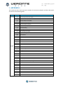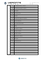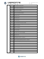
1
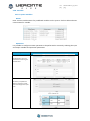
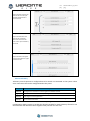
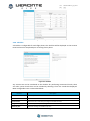
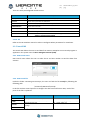
cod: pag: Software User Manual Veronte-SUM-v1.3.6_2.docx 1/53 cod: pag: Veronte-SUM-v1.3.6_2.docx 2/53 Table of Contents 1. OVERVIEW ......................................................................................................................................... 5 1.1. SYSTEM OVERVIEW................................................................................................................................. 5 1.2. VERONTE PIPE INTERFACE ........................................................................................................................ 6 2. INSTALLATION .................................................................................................................................... 7 2.1. VERONTE PIPE INSTALLATION .................................................................................................................... 7 2.2. UPGRADE ............................................................................................................................................. 7 2.3. PC CONNECTION .................................................................................................................................... 8 3. SETUP................................................................................................................................................. 9 3.1. VERONTE PIPE ..................................................................................................................................... 10 3.2. VERONTE AUTOPILOT ............................................................................................................................ 11 3.3. TUNNEL UDP ...................................................................................................................................... 34 4. WORKSPACE CONFIGURATION ........................................................................................................ 36 4.1. MAP DISPLAY ...................................................................................................................................... 36 4.2. GAUGE DISPLAY ................................................................................................................................... 38 4.3. PRIMARY FLIGHT DISPLAY ...................................................................................................................... 38 4.4. STICK ................................................................................................................................................. 39 4.5. CAM .................................................................................................................................................. 39 4.6. TERRAIN ............................................................................................................................................. 40 5. FLIGHT PLAN .................................................................................................................................... 41 5.1. WAYPOINT CREATION ........................................................................................................................... 41 5.2. MAPPING TOOL ................................................................................................................................... 43 6. OPERATION ...................................................................................................................................... 45 7. LOG .................................................................................................................................................. 47 8. POST-FLIGHT .................................................................................................................................... 48 8.1. DATA EXPORT ...................................................................................................................................... 48 8.2. TOUR ................................................................................................................................................. 48 9. APPENDIX 1...................................................................................................................................... 49 Figures and Tables FIGURE 1: VERONTE SYSTEM OVERVIEW ..................................................................................................... 5 FIGURE 2: INTERFACE ................................................................................................................................... 6 FIGURE 3: COMPATIBILITY MODE................................................................................................................. 7 FIGURE 4: COMPATIBILITY MODE................................................................................................................. 7 FIGURE 5: SETUP TOOLBAR .......................................................................................................................... 9 FIGURE 6: VERONTE PIPE - PREFERENCES .................................................................................................. 10 FIGURE 7: VERONTE PIPE - UNITS ............................................................................................................... 10 FIGURE 8: SETUP - VERONTE ...................................................................................................................... 11 FIGURE 9: SETUP – VERONTE - CUSTOM .................................................................................................... 11 FIGURE 10: SETUP – VERONTE - POSITION ................................................................................................. 11 FIGURE 11: SETUP – VERONTE – ADVANCED ORIENTATION ...................................................................... 12 FIGURE 12: SETUP – VERONTE – CONNECTIONS ........................................................................................ 12 FIGURE 13: SETUP – DEVICES – FREQUENCY .............................................................................................. 13 FIGURE 14: SETUP – DEVICES - ACTUATORS ............................................................................................... 14 FIGURE 15: SIGN CONVENTION .................................................................................................................. 14 FIGURE 16: SETUP – DEVICES –ENCODER ................................................................................................... 15 cod: pag: Veronte-SUM-v1.3.6_2.docx 3/53 FIGURE 17: ENCODER CONFIGURATION WIZARD ...................................................................................... 16 FIGURE 18: SETUP – DEVICES – SENSOR – ENCODER ................................................................................. 16 FIGURE 19: MAGNETOMETER CALIBRATION PROCEDURE ......................................................................... 17 FIGURE 20: MAGNETOMETER CALIBRATION VALUES ................................................................................ 17 FIGURE 21: SETUP – DEVICES –MAGNETO NAVIGATION ........................................................................... 17 FIGURE 22: SETUP – DEVICES –VARCONSUMER......................................................................................... 18 FIGURE 23: SETUP – DEVICES – DYNAMIC PRESSURE ................................................................................ 18 FIGURE 24: SETUP – DEVICES – RADAR ALTIMETER ................................................................................... 19 FIGURE 25: SETUP – DEVICES –GPS ............................................................................................................ 19 FIGURE 26: SETUP – DEVICES –STATIC PRESSURE ...................................................................................... 19 FIGURE 27: TEST STICK CONFIGURATION ................................................................................................... 20 FIGURE 28: STICK CONFIGURATION ........................................................................................................... 20 FIGURE 29: VIRTUAL STICK CONFIGURATION ............................................................................................. 21 FIGURE 30: GPIO MANAGER ....................................................................................................................... 21 FIGURE 31: PAYLOAD CONFIGURATION ..................................................................................................... 22 FIGURE 32: SETUP - CONTROL .................................................................................................................... 22 FIGURE 33: PID ARCHITECTURE .................................................................................................................. 26 FIGURE 34: PID DIAGRAM .......................................................................................................................... 26 FIGURE 35: PID ELEMENTS ......................................................................................................................... 27 FIGURE 36: COPY OPTION .......................................................................................................................... 28 FIGURE 37: FIXED VALUE SETTINGS ............................................................................................................ 28 FIGURE 38: ARCADE MODE SETTINGS ........................................................................................................ 28 FIGURE 39: MODE SETTINGS ...................................................................................................................... 29 FIGURE 40: NAVIGATION PARAMETERS ..................................................................................................... 29 FIGURE 41: AUTOMATION DISPLAY............................................................................................................ 30 FIGURE 42: VARIABLE NAME CUSTOMIZATION ......................................................................................... 31 FIGURE 43: SETUP – TELEMETRY ................................................................................................................ 33 FIGURE 44: CHECKLIST ................................................................................................................................ 33 FIGURE 45: UDP TUNNEL CONFIG .............................................................................................................. 34 FIGURE 46: TELEMETRY TOOLBAR .............................................................................................................. 36 FIGURE 47: MAP SETTINGS ......................................................................................................................... 37 FIGURE 48: BACKGROUND IMAGE EXAMPLE ............................................................................................. 37 FIGURE 49: BACKGROUND IMAGE POSITIONING ....................................................................................... 37 FIGURE 50: BACKGROUND IMAGE MANAGER ........................................................................................... 37 FIGURE 51: GAUGE CONFIGURATION ........................................................................................................ 38 FIGURE 52:PFD CONFIGURATION ............................................................................................................... 38 FIGURE 53:PFD EXAMPLES ......................................................................................................................... 39 FIGURE 54: STICK CONFIGURATION ........................................................................................................... 39 FIGURE 55: STICK DISPLAY .......................................................................................................................... 39 FIGURE 56:CAMERA DISPLAY CONFIGURATION ......................................................................................... 40 FIGURE 57: TERRAIN PROFILE CONFIGURATION ........................................................................................ 40 FIGURE 58: MISSION TOOLBAR .................................................................................................................. 41 FIGURE 59: WAYPOINT PARAMETERS ........................................................................................................ 42 FIGURE 60: POLYGON CREATION ............................................................................................................... 42 FIGURE 61: MISSION ................................................................................................................................... 43 FIGURE 62: MAPPING MISSION 1 ............................................................................................................... 43 FIGURE 63: MAPPING CREATION................................................................................................................ 43 FIGURE 64: MAPPING PARAMETERS .......................................................................................................... 44 FIGURE 65: MAPPING MISSION .................................................................................................................. 44 FIGURE 66: SIDE PANEL .............................................................................................................................. 45 FIGURE 67: VERONTE PANEL ...................................................................................................................... 45 FIGURE 68: LOG TOOLBAR .......................................................................................................................... 47 FIGURE 69: REPORT INFORMATION ........................................................................................................... 47 FIGURE 70: POST FLIGHT TOOLBAR ............................................................................................................ 48 FIGURE 71: DATA EXPORT .......................................................................................................................... 48 cod: pag: Veronte-SUM-v1.3.6_2.docx 4/53 TABLE 1: SETUP TOOLBAR ............................................................................................................................ 9 TABLE 2: SETUP TABS ................................................................................................................................... 9 TABLE 3: VERONTE PIPE PREFERENCES ........................................................................................................ 9 TABLE 4: SETUP – VERONTE ....................................................................................................................... 11 TABLE 5: SETUP – CONNECTIONS ............................................................................................................... 12 TABLE 6: SETUP – DEVICES - ACTUATORS................................................................................................... 14 TABLE 7: ACTUATOR CONFIGURATION ...................................................................................................... 15 TABLE 8: SETUP – DEVICES -ENCODER ....................................................................................................... 15 TABLE 9: SETUP – DEVICES –MAGNETO NAVIGATION ............................................................................... 18 TABLE 10: SETUP – DEVICES – DYNAMIC PRESSURE .................................................................................. 18 TABLE 11: SETUP – DEVICES – STATIC PRESSURE ....................................................................................... 19 TABLE 12: SETUP CONTROL ........................................................................................................................ 22 TABLE 13: GUIDANCE SETTINGS ................................................................................................................. 23 TABLE 14: CONTROL TYPE .......................................................................................................................... 26 TABLE 15: PID CONTROL STATUS................................................................................................................ 26 TABLE 16: PID ELEMENTS ........................................................................................................................... 27 TABLE 17: AUTOMATION ACTIONS ............................................................................................................ 30 TABLE 18: AUTOMATION ACTIVATION EVENTS ......................................................................................... 30 TABLE 19: TELEMETRY CONFIGURATION ................................................................................................... 32 TABLE 20: CHECKLIST CONFIGURATION ..................................................................................................... 33 TABLE 21: PRECONFIGURED CHECKLIST ..................................................................................................... 34 TABLE 22: TELEMETRY TOOLBAR ................................................................................................................ 36 TABLE 23: WORKSPACE CREATION ............................................................................................................. 36 TABLE 24: STICK CONFIGURATION ............................................................................................................. 39 TABLE 25: MISSION TOOLBAR .................................................................................................................... 41 TABLE 26: WAYPOINT ................................................................................................................................. 42 TABLE 27: POST FLIGHT TOOLBAR .............................................................................................................. 48 Acronyms HUM ID PFD REC RPAS SUM SRS UAV WP Hardware User Manual Identification Primary Flight Display Record Remotely Piloted Aircraft Software User Manual Software Requirements Specifications Unmanned Aircraft Vehicle Waypoint cod: pag: Veronte-SUM-v1.3.6_2.docx 5/53 1. OVERVIEW 1.1. System Overview Veronte Pipe is the software designed for operating any Veronte powered platform. Users achieve a combination of easy-to-use application, real-time response and, firstly, safe operations. It has been developed using software standard model of IEEE STD 830-1998, Recommended Practice for Software Requirements Specifications (SRS) and STANAG 4671 documentation, subpart I about UAV Control Stations adapted to Veronte system. Supported operations include: Telemetry: View real time on-board UAV metrics, such as sensors, actuators and control states. Telecommand: Support for all synchronous operator control commands that can be sent to the flight segment, e.g. operational mode switch, mission management, payload control and so on. Mission design: Configure missions with waypoint definition, payload target definition and coverage analysis. Mission analysis: Rebuild all recorded data from a previous flight and generate plots and reports. Configuration: Edit RPAS settings, such as servo trim, interface/port management and so on. Multiple Users: One or more operators can work simultaneously. Veronte powered systems have two main elements, air and ground segments. Figure 1: Veronte System Overview Veronte Air includes any necessary element to; communicate with ground segment, take flight measures, control the aircraft and control the payload. Veronte Ground redirects stick and PC data to the air segment, and manages bidirectional communications between Veronte Pipe and Veronte Air. cod: pag: Veronte-SUM-v1.3.6_2.docx 6/53 1.2. Veronte Pipe Interface Workspace on Veronte Pipe is distributed as shown on Figure 2: Figure 2: Interface 1: Main display 2: Menu 3: Veronte Panel 4: Veronte position 5: Mission 6: Telemetry displays 7: Side panel Each section has the following functions: 1 - Main Display: Displays a selectable background map or a plain colour together with most important mission data. 2 - Menu: User: Manage user preferences. Setup: Configure Pipe and Veronte autopilot. Workspace: Select the way flight information is displayed. Mission: Create and edit missions. Log: View operation data log and introduce custom events. Post Flight: Tools for recorded data analysis. License: Manage license preferences. Help: Shows help information available. 3 - Veronte Panel: Veronte information and telecommand buttons. 4 - Veronte Position: Veronte location on map 5 - Mission: Defined mission on Veronte 6 - Telemetry: Configurable drag & drop flight information displays. 7 - Side Panel: Shows linked Veronte information. Menu items are displayed as toolbars which can be pinned to the top bar or moved freely along the screen. cod: pag: Veronte-SUM-v1.3.6_2.docx 7/53 2. INSTALLATION 2.1. Veronte Pipe installation To install Veronte Pipe just execute “Veronte_Pipe.exe” and follow the indications. 2.2. Upgrade Veronte checks for updates on system start up. A setup wizard will be displayed in order to guide the user on the update process. For manual updates follow the indications below. Caution!! Although newer versions are usually compatible with older ones, when upgrading the system, updates must be done in the correct order. It is mandatory to update Veronte Pipe on first instance, Veronte Onboard second and last one should be the Veronte on the Control Station. Otherwise, part of the system could become unreachable. Caution!! Never turn off Veronte during the update process. It could cause irreversible damage to the unit. After installing las Veronte Pipe version, Veronte units on the side bar will be displayed as follows and Veronte compatibility alert will be displayed Figure 3: Compatibility mode In order to perform the update, click on update and press select the update file. The upload process will start. Caution!! During the update the system will reboot so never perform an update during an operation. Figure 4: Compatibility mode cod: pag: Veronte-SUM-v1.3.6_2.docx 8/53 2.3. PC connection Veronte unit on the control station must be connected to the same network than the pc running Veronte Pipe. In order to establish communications with Veronte, PC network interface IP must be in the same range than Veronte. IP can be changed in adapter settings in the Windows control panel, it must be set to IP: 192.168.137.XXX where XXX can be any number selected by user except from 106. Once the IP has been changed, network interface must be selected in Veronte Pipe preferences. cod: pag: Veronte-SUM-v1.3.6_2.docx 9/53 3. SETUP In order to configure Veronte Pipe or any Veronte device, use the setup toolbar. Veronte Setup dialog can be opened on the main menu: Figure 5: Setup Toolbar Details Displays configurable fields. Open Open Veronte configurations. Units connected to the PC will automatically be opened. Load Select Veronte configuration to edit. Close Close an opened Veronte configuration. Discard Discard all changes. Save Save all modified data. Import Import a configuration form disk. Export Export configuration on Veronte to disk X-Plane Tunnel UDP Open X-Plane configuration. Refer to the HIL Simulator manual in order to configure the HIL parameters. Select configuration of tunnel UDP. User can select IP and Port to send data from Veronte Pipe. Table 1: Setup Toolbar Configurable items are distributed on tabs, the following structure is followed: Veronte autopilot: Tab Description Veronte Introduce Veronte information and aircraft layout. Connections Configure I/O connections on Veronte. Devices Configure any connected devices: servo, radio, camera... Control Introduce control variables or active adaptive control. Modes Manage flight modes and their parameters. Navigation Configure navigation parameters on the system. Automation Configure automatic actions on event detection (go home, turn on lights...). Variables Customize variable names and traffic: log, telemetry… Checklist Configure pre-flight checks. HIL Configure parameters for Xplane Simulator Table 2: Setup Tabs Veronte Pipe: Field Description Preferences Veronte Pipe preferences Units Configure unit preferences Table 3: Veronte Pipe Preferences cod: pag: Veronte-SUM-v1.3.6_2.docx 10/53 3.1. Veronte Pipe 3.1.1. Preferences Veronte Pipe preferences permit to configure general application parameters. User must select the PC network interface used for interfacing with Veronte systems. Figure 6: Veronte Pipe - Preferences IU Scale permits to set the interface scale for adapting the application screen to the screen size on the system. Alert Audioclips is used for managing audio files used on the application. It can be associated to system alerts on the Workspace configuration. 3.1.2. Units There are multiple system variables defined Veronte, arranged in categories. For each category, user can set as many custom units as desired by entering the corresponding conversion formula, adding multiple points on the graph. Figure 7: Veronte Pipe - Units cod: pag: Veronte-SUM-v1.3.6_2.docx 11/53 3.2. Veronte Autopilot 3.2.1. Veronte Introduce Veronte identification and platform layout Field Description Part Number Introduce Veronte part number. Aircraft Aircraft name. Address Veronte unique identification number for datalink management. ID 3 character ID for the platform. Type Select platform type. Table 4: Setup – Veronte Once platform type is selected, layout must be entered so the system can be configured. Figure 8: Setup - Veronte For advanced platform configuration it is also possible to select custom type. US and SU matrix should be entered for configuring control output to actuators input. Figure 9: Setup – Veronte - Custom S refers to actuators and U to control channels output. Set the actuator to control output in order to customize platform control. On the SU matrix, rows refer to actuators and columns to control output. US matrix is the inverse matrix to SU, it can be automatically completed once the SU has been set by clicking on “Set inv (US)”. Veronte position within the aircraft must be entered by clicking in one axis and selecting the Veronte axis that corresponds to this direction. Veronte and GPS antenna distance to mass centre must also be entered. Figure 10: Setup – Veronte - Position cod: pag: Veronte-SUM-v1.3.6_2.docx 12/53 Advanced orientation configuration is also possible Figure 11: Setup – Veronte – Advanced orientation 3.2.2. Connections Connection tab permits to configure I/O ports on Veronte, by selecting the devices connected to each port and configuring the communications parameters. Figure 12: Setup – Veronte – Connections For each connector pin on Veronte, user is able to configure the following: Type Output Serial DIGIN ADC IN Description System outputs, configurable as PWM or GPIO with following parameters PWM: × Frequency: Control frequency × Mode: time / duty cicle / fixed × Min / Max: output limits RS232 port configuration Radio: External datalink radio Tunnel: Bidirectional tunnel GPS: External GPS receiver Magnetometer: External magnetometer connection Transponder: Transponder connection Capture: Input capture Digital Input Stick: PPM stick Tunnel: Input tunnel RPM: External RPM sensor Varconsumer: Any device to be linked to a system variable Analog input Selectable values: Linked system variable × Measure = Sensivity x (Vin – Offset) Bound error: Link system error to input data × Choose alarm and limit values Table 5: Setup – Connections cod: pag: Veronte-SUM-v1.3.6_2.docx 13/53 3.2.3. Devices Devices panel permits to configure any device (payload, sensors…) connected to Veronte and the internal Veronte ones. 3.2.3.1. Veronte Frequenccy: Working frequencies on Veronte Autopilot Figure 13: Setup – Devices – Frequency Type Description OS Operative System working frequency Low Low priority tasks, mainly for telemetry, other operations… High Working frequency for GNC tasks Super High Sensor capture and high priority tasks frequency Note: keep same frequencies on initial and stand by as this distinction is being removed on future versions. 3.2.3.2. Control Actuators: Calibration interface for connected actuators. On this panel it is possible to set actuator position for ach control signal output, permitting to configure the maximum and minimum values and custom performance cod: pag: Veronte-SUM-v1.3.6_2.docx 14/53 Figure 14: Setup – Devices - Actuators Field Description Refers to each actuator on the system. Mark the checkbox and move the bar in order to move the connected actuator Refers to the control channels configured on the system. Each control channel can be linked to multiple actuators. When moving a control channel bar, check boxed servos will move A U Start Up Enter servo startup value, preferred position on system initialization S & Pulse Draw as many points as needed in order to setup servo limits, assigning system pulse value to an actuator position (s) Table 6: Setup – Devices - Actuators Actuator position is given as an “S” parameter which refers to the control variable associated to the actuator. Default units given are: Control surfaces (aileron, rudder...): Angle (in radians). Motor: Value between 0 and 1 where 1 is max power and 0 is the point where the motor starts the moving. For “0” motor position it is recommended to set a 5% signal margin in order to make sure that the motor fully stops in all configurations. Actuator positions must be given according to the international aeronautical sign convention: Figure 15: Sign Convention cod: pag: Veronte-SUM-v1.3.6_2.docx 15/53 Example, an elevator down position will generate a positive pitch so the elevator is considered positive on down position. Main actuators rules: Actuator Positive Negative Elevator Down Up Rudder Right Left Right Aileron Up Down Left Aileron Down Up Table 7: Actuator Configuration Note: Maximum and minimum values must be set according to physical actuator limits. Configured limits will never be exceeded by the system in any flight mode. 3.2.3.3. Sensors Encoder Configure connected encoders on Veronte; draw as many points as needed in order to correlate the encoder input data on Veronte to the desired value on system. Figure 16: Setup – Devices –Encoder Field Description Offset The entire graph will be displaced the offset value Graph points Draw as many points as required for calibrating encoder performance Encoder RAW: Real encoder captured data Encoder Calibration: S value corresponding to the encoder data UVar Input variable for the encoder RVar Output variable for the encoder data Table 8: Setup – Devices -Encoder cod: pag: Veronte-SUM-v1.3.6_2.docx 16/53 The calibration wizard can also be used for calibrating encoders. Follow the described steps for performing the calibration. Figure 17: Encoder Configuration Wizard Magneto Calibration Magnetometer calibration should be performed once Veronte has been installed on the platform so the magnetic field during the operation is similar to the one measured during the calibration. Figure 18: Setup – Devices – Sensor – Encoder Note: Before initiating the calibration make sure that the following variables are active on telemetry (Setup – variables – telemetry – data link): “Magneto x”, “Magneto y”, “Magneto z” cod: pag: Veronte-SUM-v1.3.6_2.docx 17/53 In order to start calibration, press on the “Start Calibration” button so the system can capture magnetometer data. During the calibration the system must be oriented in all possible directions so enough data can be captured. Once enough data has been captured, “Compute Data” sets the calibration. The procedure for acquiring enough data for performing the calibration is: Hold the platform with your hands on the “Y” axis and rotate it parallel to ground. While the platform is rotating, rotate also yourself so the platform turns in two axes simultaneously. Turn the platform 90 degrees within your hands and repeat the operation. Figure 19: magnetometer calibration procedure Once three circles have been drawn on the screen, captured data will be enough for saving the calibration data. The following image shows an example of the calibration result: Figure 20: magnetometer calibration values Magneto Navigation Enable or disable magneto for navigation and configure magnetometer parameters. Figure 21: Setup – Devices –Magneto Navigation cod: pag: Field Veronte-SUM-v1.3.6_2.docx 18/53 Description Use Choose angles for magnetometer use 2D: Only use horizontal measure for navigation 3D: Use 3 measures for navigation Decimation Magnetometer decimation Error Magnetometer error Table 9: Setup – Devices –Magneto Navigation Varconsumer ECAP Configure Varconsumer connected on the digital input in Veronte. Figure 22: Setup – Devices –Varconsumer Dynamic Pressure Configure dynamic pressure sensor input in Veronte Figure 23: Setup – Devices – Dynamic Pressure Field Description Type Choose the dynamic sensor pressure use on the system Disabled: Do not use dynamic pressure sensor for navigation Custom Settings: Use sensor with custom settings Autocalibrated Variance: Use sensor with automatic settings Square Error Sensor error Decimation Sensor decimation Min. Pressure Minimum pressure readable by sensor Pitot Orientation Pitot orientation on platform Table 10: Setup – Devices – Dynamic Pressure Radar Altimeter Radaraltimeter settings, ask for compatible radaraltimeter options. cod: pag: Veronte-SUM-v1.3.6_2.docx 19/53 Figure 24: Setup – Devices – Radar Altimeter GPS Configure GPS sensor options, only for advanced users. Figure 25: Setup – Devices –GPS Static Pressure Configure static pressure sensor use on the system. Figure 26: Setup – Devices –Static Pressure Field Description Type Choose the static sensor pressure use on the system Disabled: Do not use static pressure sensor for navigation Custom Settings: Use sensor with custom settings Autocalibrated Variance: Use sensor with automatic settings Square Error Sensor error Decimation Sensor decimation Table 11: Setup – Devices – Static Pressure 3.2.3.4. Stick Test Stick For each stick channel configured, user can set continuous movement commands to be performed. For configuring the stick select the wave type and enter the requested parameters. cod: pag: Veronte-SUM-v1.3.6_2.docx 20/53 Figure 27: Test Stick Configuration Configured parameters can be shown on the checklist in order to test the system prior to change flight phase. To activate the automatic movement, use the activation button on the virtual stick configured on the workspace. Stick Configure stick parameters for manual and assisted manual system control. Figure 28: Stick Configuration Use the raw channels to servo transformation matrix in order to make virtual servo missing and for customizing servo outputs. Offset value will be added to output once the transformation is performed. Click on “Mask Servos” in order to disable the stick control over those actuators. It is possible to set multiple joystick inputs with the respective priority, from top to bottom. UAV, MCU & Port refers to the Veronte unit where servo is connected, time is the time without reception to change to the following input. Enable enables receiving data from that stick and overwrite permits to have multiple inputs for different channels. Virtual Stick Configure virtual sticks on the system, select an input variable containing the stick data and select the Veronte unit destination to control. cod: pag: Figure 29: Virtual Stick Configuration 3.2.3.5. Micro GPIO Manager Enable or disable ports at microprocessor level. Figure 30: GPIO Manager Veronte-SUM-v1.3.6_2.docx 21/53 cod: pag: Veronte-SUM-v1.3.6_2.docx 22/53 3.2.3.6. Others Radio Configure radio settings. Payload Configure connected payload settings. Figure 31: Payload configuration Sets relationships between variables and gimbal control. 3.2.4. Control User can configure platform control parameters for setting the unmanned system performance during the operation. Caution: Only for experienced users On the left side of the Control interface, user can enter as many control phases as needed. A control phase refers to a set of specific control parameters defined for a concrete operation step (take off, waypoint route, hover…). Control parameters will be defined for each phase; user will be able to set automatic phase switch (on automation display) or use manual switch on Veronte Panel. Figure 32: Setup - Control For each phase user must configure three main elements: Value Description Guidance Select guidance type and main parameters Loop Set control loops Arcade Configure arcade mode for assisted manual control Table 12: Setup Control cod: pag: Veronte-SUM-v1.3.6_2.docx 23/53 3.2.4.1. Guidance In order to configure the guidance, the following parameters must be entered: Value Description Name Set a custom name for the control phase, to be displayed on Veronte Panel Period Enter a control step period for the control phase Type Select the guidance type from available, described below Change When “No Change” is selected, control parameters on phase entering will be maintained Table 13: Guidance Settings For each guidance type the following parameters are configurable: Type Hold: Maintain certain variables on the system None: Set variable value Time: Set a time tamp between an input and an output variable Slope: Set a ramp rate for changing form input variable to output variable Ewma: Exponential rate form input to output variable, enter tau parameter Interface cod: pag: Loiter: Select loitering parameters and coordinates to perform the manoeuvre. Position: Enter position and altitude for the loitering centre Radius: Set loitering radius Line attraction: Force the platform to follow the desired track. Higher values means lower attraction Tgfpac: Altitude change rate Advance_h /v: Parameter for setting the guidance form tangent to line attraction Circle: Circular loiter Eclipse: Eclipse loiter - Rotation: angle in radians - Param: eccentricity (0-1) Rose: Rose loiter - Rotation: angle in radians - Param: number of petals Way: Select the waypoint to go on phase entering and control parameters. Waypoint: First waypoint to go WLine: Line attraction: Force the platform to follow the desired track. Higher values means lower attraction Banking turn: Desired platform backing on turn Veronte-SUM-v1.3.6_2.docx 24/53 cod: pag: Hover: Maintain position and attitude. Position: Enter position and altitude for the hover centre Yaw: Yaw control. Current: Maintain current yaw Fixed: Set fxed yaw value Heading: Maintain current heading. Position: Point to a fixed position. Limit rate: Maximum yaw rate Yaw: Desired Yaw Hspeed: Speed control Limits: Set maximum acceleration and deceleration limits Cruise: Set cruise speed WP Reach: Set speed on waypoint reach Veronte-SUM-v1.3.6_2.docx 25/53 cod: pag: Veronte-SUM-v1.3.6_2.docx 26/53 Runway: Enter runway parameters for landing. 1 & 2: Runway limits Line attraction: Force the platform to follow the desired track. Higher values means lower attraction Table 14: Control Type 3.2.4.2. Loop On each phase, controller parameters can be set for each control channel defined on Veronte Configuration. Each one of them having the following status options: Value Description Off Disables the PID controller. On Enables the PID controller. Fixed Sets the control parameters to a fixed value. Table 15: PID Control Status PID Settings When configuring a PID, up to three control loops can be configured, select on the combo box the desired option. Figure 33: PID Architecture For setting PID variables, select the variable to set and a list with available options will be displayed. For setting the PID parameters click on the grey boxes and the PID diagram will be shown: Figure 34: PID Diagram For each block it is possible to configure the PID: cod: pag: Veronte-SUM-v1.3.6_2.docx 27/53 Figure 35: PID elements Value Description I Set Point 1 Measure 2 3 Invert: Change error sign Wrap: Wrap to pi [-π, π] It is used in some angular variables (radians) for avoiding numerical errors on the –π to π change and keep continuity of the error signal Proportional gain 4 Discrete filter parameter 5 Derivative time parameter 6 Derivative 7 Constant value added to output 8 Inverse integral time parameter 9 Integral 10 Anti-windup parameter 11 Output bounds O Output Table 16: PID Elements Output values for PID controller refer to virtual control channels, units must coincide with servo trim configuration settings. PID diagram represents the following PID model: Kp=proportional gain ( ) ( ) ( ) Ti=Integrator time Td=Derivative time N=Derivative filter constant For the derivation and integration models, Trapezoidal and Backward Euler models have been integrated: ( ) ( ) where is the is the time constant on a first order FPB. When ND is set to 0, the FPB is disabled. cod: pag: Sampling time has already been integrated: Veronte-SUM-v1.3.6_2.docx 28/53 . Initial block permits to invert the input signal or apply a wrapper, it is used for angles to be maintained between . On the output block it is possible to set the maximum and minimum values for the variable. Exporting PIDs to other phases Once it is considered that the PID is tuned, the user can easily export that PID in order to use it in other phases. To do so, just select Copy by right clicking on the desired PID and select the suitable phases. Figure 36: Copy Option Fixed Settings When fixed mode is selected the following diagram is displayed: Figure 37: Fixed Value Settings Three values must be entered, the remaining time in the starting conditions, the transition time and the variable final value. 3.2.4.3. Arcade Mode Settings Arcade mode permits to have a simplified manual flight mode. The stick movements actuate directly over the control variables instead for a user friendly aircraft control. Parameters are configured for each phase by setting values available when Show Arcade is selected. Figure 38: Arcade Mode Settings User can enter the affected control variables and the gain for each one. Select Integral for continuous variable value increase on joystick hold, or leave it unchecked for resetting the control variable value after joystick release. cod: pag: Veronte-SUM-v1.3.6_2.docx 29/53 3.2.5. Modes In this section, users can select the controller for every mode. The main idea is to set who is controlling the platform dynamics. The interface options are: Figure 39: Mode Settings It is every common to find an automatic mode where all the dynamics are controlled by the autopilot. Likewise, the manual mode is completely controlled by the remote controller (rc). To change any of this options, click on the cell you would like to change and the next option will be set. 3.2.6. Navigation Navigation parameters are configured on navigation tab. Being possible to configure accelerometers, gyroscopes, sensor measuring filters, angular speed estimation filters, state vectors and wind influence. Figure 40: Navigation parameters 3.2.7. Automation Automation configuration permits to set actions to be performed under predefined detected events. cod: pag: Veronte-SUM-v1.3.6_2.docx 30/53 Figure 41: Automation Display Automations are a combination of events and actions. All actions will be performed on event triggering. Each event on the list will individually activate the associated actions. Event groups permit to execute actions only once various events have been triggered. When confirmation is active, a pop up window will be displayed before action takes place so user can cancel it. Type permits to select if once the event is triggered it remains as active (event) or if it is needed that all events take place at the same place to activate the action (condition). Phases where automation is active must be entered for avoiding automations to take place on undesired phases. Following actions are available: Type Description Phase Change flight phase. Onboard log Record onboard information. Mode Change flight mode. Periodical Configure timer for periodic actions. To be used as an periodic event. Fly to Select a waypoint to fly to. Servo Set a servo position to a predefined position for a given time. Table 17: Automation Actions Activation events are: Type Description Waypoint Execute actions on waypoint arrival. Polygon Execute actions when inside or outside a defined area. Timer Select a preconfigured timer. Alarm Select system fail detector. Variable Select a variable value. Button Configure a button to be displayed on Veronte panel. Phase Enter a phase. Table 18: Automation Activation Events cod: pag: Veronte-SUM-v1.3.6_2.docx 31/53 3.2.8. Variables 3.2.8.1. System Variables Names Enter custom variable names for predefined variables on the system. Click on table and enter custom name for variable. Figure 42: Variable name customization Operations It is possible to configure custom operations to be performed in Veronte by selecting the input and output variables and operation parameters. Type IIR: IIR digital filter, enter the parameters for filtering the variable value. FXY: FXY matrix, complete the table for setting an output value according to two input ones. Interface cod: pag: Veronte-SUM-v1.3.6_2.docx 32/53 Linear Expresion: Output variable acquires the value of the sume of input variables multiplied for a constant value. Max / Min: Output variable takes the value of the maximum / minimum value from the ones on the input variables / constants Wrap: Output variable is wrapped to keep value between upper and down limits. 3.2.8.2. Telemetry Telemetry controls permits to configure data to be stored or transmitted on the system. There are 4 main items that can be configured within this panel: Type Description Data Link Configures the variables to send throughout the datalink channel. Log Sets the variables to be stored on system Log. User Log User Log for custom applications. Fast Log Saves data at the maximum frequency available on the system. Recording time depends on the selected variables. Table 19: Telemetry Configuration Configuration display permits to enable the desired variables for each telemetry file and to set the maximum and minimum values together with precision for each one. cod: pag: Veronte-SUM-v1.3.6_2.docx 33/53 Figure 43: Setup – Telemetry 3.2.9. Checklist A checklist is configurable for each flight phase. This checklist will be displayed on the Veronte Panel and must be completed prior to exiting from a phase. Figure 44: Checklist Any custom test can be introduced to the checklist for performing customized checks; there are other system checks that can be included by selecting it form the combo box displayed. Main configurable items are described below: Element Description Phase Select the phase on which the checklist will be shown. Name Enter the checklist item name. System checks Select from the combo box preconfigured checklist elements. Obliged to change phase Select if required for phase change. Show only first Select for showing the checklist only once. Table 20: Checklist Configuration cod: pag: Veronte-SUM-v1.3.6_2.docx 34/53 There are some preconfigured checklist items: Element Description Atmosphere Calibrate static pressure for altitude estimation (QNH) Cparams Enter sensor parameters for calibration Calibrate Start calibration (Required prior to Stand By) Validate Mission Check mission altitude Asist GPS Enter GPS position for quick GPS positioning Test Servo Test servos configured on stick RTK Enter control station GPS position for better RTK positioning Table 21: Preconfigured Checklist 3.2.10. HIL Refer to the HIL Simulator manual in order to configure XPlane parameters for simulation. 3.3. Tunnel UDP The tunnel UDP allows the user to send data from Veronte autopilot to an external program or application. The system uses the User Datagram Protocol (UDP). 3.3.1. UDP Tunnel menu UDP Tunnel menu allows the user to select the IP and Port number to send the data from Veronte. Figure 45: UDP Tunnel Config 3.3.2. UDP Tunnel file Inside the folder containing Veronte Pipe, the user can find the file sa.tudp by following the following path: \resources\UDPTunnel\sa.tudp In this file we have several options to configure the data sent and format. Next, each of the parts of the file is explained: Element Head LVARS #OFFSET LONGITUD Description Example User specified the head of UDP packet. &HEAD 0201000000 User can include JavaScript code to previously manage Veronte data. Position data (in bytes) specified within the UDP package. L0 = false = L0?( u1_1_RVAR_1008 > 60) : ( u1_1_RVAR_1008 < 70) Lengths of the data (in bytes). 1, 2, 4, etc. 1, 2, 3, etc. cod: pag: Veronte-SUM-v1.3.6_2.docx 35/53 MULT Factor to multiply the input data. 0.01, 10, etc. OFFSET Factor to add to the input data. -10, 100, etc. TVAR Type of the data of the output variable. Float, UInt16, Byte, Int32, Bit UAV Address of the autopilot. 255, 1, 2, etc. MCU Microcontroller unit. Normally 0. 0, 1. VERVAR Type of the data of the impute variable. RVAR, LVAR, UVAR, BIT, L_EQ, LIMIT, CUSTOM ID Number of the variable on Veronte autopilot. See Appendix 1. 1, 2, 6, 1000, etc. UNIT Convert the unit of the output variable. 17 (rad to ºC). DESC Text to describe the data. //Airspeed (Knots) cod: pag: Veronte-SUM-v1.3.6_2.docx 36/53 4. WORKSPACE CONFIGURATION Workspace settings allow user to customize any information to be displayed on the screen for monitoring the operation. Custom workspaces can be created, set any workspace as default in order to open it automatically on system start. Telemetry toolbar is shown below. Figure 46: Telemetry Toolbar Load Select the workspace to be displayed or create a new one. Save For saving current telemetry configuration. Lock Configured displays can be moved freely and resized along the screen. Press lock to avoid display free movement. Show Display or hide workspace elements Details Displays any configurable fields. Table 22: Telemetry Toolbar When creating a new workspace, the following options are available: Workspace Description Empty Creates an empty workspace. Clone Creates a copy of an existing workspace and permits user to edit it. Merge Creates a new workspace by merging any existing workspace. Table 23: Workspace Creation The following display items are configurable: Map: Configure map display items and create extra pop-up maps. Gauge: Select the variable to be displayed and configure the appearance. Cam: Configure displayable information on cam. PFD: Configure Primary Flight Display preferences. Stick: Configure virtual sticks for manual control. Each display it permits to select the Veronte unit information to be displayed. Choose “Selected” to display telemetry information from selected Veronte. To select one Veronte unit, click on it at “Veronte panel” or “side panel”. 4.1. Map Display Map widget permits to configure the background map, select from the available list for setting the main window map. cod: pag: Veronte-SUM-v1.3.6_2.docx 37/53 Figure 47: Map Settings 4.1.1. Custom Background Maps Custom maps can be displayed in Veronte Pipe. It permits to include as many images as desired that will be displayed over the map. Figure 48: Background image example In order to insert an image within the map, just drag the image and drop it on the map. A popup window will be displayed to position the image within the map. Click on save to go to the image manager where image coordinates can be entered manually. Figure 49: Background image positioning Figure 50: Background image manager cod: pag: Veronte-SUM-v1.3.6_2.docx 38/53 4.2. Gauge Display Configure drag and drop displays for each telemetry variable and place it at any place on the screen. Figure 51: Gauge Configuration In order to setup a gauge, select the variable to display from the available in the system and configure the display layout. Layout and colours are highly configurable, some gauge examples: Bar Label Radial Chart 4.3. Primary Flight Display Primary flight display layout is highly configurable in colours and size. User can select the 2D and 3D visualization modes plus to display actuators and control channels. Figure 52:PFD Configuration cod: pag: Veronte-SUM-v1.3.6_2.docx 39/53 Some PFD display configurationas are shown as an example: Figure 53:PFD Examples 4.4. Stick Virtual sticks can also be created for manually control the control channels from the computer. Following setup options are available: Item Description Scale Value Select the scale to show on the stick. Stick Channel Select the channel to control with the stick. Return When selected the stick automatically returns to middle position on stick release. Table 24: Stick Configuration Configuration panel and drag and drop stick are shown below: Figure 54: Stick Configuration Figure 55: Stick Display 4.5. Cam Cam display, permits to configure a camera view on Veronte. Video source can be configured as an input device (Video capturer…) or as a network source. cod: pag: Veronte-SUM-v1.3.6_2.docx 40/53 Figure 56:Camera display configuration 4.6. Terrain Terrain display shows the terrain profile on the platform direction. Visualization configuration options are as follows: Figure 57: Terrain profile configuration cod: pag: Veronte-SUM-v1.3.6_2.docx 41/53 5. FLIGHT PLAN For operation planning, the mission toolbar must be used: Figure 58: Mission Toolbar Main functions available are: Open Open a mission to edit Load Select mission to edit Close Close loaded mission Discard Discard changes Save Save edited mission Sync Save mission on change Select Select a group of waypoints or targets. Add WP Add new waypoint on click position. Polygon Introduce number of polygon sides and draw it on the map. Link Create and edit links among waypoints. Irregular Area Draw irregular areas on the map for association with polygon events Regular Area Draw regular areas on the map for association with polygon events Circular Area Draw circular areas on the map for association with polygon events Mapping Draw a polygon for mapping applications. Ruler Measure on map. Table 25: Mission Toolbar 5.1. Waypoint Creation Use the Add WP tool and press on the map for creating waypoints, a display will appear for entering custom parameters: cod: pag: Veronte-SUM-v1.3.6_2.docx 42/53 Figure 59: Waypoint Parameters Item Description Mode Position GPS coordinates, press map to select on map Altitude Fly mode Waypoint achievement mode Events Waypoint events configured on automations, mark to activate event on reach Actions WP actions configured on automations, mark to start action on reach Absolute: Fixed GPS position Relative: Relative position to a predefined interest point WGS84: Altitude over the ellipsoid MSL: Mean Sea Level altitude AGL: Above Ground Level Table 26: Waypoint For moving waypoints, drag it to the desired position. For editing other parameters doubleclick will display editable fields. For regular polygon drawing, select the polygon tool and enter the number of desired waypoints then click on the map for drawing: Figure 60: Polygon Creation cod: pag: Veronte-SUM-v1.3.6_2.docx 43/53 After the waypoints have been created, it can be joined creating the desired route with the link tool. Figure 61: Mission Note: Each waypoint can have multiple entries but just one output. 5.2. Mapping Tool Mapping tool permits to draw a polygon on the map and configure camera parameters in order to automatically generate a mapping mission. Select the mapping tool and a display will be shown in order to create a new mission or select one mapping mission already created. Figure 62: Mapping Mission 1 For creating a new mission, select the desired area for mapping: Figure 63: Mapping Creation Enter the requested parameters so the mission can automatically be generated: cod: pag: Veronte-SUM-v1.3.6_2.docx 44/53 Figure 64: Mapping Parameters Click on crate and the mission will be generated: Figure 65: Mapping Mission Once the mapping mission has been generated, the complete mission or the selected part can be included to the mission on Veronte. Select if the mission must be added to the existing mission (selected on the mission toolbar) or if it must be overwritten and press “Accept” to save it. cod: pag: Veronte-SUM-v1.3.6_2.docx 45/53 6. OPERATION Once both Veronte units, the one on the control station and the one onboard, are configured and the mission has been loaded to the aircraft, the system is ready to start the mission. A list with linked Veronte units is displayed on the side panel. This display shows information and warnings. Figure 66: Side Panel Click on any Veronte to display Veronte Panel; it permits to control any telecommand actions. Figure 67: Veronte Panel Current phase is marked in green, select one of the blue phases to change to phase manually. In order to change phases all required checklist elements must be completed. In order to enter a phase there are two options. By clicking on the phase name the system will enter on the phase with the preconfigured parameters, click on the settings button on the right for entering to the flight phase changing the phase parameters. The view icon enables the visualization of the phase on the screen. Phase parameters can also be configured on the control tab on the setup menu. Dependencies between phases and automatic phase transitions are configured on the automations panel. During the operation, the following actions can be performed: Flight monitoring: Flight data can be monitored on the control station using telemetry displays. Telemetry display configuration can be edited during the flight. Edit mission: Mission can be edited prior or during the flight. Change phase: Phases permit to set the vehicle configuration to a specific performance. Click on a phase to initiate this phase. cod: pag: Veronte-SUM-v1.3.6_2.docx 46/53 Activate manual / assisted manual modes: By pressing the preconfigured joystick button or selecting manual in Veronte panel, it is possible to control the aircraft in manual mode. Once the manual mode is deactivated it will continue in automatic mode, continuing with preconfigured route. Abort mission: ´Go Home´ button can be configured to appear in the Veronte panel. It can be configured on the automations panel. cod: pag: Veronte-SUM-v1.3.6_2.docx 47/53 7. LOG Log toolbar shows recorded events and permits to introduce custom events to be saved. Introduce event information and press enter to record it on the log. Figure 68: Log Toolbar Record button permits to stop capturing log information. By clicking on REC, a new log saving will start. It is possible to generate a PDF reports containing saved log information. Click on the “Report” icon and enter requested information to generate the report. Figure 69: Report Information cod: pag: Veronte-SUM-v1.3.6_2.docx 48/53 8. POST-FLIGHT Once the mission is finished, the operator can download telemetry data from Veronte to perform a virtual tour. Use the post flight toolbar: Figure 70: Post Flight Toolbar Play / Pause Manage tour play. Time Control the time progress. Speed To speed up the tour. Export Download Veronte files and export data Table 27: Post Flight Toolbar 8.1. Data export Flight data stored in Veronte Pipe is saved at a low frequency, in order to improve the tour accuracy it is possible to download the information on the autopilot by using the download button. This panel permits also to erase data from both Veronte Autopilot and the system. Select the Veronte unit for data downloading and choose the flight files to be download. Right panel will show file download progress. Figure 71: Data Export 8.2. Tour Flight data can be played on Veronte Pipe permitting to display all available flight information as done during the flight. In order to play a tour, select the date and mark the Veronte Autopilot information to be played, flight data available will be shown on the timeline. cod: pag: Veronte-SUM-v1.3.6_2.docx 49/53 9. APPENDIX 1 The number ID of the most important variables of the Veronte autopilot and their description are shown in the following table: Type RVAR ID Description 0 Desired IAS (Indicated Air Speed) 1 IAS (Indicated Air Speed) 2 Desired TAS (True Air Speed) 3 TAS (True Air Speed) 4 Desired GS (Ground Speed) 5 GS (Ground Speed) 6 Desired Heading 7 Heading 8 Desired Flight Path Angle 9 Flight Path Angle 10 Desired Bank 11 Bank 12 Desired Yaw 13 Yaw 14 Desired Pitch 15 Pitch 16 Desired Roll 17 Roll 18 Desired Along-Track Position Error 19 Along-Track Position Error 20 Desired Cross-Track Error 21 Cross-Track Error 22 Desired Vertical Error 23 Vertical Error 24 MSL (Height Above Mean Sea Level) - Altitude 25 AGL (Above Ground Level) – Height 26 Desired Roll Rate 27 Roll Rate 28 Desired Pitch Rate 29 Pitch Rate 30 Desired Yaw Rate 31 Yaw Rate 32 Desired Forward Acceleration – X body axis 33 Forward Acceleration – X body axis cod: pag: 34 Desired Right Acceleration – Y body axis 35 Right Acceleration – Y body axis 36 Desired Bottom Acceleration – Z body axis 37 Acceleration Bottom – Z body axis 38 Desired RPM 39 RPM 40-48 Control Output u1-u9 51 Time since hardware start-up 52 Longitude 53 Latitude 54 WGS84 Elevation (Height Over The Ellipsoid) 55 GS (Ground Speed) North 56 GS (Ground Speed) East 57 GS (Ground Speed) Down 58 Sensor IAS (Indicated Air Speed) 59 Angle Of Attack – AoA 60 Sideslip 61 Accelerometer - X body axis 62 Accelerometer - Y body axis 63 Accelerometer - Z body axis 64 Gyroscope - X body axis 65 Gyroscope - Y body axis 66 Gyroscope - Z body axis 67 Magnetometer - X body axis 68 Magnetometer - Y body axis 69 Magnetometer - Z body axis 70 Power Input 71 Analog Input 82 Pitot Dynamic Pressure 83 Barometric Static Pressure 84 Internal Temperature 94-105 PWM 1-12 108 Radar AGL (Above Ground Level) – Height 109 Radar Ground Speed Up 112-127 Stick Input r1-r16 128-143 Stick Input y1-y16 150 Used Memory Space 151 Free Memory Space 180-189 Clock 1-10 Veronte-SUM-v1.3.6_2.docx 50/53 cod: pag: 190 Desired GS (Ground Speed) North 191 Desired GS (Ground Speed) East 192 Desired GS (Ground Speed) Down 193 Front GS (Ground Speed) 194 Lateral GS (Ground Speed) 195 Desired Front GS (Ground Speed) 196 Desired Lateral GS (Ground Speed) 202 GPS ECEF Position X 203 GPS ECEF Position y 204 GPS ECEF Position z 205 GPS Velocity North 206 GPS Velocity East 207 GPS Velocity Down 208 Desired MSL (Height Above Mean Sea Level) - Altitude 209 Desired AGL (Above Ground Level) – Height 210 Desired WGS84 Elevation (Height Over The Ellipsoid) 211 Velocity - X body axis 212 Velocity - Y body axis 213 Velocity - Z body axis 214 GPS Accuracy 215 GPS Time of Week 216 Estimated Dynamic Pressure 217 Barometric Pressure at Sea Level (QNH) 220-228 Stick Input u1-u9 229-238 Stick Input d1-d9 272 Longitudinal (Forward) Load Factor - X body axis 273 Lateral (Right) Load Factor – Y body axis 274 Vertical (Bottom) Load Factor - Z body axis 275 Desired Longitudinal (Forward) Load Factor - X body axis 276 Desired Lateral (Right) Load Factor – Y body axis 277 Desired Vertical (Bottom) Load Factor - Z body axis 278 RX Datalink Error Rate 279 TX Datalink Error Rate 292 Accelerometer bias - X body axis 293 Accelerometer bias - Y body axis 294 Accelerometer bias - Z body axis 295 Gyroscope bias - X body axis 296 Gyroscope bias - Y body axis 297 Gyroscope bias - Z body axis Veronte-SUM-v1.3.6_2.docx 51/53 cod: pag: 300-331 Actuator Output s1/32 400-431 Distance to Object of Interest 1 - 32 800 Wind Velocity North 802 Wind Velocity East 803 Wind Velocity Down 804 Wind Velocity North Estimation Covariance 900-999 1000-1099 2000 BIT X-plane simulation variables Custom Variable 1 (single precision) 1 - 100 No selected variable 0 No code value 3 GPS navigation code 4 Fdr not writing code 5 Ready to fly code 6 File system code 8 Georeference code 9 CAN A RX code 10 CAN B RX code 11 CAP A code 12 CAP B code 13 SCI A code 14 SCI B code 15 SCI C code 16 McBSP (Multichannel buffer) code 17 Stick receive watchdog 18 CAN A TX code 19 CAN B TX code 20-31 SERVO 1 -12 code 32 EKF: Cholesky inverse code 33 EKF: Inverse; condition number code 35 System general start up BIT code 53 Power A BIT code 54 Power B BIT code 62 Task 0 real time error 63 Task 1 real time error 64 Task 2 real time error 65 Task 3 real time error 66 Task 4 real time error 67 Calibration step not completed yet 1000-1999 User bit Veronte-SUM-v1.3.6_2.docx 52/53 cod: pag: 2000 UVAR 0 Control Mode 1 Mission Phase ID 2 -17 ADC Channel 1-16 18 Next Waypoint 19 Last Achieved Waypoint 20-51 GPS Satellite 52 Radar Status 900-909 1000-1099 STR No selected BIT Simulation variables Custom Variable 1-100 (16 bits) 0 Link quality 1 Guidance path currently active 2 Go home mitigation status 3 Parachute mitigation status 4 Set auto mitigation status 5 Climb mitigation status 6 Cut engines mitigation status 7 Link quality of his pair 9 Position 10-41 Object of interest i Veronte-SUM-v1.3.6_2.docx 53/53