1
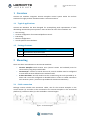
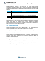
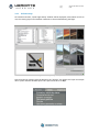
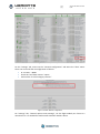
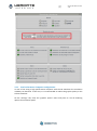
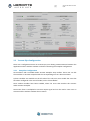
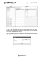
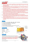
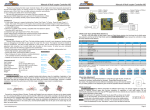
cod: pag: User Manual Veronte HIL-UM-v1.0.docx 1/10 cod: pag: Veronte HIL-UM-v1.0.docx 2/10 Version Version 1.0 Description Veronte HIL User Manual Date 15-07-2014 Table of Contents 1 2 OVERVIEW ................................................................................................................................. 3 1.1 TYPICAL APPLICATIONS .................................................................................................................. 3 1.2 PACKAGE CONTENT: ..................................................................................................................... 3 MOUNTING................................................................................................................................ 3 2.1 CABLE CONNECTION ..................................................................................................................... 3 2.2 X-PLANE CONFIGURATION ............................................................................................................. 4 2.2.1 Aircraft Model Installation .................................................................................................. 4 2.2.2 X-Plane setup ...................................................................................................................... 5 2.2.3 Low Performance Computer configuration ......................................................................... 7 2.3 3 VERONTE PIPE CONFIGURATION...................................................................................................... 8 2.3.1 Autopilot Configuration ...................................................................................................... 8 2.3.2 Veronte Pipe Communications............................................................................................ 9 OPERATION ............................................................................................................................. 10 Figures and Tables FIGURE 1: CONNECTION DIAGRAM ................................................................................................................... 3 FIGURE 2: X-PLANE: QUICK FLIGHT SETUP ......................................................................................................... 5 FIGURE 3: X-PLANE: SETUP ............................................................................................................................. 5 FIGURE 4: X-PLANE: INPUT AND OUTPUT DATA ................................................................................................... 6 FIGURE 5: X-PLANE: NETWORK CONFIGURATION................................................................................................. 6 FIGURE 6: X-PLANE: GENERAL OPTIONS AND WARNINGS....................................................................................... 7 FIGURE 7: X-PLANE: GRAPHICS OPTION ............................................................................................................. 8 FIGURE 8: VERONTE PIPE: HIL SETUP................................................................................................................ 9 FIGURE 9: VERONTE PIPE: HIL COMMUNICATIONS .............................................................................................. 9 cod: pag: Veronte HIL-UM-v1.0.docx 3/10 1 Overview Veronte HIL simulator integrates Veronte Autopilot control system within the X-Plane simulator for highly realistic simulation within a safe environment. 1.1 Typical applications Veronte HIL Simulator has been designed for accomplishing with requirements of most demanding unmanned system operators. Some of the main uses of the simulator are: Pilot training. Veronte configuration for unmanned platform control. PID setting. Mission configuration. Aircraft performance validation. 1.2 Package Content: Units Item 1 HIL Simulator connection cable 1 Software license for Veronte integration within the X-Plane simulator 2 Mounting There are three main elements in Veronte HIL Simulator: Veronte Autopilot: Both Veronte units (control station and onboard) must be connected by using the provided cable. Veronte Pipe: Permits to control the aircraft, control variables must be configured to mate with the ones defined on the X-Plane model. X-Plane Simulator: Aircraft model must be created using the tools provided by XPlane and it must be configured as detailed below in order to enable connection with Veronte system. (License not provided with Veronte HIL Simulator) 2.1 Cable connection Package content includes two connection cables, one for the Veronte Autopilot in the control station (1) and other to be connected to the Veronte Autopilot in the unmanned platform (2). Extension cable (3) is also available in custom lenghts. Figure 1: Connection Diagram cod: pag: Veronte HIL-UM-v1.0.docx 4/10 Provided cable is an extension to the regular cable used on the standard aircraft configuration. It permits to continue using all devices connected to the aircraft besides of the adding simulation features. The following connections must be performed to use the HIL simulator. Connector Connection A To Veronte Autopilot in the control station B To Veronte Autopilot aerial connector in the control station D To Veronte Autopilot aerial connector in the on the unmanned platform E To Veronte Autopilot in the aerial platform C&F C & F connectors must be joined together; an extension cable can be used. Table 1: Connection Diagram Cables connected to B and D connectors can include all devices connected in the platform and the control station. They will work normally as before connecting the simulator. Simulator can be also used by itself without connecting Veronte Autopilot to the platform; it is just needed to connect power to B & D connectors. 2.2 X-Plane Configuration X-Plane communications settings must be edited in order to have communication with Veronte system. Follow the next steps in order to make a proper configuration. For low performance computers, it may be needed to reduce the graphics quality on the simulator, as described below. 2.2.1 Aircraft Model Installation X-Plane simulator is compatible with a wide variety of platforms: airplane, helicopter, multicopter, surface vehicle.... In order to create the platform model, “Plane Maker” tool provided by X-Plane must be used. Once the aircraft model has been created, it can be integrated in the X-Plane simulator by following next steps: Copy the model folder to the “Aircraft” folder within the X-Plane installation directory. Copy the content on the “Airfoils” folder, available on the aircraft model folder, to the “Airfoils” directory within the X-Plane installation directory. cod: pag: 2.2.2 Veronte HIL-UM-v1.0.docx 5/10 X-Plane setup On X-Plane execution, “Quick Flight Setup” window will be displayed; select which aircraft to use, the starting airport and weather conditions to be simulated during the flight. Figure 2: X-Plane: Quick Flight Setup Data transmission settings must be edited on the “settings” tab. Select the “input and output data” option and edit the UDP speed. This speed must be set to 30/s. Figure 3: X-Plane: Setup cod: pag: Veronte HIL-UM-v1.0.docx 6/10 Figure 4: X-Plane: input and output data On the “settings” tab, enter into the “network configuration” and select the “data” menu. There user must edit the IP configuration as follows: IP: 127.0.0.1 49005 Check the “IP of data receiver” option Uncheck the “IP of Flir Imagery receiver” Figure 5: X-Plane: Network configuration On “settings” tab, “General options and warnings”, set the flight models per frame to a minimum of 3. It is needed for small aircraft simulation within X-Plane. cod: pag: Veronte HIL-UM-v1.0.docx 7/10 Figure 6: X-Plane: General options and warnings 2.2.3 Low Performance Computer configuration In case of not using a high performance computer with the HIL Simulator the simulation reliability can decrease. In this case, it is recommended to reduce the graphic quality on the X-Plane simulator. On the “settings” tab, enter the “graphics option” menu and press on “set all rendering options for maximum speed” cod: pag: Veronte HIL-UM-v1.0.docx 8/10 Figure 7: X-Plane: Graphics option 2.3 Veronte Pipe Configuration There are 2 configuration items on Veronte Pipe, one relating communications between the application and the X-Plane simulator and other refereeing the autopilot configuration. 2.3.1 Autopilot Configuration HIL simulation tab is available within Veronte Autopilot setup toolbar. There user can link the variables on Veronte Autopilot with the corresponding ones in X-Plane simulator. X-plane variables are available on the left side of the tab; user must enable the ones that have been configured in the aircraft model, on the “Plane Maker”. Once X-Plane variables have been enabled, select the servo that matches this actuator within Veronte autopilot. Conversion factor is multiplied to Veronte output signal and can be used in case units on Veronte and the X-Plane simulator do not match. cod: pag: Veronte HIL-UM-v1.0.docx 9/10 Figure 8: Veronte Pipe: HIL Setup 2.3.2 Veronte Pipe Communications In order to start the simulation, press on the HIL button, available on the setup toolbar. Popup screen will be displayed for selecting which aircraft, from the ones connected to the ground station, will be used for the simulation. Select the communications frequency, 20 Hz must be used as default, changing this value is only recommended for advanced users. Pres start in order to start the data transfer between X-Plane and Veronte Autopilot. Figure 9: Veronte Pipe: HIL Communications cod: pag: Veronte HIL-UM-v1.0.docx 10/10 3 Operation Once hardware has been connected and Veronte Pipe and X-Plane have been configured, user can operate the system as if on real flight. X-Plane flight starts on an airport; user must define a custom airport for simulating out of available airports. Once the aircraft has taken off from the airport on X-Plane the automatic control will start and the aircraft will fly to the defined mission on Veronte Pipe. Operator can fly the system as on real flight, being compatible with main Veronte features: real time mission edit, in-flight automatic to manual control, flight data recording... When using the HIL simulator connected to the platform. Control actuators will move as if it were flying. In order to avoid damaging the system or personnel, make sure that the motor is disconnected and there is no shock risk due to the actuators movement. Caution!! Always make sure that motor has been disconnected before starting a simulation. Otherwise the motor will run as if it were flying.