1
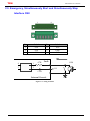
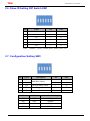
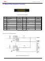
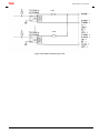
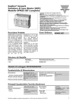
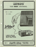
TPM 106-M304T User Manual Motionnet 106-M304T User Manual Version: V1.1 2015M02 To properly use the product, read this manual thoroughly is necessary. Part No.: 81-02114GH-010 1 TPM 106-M304T User Manual Revision History Date Revision Description 2014/5/5 1.0 Document creation. 2014/3/2 1.1 Add MPG interface description. 2 TPM 106-M304T User Manual © Copyright 2010 TPM The product, including the product itself, the accessories, the software, the manual and the software description in it, without the permission of TPM Inc. (“TPM”), is not allowed to be reproduced, transmitted, transcribed, stored in a retrieval system, or translated into any language in any form or by any means, except the documentation kept by the purchaser for backup purposes. The names of products and corporations appearing in this manual may or may not be registered trademarks, and may or may not have copyrights of their respective companies. These names should be used only for identification or explanation, and to the owners’ benefit, should not be infringed without any intention. The product’s name and version number are both printed on the product itself. Released manual visions for each product design are represented by the digit before and after the period of the manual vision number. Manual updates are represented by the third digit in the manual vision number. Trademark MS-DOS and Windows 95/98/NT/2000/XP, Visual Studio, Visual C++, Visual BASIC are registered trademarks of Microsoft. BCB (Borland C++ Builder) is registered trademark of Borland. Other product names mentioned herein are used for identification purposes only and may be trademarks and/or registered trademarks of their respective companies. 3 TPM 106-M304T User Manual Electrical safely To prevent electrical shock hazard, disconnect the power cable from the electrical outlet before relocating the system. When adding or removing devices to or from the system, ensure that the power cables for the devices are unplugged before the signal cables are connected. Disconnect all power cables from the existing system before you add a device. Before connecting or removing signal cables from motherboard, ensure that all power cables are unplugged. Seek professional assistance before using an adapter or extension card. These devices could interrupt the grounding circuit. Make sure that your power supply is set to the voltage available in your area. If the power supply is broken, contact a qualified service technician or your retailer. Operational safely Please carefully read all the manuals that came with the package, before installing the new device. Before use ensure all cables are correctly connected and the power cables are not damaged. If you detect and damage, contact the dealer immediately. To avoid short circuits, keep paper clips, screws, and staples away from connectors, slots, sockets and circuitry. Avoid dust, humidity, and temperature extremes. Do not place the product in any area where it may become wet. If you encounter technical problems with the product, contact a qualified service technician or the dealer. 4 TPM 106-M304T User Manual Contents CONTENTS .................................................................................................................................................................................. 5 1. 106-M304T INTRODUCTION.................................................................................................................................................... 6 1.1. FEATURES.................................................................................................................................................................................... 6 1.2. HARDWARE LAYOUT ...................................................................................................................................................................... 7 2. I/O INTERFACE DESCRIPTION .................................................................................................................................................. 9 2.1. COMMUNICATION CONNECTOR RJ-45 CN1/CN2 .............................................................................................................................. 9 2.2. POWER CONNECTOR – CN3 ........................................................................................................................................................... 9 2.3. DRIVE’S IO INTERFACE CONNECTOR CN4/CN5/CN6/CN7 ............................................................................................................... 10 2.4. MACHINERY I/O SIGNALS CN9/CN10 ........................................................................................................................................... 14 2.5. EMERGENCY, SIMULTANEOUSLY START AND SIMULTANEOUSLY STOP INTERFACE CN8 ................................................................................ 16 2.6. SLAVE ID SETTING DIP SWITCH SW1 ............................................................................................................................................. 17 2.7. CONFIGURATION SETTING SW2 .................................................................................................................................................... 17 2.8. MANUAL PULSE GENERATOR CONNECTOR ....................................................................................................................................... 18 3. INTRODUCTION OF THE TERMINAL BOARD FOR 106-M304T ................................................................................................ 20 3.1. 104-304T................................................................................................................................................................................ 20 5 TPM 106-M304T User Manual 1. 106-M304T Introduction 1.1. Features Max. 6.5MHz, 4-Axis pulse output Linear, circular and continuous interpolation High speed position latch function Simultaneously start/stop on multiple axes Programmable acceleration and deceleration time Programmable pulse output and interrupt Position compare and trigger outputSpecifications 4-Axis Motion Control Pulse output mode: ±OUT/DIR, ±CW/CCW Pulse output rate: Max. 6.5Mpps / Min. 0.05pps Position range: 32 bits(±2,147,483,648 pulses) Home return mode: 13 types Velocity profiles: T-curve, S-curve Interpolation mode: linear, circular, helix and continuous Counter for encoder feedback signals: 32 bits up/down x 4 Position latch input: LTC x 4 Position compare output: CMP x4, with programmable pulse width Compare trigger output rate: Max. 250Kbps FIFO buffer for compare trigger positions: 2 axes 250 (default), 500, 1000, 2000 points for each axis, optional. Incremental encoder input: ±EA x 4, ±EB x 4 Encoder index signal input: ±EZ x 4 Machine interface: PEL x 4, MEL x 4, ORG x 4, SLD x 4 Servo driver interface: ALM x 4, RDY x 4, SVON x 4, INP x 4, ERC x 4 6 TPM 106-M304T User Manual 1.2. Hardware Layout 7 TPM 106-M304T User Manual Name Description CN1 RJ45 Communication Control Connector CN2 RJ45 Communication Control Connector CN3 Power Connector CN4 Axis0 Drive’s IO Interface Connector CN5 Axis1 Drive’s IO Interface Connector CN6 Axis2 Drive’s IO Interface Connector CN7 Axis3 Drive’s IO Interface Connector CN8 Emergency, Simultaneously Start and Simultaneously Stop Interface CN9 Axis0 & Axis1 Machinery I/O Signals Connector CN10 Axis2 & Axis3 Machinery I/O Signals Connector SW1 Device Address Setting SW2 Baud rate , Terminal Resistor and so on Setting RUN LED1 Green in LED:In normal communication ERR Red Led in LED1:error communication PG1 Yellow Led in LED1:DC +3.3V In Normal Level PG2 Yellow Led in LED1:DC +3.3V Supply SLD Red Led in LED2&LED3:Indicate SLD Input Signal ORG Green Led In LED2&LED3:Indicate ORG Input signal PEL Yellow Led In LED2&LED3:Indicate PEL Input Signal MEL Yellow Led In LED2&LED3:Indicate MEL Input Signal 8 TPM 106-M304T User Manual 2. I/O Interface Description 2.1. Communication connector RJ-45 CN1/CN2 8 Pin Label 1 NC 2 NC 3 RS485+ 4 NC Function 1 Pin Label Function Reserved 5 NC Reserved 6 RS485- RS485 Differential Signal (+) 7 NC Reserved Reserved 8 NC Reserved Reserved RS485 Differential Signal (-) 2.2. Power Connector – CN3 1 Pin Label 1 FG 2 GND Ground ( DC +24V) 3 24V +24V Power 3 Function Field Ground 9 TPM 106-M304T User Manual 2.3. Drive’s IO Interface Connector CN4/CN5/CN6/CN7 9 1 26 Pin Label 1 SVON 2 Function 19 Pin Label Function Servo on output signal 14 BRK- Braking signal(-) INP In-position input signal 15 EGND I/O power ground 3 ERC Deviation counter clear output signal 16 EB- Encoder B-phase (-) 4 RDY Ready input signal 17 EB+ Encoder B-phase (+) 5 OUT- Pulse signal (-) 18 EGND I/O power ground 6 OUT+ Pulse signal (+) 19 EMG Emergency stop output signal 7 EA- Encoder A-phase (-) 20 EGND I/O power ground 8 EA+ Encoder A-phase (+) 21 EGND I/O power ground 9 BRK+ Braking signal(+) 22 EGND I/O power ground 10 RST Alarm reset output signal 23 DIR- Direction signal (-) 11 ALM Alarm input signal 24 DIR+ Direction signal (+) 12 E24V I/O power supply, +24V 25 EZ- Encoder Z-phase (-) 13 EGND I/O power ground 26 EZ+ Encoder Z-phase (+) 10 TPM 106-M304T User Manual ALM (Servo Alarm / Digital Input Signal) ALM- input signal from ALM signal at servo driver. Servo driver will issue ALM output when it is under abnormal operation or over-loading. INP (Axis In Position Signal / Digital Input Signal) INP is an input signal at 106-M304T and is used to read the INP status inside servo driver. RDY (Driver Ready Signal / Digital Input Signal) RDY is an input signal and is used to read the RDY signal at servo driver. 5mA 4 1 3 2 NPN 5V 1K Internal Curcuit GND Figure 2-1: Wiring for NPN sink mode SVON(Servo On / Digital Output Signal) SVON is an output signal from PCI-M114-GL and is used to make driver servo-on to hold the motor. RALM(Servo Alarm Reset / Digital Output Signal) This RALM signal is designed to reset ALM status inside servo driver if the alarm status is able to be reset. ERC (Deviation Counter Clear / Digital Output Signal) ERC output will be active when the following condition is activated. Homing is completed. PEL/MEL is active. ALM is active. User issues EMG by software. 5mA 24V 1 4 2 3 4.7K 1 4 2 3 GND Internal Curcuit Figure 2-2: output wiring diagram 11 TPM 106-M304T User Manual OUT and DIR (Pulse Output Control / Digital Output Signal) There are 6 types of pulse output of 106-M304T. User has to specify the electrical spec. as differential or open collector first. Then select DIR/OUT or CW/CCW. 20mA 2 OUT+ 2 3 OUT- 1 3 1 AM26LS32 AM26C31 Internal Curcuit Differential line driver output 20mA 2 OUT+ 1 3 3 4 100 5 OUT- 1 6 100 AM26C31 Internal Curcuit Optocoupler wiring 20mA 2 OUT+ 3 OUT- TTL 1 AM26C31 200 GND GND Internal Curcuit TTL Receive pattern wiring Figure 2-3: OUT and DIR output 12 TPM 106-M304T User Manual EA, EB and EZ (Encoder A, B and Z Phase) 20mA 6 1 EA+ 2 100 5 1 3 4 3 EA- AM26C31 100 Internal Curcuit Differential line driver encoder input Pulse 10mA 6 1 100 5 4 EA+ 3 EA- GND 100 Internal Curcuit Pulse input Figure 2-4: EA , EB and EZ intput 13 TPM 106-M304T User Manual 2.4. Machinery I/O Signals CN9/CN10 2 20 1 19 CN9 Pin Label Pin Label 1 ELX+ 2 ELX- 3 ORGX 4 SLDX 5 COM 6 CMPX 7 LTCX 8 EGND 9 BRKX+ 10 BRKX- 11 ELY+ 12 ELY- 13 ORGY 14 SLDY 15 COM 16 CMPY 17 LTCY 18 EGND 19 BRKY+ 20 BRKY- CN10 Pin Label Pin Label 1 ELZ+ 2 ELZ- 3 ORGZ 4 SLDZ 5 COM 6 CMPZ 7 LTCZ 8 EGND 9 BRKZ+ 10 BRKU- 11 ELU+ 12 ELU- 13 ORGU 14 SLDU 15 COM 16 CMPU 17 LTCU 18 EGND 19 BRKU+ 20 BRKU- 14 TPM 106-M304T User Manual PEL and MEL (End Limit / Digital Input Signal) There are two end-limit signals called PEL and MEL for each axis. Usually they are Normal-Close type signals from external sensors. PEL indicates the limit of motion in the plus direction and MEL indicates the limit of motion in the minus direction. ORG (Origin / Digital Input Signal) The origin signals (ORG1~ORG4) are necessary when the position feedback is incremental type or without any feedback encoders. They are used to indicate the origin of the system. SLD (Slow Down / Input Signal) The SLD signals are used to help the axis decelerate to stop by hardware. LTC (Counter Latch) LTC is used to latch the value in the counter when the LTC input is active. 4 1 3 2 4.7K 5mA NPN 24V COM Internal Curcuit GND Figure 2-5: wiring for NPN sink mode CMP (Position Compare / Output Signal) CMP signals are used to make a comparison between target value and actual value and generate a trigger signal output. 5V 1 3 5mA 6 1K 5 CMP 4 5V LED GND Internal Curcuit 1K TTL GPIO CMP output signal circuit Figure 2-6: output wiring diagram 15 TPM 106-M304T User Manual 2.5. Emergency, Simultaneously Start and Simultaneously Stop Interface CN8 1 6 Pin Label Pin Label 1 STA 4 STP 2 STA 5 EMG 3 STP 6 GND 4 1 3 2 4.7K 5mA NPN 24V COM Internal Curcuit GND Figure 2-7: wiring for EMG 16 TPM 106-M304T User Manual 2.6. Slave ID Setting DIP Switch SW1 Pin Label ON OFF 1 A5 1 0 2 A4 1 0 3 A3 1 0 4 A2 1 0 5 A1 1 0 6 A0 1 0 Note: Address = 32xA5+16xA4+8xA3+4xA2+2xA1+A0 2.7. Configuration Setting SW2 Pin Label 1 B1 2 B0 3 TD 4 5 Description ON OFF 1 0 1 0 Time-Out Status Latch 1 0 TM Watch Dog Mode 1 0 TR Terminate Resistance Enable Disable Baud-Rate Setting B0 B1 Baud-Rate Setting OFF OFF 20Mbps ON OFF 10Mbps OFF ON 5Mbps ON ON 2.5Mbps 17 TPM 106-M304T User Manual 2.8. Manual Pulse Generator Connector 2 20 1 19 Figure 2-8: MPG pin definition Pin 1 3 5 7 9 11 13 15 17 19 Label +24V/200mA X Select Z Select X1 X100 +5V/200mA PA IOCOM JOG+ Reserved Description Power Input signal Input signal Input signal Input signal Power Input signal Input signal Pin 2 4 6 8 10 12 14 16 18 20 Label G24 Y Select U Select X10 IOCOM DGND PB Enable JOGReserved Description Ground Input signal Input signal Input signal Ground Input signal Input signal Input signal Table 2-1: MPG pin definition The logic circuit is illustrated below. 4.7K 4.7K Figure 2-9: hand wheel NPN logic circuit 18 TPM 106-M304T User Manual 4.7K 4.7K Figure 2-10: hand wheel PNP logic circuit 19 TPM 106-M304T User Manual 3. Introduction of the Terminal Board for 106-M304T 3.1. 104-T304 74mm 63.5mm Name Description CN1 Power Connector CN2 See Details below CN3 See Details below CN4 See Details below CN5 See Details below CN7 Axis0 & Axis1 / Axis2 & Axis3 Machinery I/O Signals Connector 20 TPM 106-M304T User Manual 1 3 CN1 Pin Label Function 1 FG 2 GND Ground ( DC +24V) 3 24V +24V Power Field Ground 21 TPM 106-M304T User Manual CN2/CN3/CN4/CN5 10 1 CN2 Pin Label Pin Label 1 +24V 7 +24V 2 ELX+ 8 ORGX 3 EGND 9 EGND 4 +24V 10 BRKX+ 5 ELX- 6 EGND CN3 1 +24V 7 +24V 2 SLDX 8 LTCX 3 EGND 9 EGND 4 +24V 10 BRKX- 5 CMPX 6 EGND CN4 1 +24V 7 +24V 2 ELY+ 8 ORGY 3 EGND 9 EGND 4 +24V 10 BRKY+ 5 ELY- 6 EGND CN5 1 +24V 7 +24V 2 SLDY 8 LTCY 3 EGND 9 EGND 4 +24V 10 BRKY- 5 CMPY 6 EGND 22