1
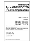
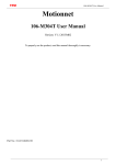
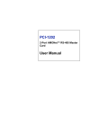
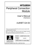
Channel Isolated
Pulse Input Module
User’s Manual
(Hardware)
QD60P8-G
Thank you for buying the Mitsubishi general-purpose programmable
controller MELSEC-Q Series
Prior to use, please read both this manual and detailed manual
thoroughly and familiarize yourself with the product.
MODEL QD60P8-G-U-H-JE
MODEL
13JT94
CODE
IB(NA)-0800229-C(0709)MEE
©2002 MITSUBISHI ELECTRIC CORPORATION
z SAFETY PRECAUTIONS z
(Read these precautions before using.)
When using Mitsubishi equipment, thoroughly read this manual and the
associated manuals introduced in this manual. Also pay careful attention to
safety and handle the module properly.
These precautions apply only to Mitsubishi equipment. Refer to CPU module
User's Manual for a description of the programmable controller system safety
precautions.
These z SAFETY PRECAUTIONS z classify the safety precautions into two
categories: "DANGER" and "CAUTION".
DANGER
Procedures which may lead to a dangerous condition and
cause death or serious injury, if not carried out properly.
Procedures which may lead to a dangerous condition and
CAUTION cause superficial to medium injury, or physical damage
only, if not carried out properly.
Depending on circumstances, procedures indicated by
CAUTION may also
be linked to serious results.
In any case, it is important to follow the directions for usage.
Store this manual in a safe place so that you can take it out and read it whenever
necessary. Always forward it to the end user.
A-1
[INSTALLATION PRECAUTION]
CAUTION
z Use the programmable controller in an environment that meets the general specifications
contained in CPU module User's Manual to use.
Using this programmable controller in an environment outside the range of the general
specifications may cause electric shock, fire, malfunction, and damage to or deterioration
of the product.
z When installing the module, securely insert the module fixing tabs into the mounting holes
of the base unit while pressing the installation lever located at the bottom of the module
downward. Improper installation may result in malfunction, breakdown or the module
coming loose and dropping.
Securely fix the module with screws if it is subject to vibration or shock during use.
Tighten the screws within the range of specified torque.
If the screws are loose, it may cause the module to fallout short circuits or malfunction.
If the screws are tightened too much, it may cause damage to the screw and/or the
module, resulting in fallout short circuits or malfunction.
z Switch all phases of the external power supply off when mounting or removing the
module. Not doing so may cause damage to the module.
z Do not install/remove the module to/from the base unit, or the terminal block to/from the
module more than 50 times after the first use of the product. (IEC 61131-2compliant)
Failure to do so may cause malfunction.
z Do not directly touch the conductive area or electronic components of the module.
Doing so may cause malfunction or failure in the module.
[WIRING PRECAUTION]
DANGER
z Switch all phases of the external power supply off when installing or placing wiring.
Not doing so may cause electric shock or damage to the product.
z Be careful not to let foreign matter such as sawdust or wire chips get inside the module.
These may cause fires, failure or malfunction.
z The top surface of the module is covered with protective film to prevent foreign objects
such as cable offcuts from entering the module when wiring.
Do not remove this film until the wiring is complete.
Before operating the system, be sure to remove the film to provide adequate ventilation.
z The cables connected to the module should be placed in a duct or fixed.
Not doing so can cause the module or cables to be damaged when the cables swing,
more or are pulled carefully, for example or to malfunction due to poor cable connection.
CAUTION
z Check the layout of the terminals and then properly route the wires to the module.
Fire or failure may result if incorrect voltage is input or incorrect wiring is performed.
z When removing the cable from the module, do not pull the cable. When disconnecting a
cable without a terminal block, unscrew on the part that is connected to the module.
Pulling the cable that is still connected to the module may cause malfunction or damage to
the module or cable.
z Control wires and pulse input wires should not be routed near or bundled with the main
circuit cable, power cable and/or other such load-carrying cables other than those for the
programmable controller. These cables should be separated by at least 150 mm (5.9 in.).
They can cause electrical interference, surges and inductance that can lead to
mis-operation.
z Always ground the shielded cable for the programmable controller. There is a risk of
electric shock or malfunction.
A-2
Revisions
* The manual number is given on the bottom right of the top cover.
Print Date
*Manual Number
Revision
Apr., 2002 IB(NA)-0800229-A First edition
Sep., 2006 IB(NA)-0800229-B Partial Correction
Section 5.2
Sep., 2007 IB(NA)-0800229-C Partial Correction
SAFETY PRECAUTIONS, Chapter 2,
Section 3.1, Section 5.1, Section 5.2
This manual confers no industrial property rights or any rights of any other kind, nor does it
confer any patent licenses. Mitsubishi electric Corporation cannot be held responsible for
any problems involving industrial property rights which may occur as a result of using the
contents noted in this manual.
© 2002 MITSUBISHI ELECTRIC CORPORATION
A-3
CONTENTS
1. Overview ........................................................................................................1
2. Performance Specifications ...........................................................................1
3. Handling.........................................................................................................3
3.1 Handling Precautions................................................................................3
4. Part Identification Nomenclature ....................................................................4
5. Wiring.............................................................................................................5
5.1 Wiring Precautions ...................................................................................5
5.2 External Wiring .........................................................................................7
5.3 External Interface .....................................................................................8
6. Setting from GX Developer ............................................................................9
7. External Dimensions ....................................................................................10
About Manuals
The following manuals are related to this product.
Referring to this list, please request the necessary manuals.
Detailed Manual
Manual name
Channel Isolated Pulse Input Module User’s Manual
Manual No.
(Model code)
SH-080313E
(13JR54)
Conformation to the EMC Directive and Low Voltage Instruction
For details on making Mitsubishi programmable controller conform to the EMC
directive and low voltage instruction when installing it in your product, please
refer to Chapter 3, "EMC Directive and Low Voltage Instruction" of the using
programmable controller CPU module User's Manual(Hardware).
The CE logo is printed on the rating plate on the main body of the
programmable controller that conforms to the EMC directive and low voltage
instruction.
To make this product conform to the EMC directive and low voltage instruction,
please refer to Chapter 5 "Wiring".
A-4
1. Overview
This manual explains how to handle the Channel Isolated Pulse Input Module
(QD60P8-G).
2. Performance Specifications
The following describes the performance specifications of the QD60P8-G.
Model name
QD60P8-G
Item
Counting speed
30kpps 10kpps 1kpps 100pps 50pps
10pps
1pps
0.1pps
switch settings
Number of I/O
32 points (I/O assignment: 32 points for intelligent function module)
occupied points
Number of channels
8 channels
Count
Phase
1-phase input
input
Signal level
5VDC/12 to 24VDC
signal
Input derating
Refer to the derating chart (Next page)
Counting
speed
30kpps 10kpps 1kpps 100pps 50pps
10pps
1pps
0.1pps
(Max)*
Sampling pulse number
: 16-bit binary (0 to 32767)
Counting
Accumulating count value
: 32-bit binary (0 to 99999999)
range
Input pulse value
: 32-bit binary (0 to 2147483647)
Counter
Count type
Linear counter method, Ring counter method
Minimum
count pulse
width (Duty
ratio 50%)
33.4 s
100 s
1ms
10ms
20ms
100ms
1s
10s
16.7 16.7
s s
50 50
s s
0.5 0.5
ms ms
5 5
ms ms
10 10
ms ms
50 50
ms ms
0.5 0.5
s s
5s 5s
For 1 min at 1500 VAC between AC external connecting terminals and general
grounding
Dielectric withstand
For 1 min at 500 VAC between DC external connecting terminals and general
voltage
grounding
For 1 min at 1780 VAC between channels
5 M or more at 500 VDC between AC external connecting terminals and
Insulation resistance
general grounding
Connected terminal
18 points terminal block
2
Applicable wire size
0.3 to 0.75mm
Applicable solderless
R1.25-3 (A solderless terminals with sleeves cannot be used)
terminals
Internal current
0.58A
comsumption (5VDC)
Weight
0.17kg
External dimensions
27.4 (1.08) (W) 98 (3.86) (H) 90 (3.54) (D) [mm (in.)]
* Counting speed is affected by pulse rise and fall time. Possible counting speeds are shown in the
following chart. Note that if a pulse that has a large rise and/or fall time is counted, a miscount may
occur.
1
Rise/fall time
t = 8.4 s or less
t = 25 s or less
t = 250 s or less
t = 2.5ms or less
t = 5ms or less
t = 25ms or less
t = 250ms or less
t = 2.5s or less
t = 5s
30kpps
30kpps
10kpps
-
Counting speed switch settings
1kpps 100pps 50pps
10pps
1kpps 100pps 50pps
10pps
1kpps 100pps 50pps
10pps
1kpps 100pps 50pps
10pps
100pps 100pps 50pps
10pps
50pps
50pps
10pps
10pps
10pps
1pps
-
10kpps
10kpps
10kpps
1kpps
-
t
1pps
1pps
1pps
1pps
1pps
1pps
1pps
1pps
0.1pps
-
0.1pps
0.1pps
0.1pps
0.1pps
0.1pps
0.1pps
0.1pps
0.1pps
0.1pps
0.05pps
t
<Derating Chart>
(%)
100
90
* 80
ON
ratio 70
60
50
40
0
30VDC
10
20 30 40 50 55 ( C)
Ambient temparature
* "ON" indicates the status where voltage is applied to pulse input
terminals.
For the general specifications of the QD60P8-G, see User’s Manual for the CPU module used.
2
3. Handling
3.1 Handling Precautions
(1) Since the module case is made of resin, do not drop it or subject it to strong
impact.
(2) The module can easily be secured to the base unit using the hooks located
at the top of the module. However, if the module is to be placed in an area
that is subject to strong vibration or impact, we recommend that it is
secured with module fixing screws (to be provided by the user). In this case,
tighten the module fixing screws within the following torque range.
If the screw is too loose, it may cause a drop, short circuit, or malfunction.
Excessive tightening may damage the screw and/or the module, resulting
in a drop, short circuit or malfunction.
Screw location
Tightening torque range
Module fixing screw (M3 screw)
0.36 to 0.48N•m
Terminal block terminal screw (M3 screw)
0.42 to 0.58N•m
Terminal block fixing screw (M3.5 screw)
0.66 to 0.89N•m
*1 The module can be easily fixed onto the base unit using the hook at the top
of the module.
However, it is recommended to secure the module with the module fixing
screw if the module is subject to significant vibration or shock.
3
4. Part Identification Nomenclature
(1) Part identification nomenclature
QD60P8-G
1)
RUN
2)
ERR.
CH1
CH2
CH3
CH4
V+
C
H
V1
CH5
CH6
CH7
CH8
3)
1
2
V+
C
H
V2
3
4
V+
C
H
V3
5
V+
C
H
V4
7
V+
C
H
V5
9
6
8
10
V+
C
H
V6
11
V+
C
H
V7
13
V+
C
H
V8
15
12
14
16
17
(FG)
18
5/1224VDC
Number
Name
1)
RUN LED
2)
ERR.LED
3)
CH1 to CH8
LED
Description
Indicates the operating status of the QD60P8-G.
On : Operating normally
Off : 5V power is off, watch dog timer error occurred,
in the module changeable status during online module
change
Indicates the error status of the QD60P8-G.
On : Error is occurring.
Off : Operating normally
Displays the voltage application status of the input terminals.
On : Voltage is being applied to the CH1 to CH8 pulse input
terminal.
Off : No voltage applied to pulse input terminals of CH1 to CH8.
4
5. Wiring
DANGER
z Switch all phases of the external power supply off when installing or placing wiring.
Not doing so may cause electric shock or damage to the product.
z Check the layout of the terminals and then properly route the wires to the module.
Fire or failure may result if incorrect voltage is input or incorrect wiring is performed.
z Do not apply the voltage exceeding the value set on the “Intelligent function module
switch setting” dialog box to the terminals.
Failure to observe this may cause fire or failure.
5.1 Wiring Precautions
(1) Use separate cables with the AC control circuit and QD60P8-G’s external
input signals to avoid the influence of AC side surges and induction.
(2) Do not run the cable close to , or bundle them with, the main circuit and
high-voltage cables and the load cables from other than the programmable
controller.
Failure to do so will make the cables susceptible to noise, surges and
induction.
(3) If there may be the effect of noise when a cable to be connected to the
QD60P8-G and the power line are installed close to each other, use a
general shielded twisted pair cable as a countermeasure against noise.
The shield must be grounded on the QD60P8-G side.
(4) The shielded twisted pair cable for connecting QD60P8-G can be secured
in place.
If the shielded cable is not secured, unevenness or movement of the
shielded twisted pair cable or careless pulling on it could result in damage
to the QD60P8-G or shielded cable or defective cable connections could
cause mis-operation of the QD60P8-G.
(5) No solderless terminals with insulation sleeves can be used on the terminal
block.
It is recommended to cover the electric wire connecting section of each
solderless terminal with a marking tube or insulating tube.
(6) The cables connected to the QD60P8-G should be placed in a duct or fixed,
Not doing so can cause the QD60P8-G or cables to be damaged when the
cables swing, move or are pulled carelessly, for example, or to malfunction
due to poor cable connection.
(7) To comply with the EMC Directive and Low-Voltage Directive, always
ground the QD60P8-G to the control box using shielded twisted pair cables
twisted pair cables and AD75CK cable clamping (Mitsubishi Electric make).
5
Inside control box
QD60P8-G
20cm(7.88inch)
to 30cm(11.82inch)
AD75CK
6
5.2 External Wiring
(1) Wiring example with a source logic type encoder (24VDC)
(a) For transistor output
QD60P8-G
Encoder
Shielded
twisted pair cable
CH1 V+
+24V
OUT
CH1 VFG
24VDC
power supply
+
-
(b) For contact output
QD60P8-G
Encoder
Shielded
twisted pair cable
CH1 V+
+24V
OUT
CH1 VFG
24VDC
power supply
+
-
(2) Wiring example with a sink logic type encoder (24VDC)
(a) For transistor output
QD60P8-G
Encoder
Shielded
twisted pair cable
GND
CH1 V+
CH1 VFG
24VDC
power supply
OUT
OUT
+
-
7
(b) For contact output
QD60P8-G
Encoder
Shielded
twisted pair cable
OUT
OUT
GND
CH1 V+
CH1 VFG
24VDC
power supply
+
-
5.3 External Interface
Shows summary image of the internal circuit of the interface for connection to
external devices of the QD60P8-G.
Input/
output
class
Internal circuit
1,3,5,
7,9,11,
13,15
Input
2,4,6
8,10,12
14,16
-
-
Input
Operating
voltage
current
Operation
(guaranteed (guaranteed
value)
value)
4mA or
5VDC* 3.5 to 5.5V
When
more
CH1 to 8 V+
ON
12 to
4mA or
10.2 to 30V
24VDC*
more
0.5mA or
5VDC* 1.0V or less
When
less
CH1 to 8 VOFF
12 to
0.5mA or
2.0V or less
24VDC*
less
FG
-
Terminal
Signal name
No.
17,18
* The input voltage range is selected from "5VDC" or "12 to 24VDC" by using intelligent
function module switch.
Terminal number
Signal name
1
CH1 V+
CH1
2
CH1 V3
CH2 V+
CH2
4
CH2 V5
CH3 V+
CH3
6
CH3 V7
CH4 V+
CH4
8
CH4 V9
CH5 V+
CH5
10
CH5 V11
CH6 V+
CH6
12
CH6 V13
CH7 V+
CH7
14
CH7 V15
CH8 V+
CH8
16
CH8 V-
8
6. Setting from GX Developer
Settings for QD60P8-G input voltage selection, pulse edge selection, linear
counter or ring counter selection, and input filter setting can be made by the GX
Developer intelligent function module switch setting.
Use the GX Developer's I/O assignment setting to make the intelligent function
module switch setting.
y The intelligent function module switch has switches 1 to 5, and is set at 16 bit
data.
y If the intelligent function module switch setting is not operated, the default
setting for switches 1 to 5 is 0.
Switch No.
Setting items
Setting details /bit assignment
b15 b12
b8
b4
b0
Setting items
CH1 Input voltage
CH2 Input voltage
CH3 Input voltage
CH4 Input voltage
CH5 Input voltage
CH6 Input voltage
CH7 Input voltage
CH8 Input voltage
Not used
Switch 1
Input voltage
selection
b15 b12
b8
b4
Default value
Meaning
0:12 to 24
VDC
1:5VDC
0000H
b0
Setting items
CH1 Pulse edge
CH2 Pulse edge
CH3 Pulse edge
CH4 Pulse edge
CH5 Pulse edge
CH6 Pulse edge
CH7 Pulse edge
CH8 Pulse edge
Pulse edge
selection
Switch 2
Setting items
CH1 Linear/Ring counter
CH2 Linear/Ring counter
CH3 Linear/Ring counter
CH4 Linear/Ring counter
CH5 Linear/Ring counter
CH6 Linear/Ring counter
CH7 Linear/Ring counter
CH8 Linear/Ring counter
Linear
counter or
Ring counter
selection
9
Meaning
0:Rise
edge
1:Fall
edge
0000H
Meaning
0:Linear
counter
1:Ring
counter
Switch No.
Setting items
Setting details /bit assignment
H
Switch 3
Setting items
CH1 Input filter
Input filter
setting (CH1
to CH4)
CH2 Input filter
CH3 Input filter
CH4 Input filter
H
Switch 4
Input filter
setting (CH5
to CH8)
Setting items
CH5 Input filter
CH6 Input filter
CH7 Input filter
CH8 Input filter
Switch 5
Default value
Meaning
0:30kpps
1:10kpps
2:1kpps
3:100pps
4:50pps
5:10pps
6:1pps
7:0.1pps
0000H
Meaning
0:30kpps
1:10kpps
2:1kpps
3:100pps
4:50pps
5:10pps
6:1pps
7:0.1pps
0000H
Vacant
7. External Dimensions
QD60P8-G
RUN
98 (3.86)
ERR.
CH1
CH2
CH3
CH4
CH5
CH6
CH7
CH8
V+
C
H
V1
1
V+
C
H
V2
3
2
4
V+
C
H
V3
5
V+
C
H
V4
7
V+
C
H
V5
9
10
V+
C
H
V6
11
V+
C
H
V7
13
V+
C
H
V8
15
(FG)
6
8
12
14
16
17
18
5/1224VDC
90 (3.54)
27.4 (1.08)
Unit: mm (in.)
10
Warranty
Mitsubishi will not be held liable for damage caused by factors found not to be the cause of
Mitsubishi; machine damage or lost profits caused by faults in the Mitsubishi products;
damage, secondary damage, accident compensation caused by special factors
unpredictable by Mitsubishi; damages to products other than Mitsubishi products; and to
other duties.
For safe use
y This product has been manufactured as a general-purpose part for general industries, and
has not been designed or manufactured to be incorporated in a device or system used in
purposes related to human life.
y Before using the product for special purposes such as nuclear power, electric power,
aerospace, medicine or passenger movement vehicles, consult with Mitsubishi.
y This product has been manufactured under strict quality control. However, when installing
the product where major accidents or losses could occur if the product fails, install
appropriate backup or failsafe functions in the system.
Country/Region Sales office/Tel
Country/Region Sales office/Tel
U.S.A
Mitsubishi Electric Automation Inc.
Hong Kong
Mitsubishi Electric Automation
(Hong Kong) Ltd.
500 Corporate Woods Parkway Vernon
10th Floor, Manulife Tower, 169 Electric
Hills, IL 60061, U.S.A.
Road, North Point, Hong Kong
Tel : +1-847-478-2100
Tel : +852-2887-8870
Brazil
MELCO-TEC Rep. Com.e Assessoria
China
Mitsubishi
Electric Automation
Tecnica Ltda.
(Shanghai) Ltd.
Rua Correia Dias, 184,
4/F Zhi Fu Plazz, No.80 Xin Chang Road,
Edificio Paraiso Trade Center-8 andar
Shanghai 200003, China
Paraiso, Sao Paulo, SP Brazil
Tel : +86-21-6120-0808
Tel : +55-11-5908-8331
Taiwan
Setsuyo Enterprise Co., Ltd.
Germany
Mitsubishi Electric Europe B.V. German
6F No.105 Wu-Kung 3rd.Rd, Wu-Ku
Branch
Hsiang, Taipei Hsine, Taiwan
Gothaer Strasse 8 D-40880 Ratingen,
Tel : +886-2-2299-2499
GERMANY
Korea
Mitsubishi Electric Automation Korea
Co., Ltd.
Tel : +49-2102-486-0
1480-6, Gayang-dong, Gangseo-ku
U.K
Mitsubishi Electric Europe B.V. UK
Seoul 157-200, Korea
Branch
Tel : +82-2-3660-9552
Travellers Lane, Hatfield, Hertfordshire.,
Singapore
Mitsubishi Electric Asia Pte, Ltd.
AL10 8XB, U.K.
307 Alexandra Road #05-01/02,
Tel : +44-1707-276100
Mitsubishi Electric Building,
Italy
Mitsubishi Electric Europe B.V. Italian
Singapore 159943
Branch
Tel : +65-6470-2460
Centro Dir. Colleoni, Pal. Perseo-Ingr.2
Thailand
Mitsubishi Electric Automation (Thailand)
Via Paracelso 12, I-20041 Agrate Brianza.,
Co., Ltd.
Milano, Italy
Bang-Chan Industrial Estate No.111
Tel : +39-039-60531
Moo 4, Serithai Rd, T.Kannayao,
Spain
Mitsubishi Electric Europe B.V. Spanish
A.Kannayao, Bangkok 10230 Thailand
Branch
Tel : +66-2-517-1326
Indonesia
P.T. Autoteknindo Sumber Makmur
Carretera de Rubi 76-80,
Muara Karang Selatan, Block A/Utara
E-08190 Sant Cugat del Valles,
No.1 Kav. No.11 Kawasan Industri
Barcelona, Spain
Pergudangan Jakarta - Utara 14440,
Tel : +34-93-565-3131
P.O.Box 5045 Jakarta, 11050 Indonesia
France
Mitsubishi Electric Europe B.V. French
Tel : +62-21-6630833
Branch
India
Messung Systems Pvt, Ltd.
25, Boulevard des Bouvets, F-92741
Electronic Sadan NO:III Unit No15,
Nanterre Cedex, France
M.I.D.C Bhosari, Pune-411026, India
TEL: +33-1-5568-5568
Tel : +91-20-2712-3130
South Africa
Circuit Breaker Industries Ltd.
Australia
Mitsubishi Electric Australia Pty. Ltd.
Private Bag 2016, ZA-1600 Isando,
348 Victoria Road, Rydalmere,
South Africa
N.S.W 2116, Australia
Tel : +27-11-928-2000
Tel : +61-2-9684-7777
HEAD OFFICE : TOKYO BUILDING, 2-7-3 MARUNOUCHI, CHIYODA-KU, TOKYO 100-8310, JAPAN
NAGOYA WORKS : 1-14, YADA-MINAMI 5-CHOME, HIGASHI-KU, NAGOYA, JAPAN
When exported from Japan, this manual does not require application to the Ministry
of Economy, Trade and Industry for service transaction permission.
Specifications subject to change without notice.
Printed in Japan on recycled paper.