1
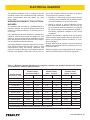
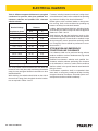
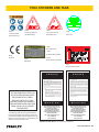
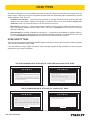
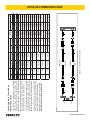
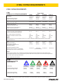
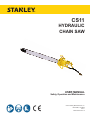
CS11 HYDRAULIC CHAIN SAW USER MANUAL Safety, Operation and Maintenance © 2014 Stanley Black & Decker, Inc. New Britain, CT 06053 U.S.A. 66379 2/2015 Ver. 10 DECLARATION OF CONFORMITY DECLARATION OF CONFORMITY ÜBEREINSTIMMUNGS-ERKLARUNG DECLARATION DE CONFORMITE CEE DECLARACION DE CONFORMIDAD DICHIARAZIONE DI CONFORMITA Hydraulic Tools ______________________________________________________________________ I, the undersigned: Ich, der Unterzeichnende: Je soussigné: El abajo firmante: lo sottoscritto: Weisbeck, Andy Surname and First names/Familiennname und Vornamen/Nom et prénom/Nombre y apellido/Cognome e nome hereby declare that the equipment specified hereunder: bestätige hiermit, daß erklaren Produkt genannten Werk oder Gerät: déclare que l’équipement visé ci-dessous: Por la presente declaro que el equipo se especifica a continuación: Dichiaro che le apparecchiature specificate di seguito: Chain Saw, Hydraulic 1. Category: Kategorie: Catégorie: Categoria: Categoria: 2. Make/Marke/Marque/Marca/Marca 3. Type/Typ/Type/Tipo/Tipo: 4. Serial number of equipment: Seriennummer des Geräts: Numéro de série de l’équipement: Numero de serie del equipo: Matricola dell´attrezzatura: Stanley CS113NO001 All Has been manufactured in conformity with Wurde hergestellt in Übereinstimmung mit Est fabriqué conformément Ha sido fabricado de acuerdo con E’ stata costruita in conformitá con Directive/Standards Richtlinie/Standards Directives/Normes Directriz/Los Normas Direttiva/Norme No. Nr Numéro No n. Approved body Prüfung durch Organisme agréé Aprobado Collaudato ISO ISO ISO ISO ISO ISO Machinery Directive 3744:2010 20643:2005 7915:1991 6534:2007 8334:2007 10726:1992 2006/42/EC:2006 Self Self Self Self Self Self Self 5. Special Provisions: None Spezielle Bestimmungen: Dispositions particulières: Provisiones especiales: Disposizioni speciali: 6. Representative in the Union: Patrick Vervier, Stanley Dubuis 17-19, rue Jules Berthonneau-BP 3406 41034 Blois Cedex, France. Vertreter in der Union/Représentant dans l’union/Representante en la Union/Rappresentante presso l’Unione Done at/Ort/Fait à/Dado en/Fatto a Stanley Hydraulic Tools, Milwaukie, Oregon USA Signature/Unterschrift/Signature/Firma/Firma Position/Position/Fonction/Cargo/Posizione 2 ► CS11 User Manual Director of Product Development Date/Datum/le/Fecha/Data 1-4-11 TABLE OF CONTENTS DECLARATION OF CONFORMITY...........................................................................................................................2 SAFETY SYMBOLS...................................................................................................................................................4 SAFETY PRECAUTIONS...........................................................................................................................................5 ELECTRICAL HAZARDS...........................................................................................................................................7 TOOL STICKERS & TAGS.........................................................................................................................................9 HOSE TYPES...........................................................................................................................................................10 HOSE RECOMMENDATIONS................................................................................................................................. 11 FIGURE 1. TYPICAL HOSE CONNECTIONS...................................................................................................... 11 HTMA REQUIREMENTS..........................................................................................................................................12 OPERATION.............................................................................................................................................................13 FIGURE 2. FELLING A TREE...............................................................................................................................14 FIGURE 3. CROSSCUTTING LOGS WITH PRESSURE ON TOP .....................................................................15 FIGURE 4. CROSSCUTTING LOGS LARGER THAN BAR LENGTH WITH PRESSURE ON TOP.................... 15 FIGURE 5. CROSSCUTTING LOGS/LIMBS WITH PRESSURE ON BOTTOM.................................................. 16 FIGURE 6. CROSSCUTTING LOGS LARGER THAN BAR LENGTH WITH PRESSURE ON BOTTOM............ 16 TOOL PROTECTION & CARE.................................................................................................................................18 TROUBLESHOOTING.............................................................................................................................................19 UNDERWATER TOOLS DEPTH GUIDELINE..........................................................................................................20 SPECIFICATIONS....................................................................................................................................................21 ACCESSORIES.......................................................................................................................................................21 SERVICE TOOLS.....................................................................................................................................................21 CS11 PARTS ILLUSTRATION..................................................................................................................................22 CS11 PARTS LIST....................................................................................................................................................23 IMPORTANT To fill out a Product Warranty Validation form, and for information on your warranty, visit Stanleyhydraulics.com and select the Company tab, Warranty. (NOTE: The warranty Validation record must be submitted to validate the warranty). SERVICING: This manual contains safety, operation, and routine maintenance instructions. Servicing of hydraulic tools, other than routine maintenance, must be performed by an authorized and certified dealer. Please read the following warning. WARNING SERIOUS INJURY OR DEATH COULD RESULT FROM THE IMPROPER REPAIR OR SERVICE OF THIS TOOL. REPAIRS AND / OR SERVICE TO THIS TOOL MUST ONLY BE DONE BY AN AUTHORIZED AND CERTIFIED DEALER. For the nearest authorized and certified dealer, call Stanley Hydraulic Tools at the number listed on the back of this manual and ask for a Customer Service Representative. CS11 User Manual ◄ 3 SAFETY SYMBOLS Safety symbols and signal words, as shown below, are used to emphasize all operator, maintenance and repair actions which, if not strictly followed, could result in a life-threatening situation, bodily injury or damage to equipment. This is the safety alert symbol. It is used to alert you to potential personal injury hazards. Obey all safety messages that follow this symbol to avoid possible injury or death. DANGER This safety alert and signal word indicate an imminently hazardous situation which, if not avoided, will result in death or serious injury. WARNING This safety alert and signal word indicate a potentially hazardous situation which, if not avoided, could result in death or serious injury. CAUTION This safety alert and signal word indicate a potentially hazardous situation which, if not avoided, could result in death or serious injury. CAUTION This signal word indicates a potentially hazardous situation which, if not avoided, may result in property damage. NOTICE This signal word indicates a situation which, if not avoided, will result in damage to the equipment. IMPORTANT This signal word indicates a situation which, if not avoided, may result in damage to the equipment. Always observe safety symbols. They are included for your safety and for the protection of the tool. LOCAL SAFETY REGULATIONS Enter any local safety regulations here. Keep these instructions in an area accessible to the operator and maintenance personnel. 4 ► CS11 User Manual SAFETY PRECAUTIONS Tool operators and maintenance personnel must always comply with the safety precautions given in this manual and on the stickers and tags attached to the tool and hose. 140 °F/60 °C. Operation at higher temperatures can cause higher than normal temperatures at the tool which can result in operator discomfort. • Do not operate a damaged, improperly adjusted, or incompletely assembled chain saw. Be sure that the chain stops moving when the control trigger is released. Supervising personnel should develop additional precautions relating to the specific work area and local safety regulations. If so, place the added precautions in the space provided in this manual. • Never wear loose clothing that can get entangled in the working parts of the tool. • The model CS11 Hydraulic Chain Saw will provide safe and dependable service if operated in accordance with the instructions given in this manual. Read and understand this manual and any stickers and tags attached to the tool and hose before operation. Failure to do so could result in personal injury or equipment damage. Keep all parts of your body away from the chain saw and maintain proper footing and balance at all times. • Do not rely exclusively upon the safety devices built into the saw. As a chain saw user, several steps must be taken to keep your cutting jobs free from accidents or injury. • With basic understanding of kickback, you can reduce or eliminate the element of surprise. Sudden surprise contributes to accidents. • To avoid personal injury or equipment damage, all tool repair, maintenance and service must only be performed by authorized and properly trained personnel. • Keep a good firm grip on the saw with both hands, the right hand on the rear handle and the left hand on the front handle when operating the saw. Use a firm grip with thumbs and fingers encircling the chain saw handles. A firm grip will help reduce kickback and maintain control of the saw. Do not let go. These safety precautions are given for your safety. Review them carefully before operating the tool and before performing general maintenance or repairs. • The operator must start in a work area without bystanders. Flying debris can cause serious injury. • Do not operate the tool unless thoroughly trained or under the supervision of an instructor. Establish a training program for all operators to ensure safe operation. • Always wear safety equipment such as goggles, ear and head protection, and safety shoes at all times when operating the tool. Use gloves and aprons when necessary. • Make sure the area in which you are cutting is free of obstructions. Never allow the nose of the guide bar to contact the log, branch or any obstruction that can be accidently hit while operating the saw. • The operator must be familiar with all prohibited work areas such as excessive slopes and dangerous terrain conditions. • • Do not inspect, clean or replace any part(s) if the hydraulic power source is connected. Do not inspect or clean the tool while the hydraulic power source is connected. Accidental engagement of the tool can cause serious injury. • Always connect hoses to the tool hose couplers before energizing the hydraulic power source. Be sure all hose connections are tight and are in good condition. • Do not operate the tool at oil temperatures above Warning: Use of this tool on certain materials during demolition could generate dust potentially containing a variety of hazardous substances such as asbestos, silica or lead. Inhalation of dust containing these or other hazardous substances could result in serious injury, cancer or death. Protect yourself and those around you. Research and understand the materials you are cutting. Follow correct safety procedures and comply with all applicable national, state or provisional health and safety regulations relating to them, including, if appropriate arranging for the safe disposal of the materials by a qualified person. • CS11 User Manual ◄ 5 SAFETY PRECAUTIONS • Never start the tool while it is lying on the ground. • Cut at rated operating speeds (gpm). • Do not overreach or cut above shoulder height. • Follow the manufacturer’s sharpening and maintenance instructions for the saw chain. • Only use replacement bars and chains specified by Stanley Hydraulic Tools. Chains must meet the requirements of ANSI B175.1 for low kickback performance. • Always be well rested and mentally alert before operating the chain saw. • Do not allow other persons to be near the chain saw when starting or cutting with the chain saw. Keep bystanders and animals out of the work area. • Do not starting cutting until you have a clear work area, secure footing and a planned escape path from a falling tree. • Carry the saw with the unit de-energized and the bar and chain to the rear of your body. • Use extreme caution when cutting small size brush and saplings. Twigs may catch the saw chain and be whipped toward the operator or pull the operator off balance. 6 ► CS11 User Manual • When cutting a limb that is under tension, be alert for spring-back so that you will not be struck when the tension on the limb is released. • Keep the handles dry, clean and free of oil. • Do not operate a chain saw while in a tree unless you have been specially trained to do so. • When using tools near energized transmission lines, be sure to use only hoses labeled and certified nonconductive. • Turn off the power unit or move the hydraulic control valve to neutral before setting the saw down. • Use a guide bar scabbard when transporting the saw. • Know the location of buried or covered electrical services before starting work. • The spiked bumper (bucking cleat) must be installed for felling operations. ELECTRICAL HAZARDS The following guidelines must be followed to prevent accidental contact with overhead electrical conductors and/or communication wires and cables. (ref. ANSI Z133.1-2000) WORKING IN PROXIMITY TO ELECTRICAL HAZARDS An inspection shall be made by a qualified arborist to determine whether an electrical hazard exists before climbing, or otherwise entering, or performing work in or on a tree. Only qualified line-clearance arborists or qualified lineclearance arborist trainees shall be assigned to work where an electrical hazard exists. Qualified line-clearance arborist trainees shall be under the direct supervision of qualified line-clearance arborist. A second qualified line-clearance arborists or line-clearance arborist trainees shall be within vision or voice communication during line-clearing operations aloft when line-clearance arborists or line-clearance arborist trainees must approach closer than 10 feet (3.05 me- ters) to any energized electrical conductor in excess of 750 volts (primary conductor) or when: 1. Branches or limbs being removed cannot first be cut (with a pole pruner/pole saw) to sufficiently clear electrical conductors, so as to avoid contact. 2. Roping is required to remove branches or limbs from such electrical conductors. This does not apply to individuals working on behalf of, or employed by, electrical system owners/operators engaged in line-clearing operations incidental to their normal occupation. Qualified line-clearance arborists and line-clearance arborist trainees shall maintain minimum approach distances from energized electrical conductors in accordance with Table 1. All other arborists shall maintain a minimum approach distance from energized electrical conductors in accordance with Table 2. Branches hanging on an energized electrical conductor shall be removed using non-conductive equipment. Table 1 – Minimum approach distances from energized conductors for qualified line-clearance arborists and qualified line- clearance arborist trainees. Nominal Voltage (kV phase-to-phase) 0.05 to 1.0 Includes 1910.269 elevation factor, sea level to 5000 ft1 ft-in m Avoid contact Includes 1910.269 elevation factor, 5001 – 10,000 ft1 Includes 1910.269 elevation factor, 10,000 – 14,000 ft1 ft-in ft-in m Avoid contact m Avoid contact 1.1 to 15.0 2–04 0.71 2–08 0.81 2–10 0.86 15.1 to 36.0 2-09 0.84 3–02 0.97 3–05 1.04 36.1 to 46.0 3–00 0.92 3–05 1.04 3–09 1.14 46.1 to 72.5 3–09 1.14 4–03 1.30 4–07 1.40 72.6 to 121.0 4–06 1.37 5–02 1.58 5–07 1.70 138.0 to 145.0 5–02 1.58 5–11 1.80 6–05 1.96 161.0 to 169.0 6-00 1.83 6–10 2.08 7–05 2.26 230.0 to 242.0 7–11 2.41 9–00 2.75 9–09 2.97 345.0 to 362.0 13–02 4.02 15–00 4.58 16–03 4.96 500.0 to 550.0 19–00 5.80 21–09 6.63 23–06 7.17 765.0 to 800.0 27–04 8.34 31–03 9.53 33–10 10.32 1. Exceeds phase-to-ground; elevation factor per 29 CFR 1910.269. CS11 User Manual ◄ 7 ELECTRICAL HAZARDS Table 2 – Minimum approach distances to energized conductors for persons other than qualified lineclearance arborists and qualified line- clearance arborist trainees. Nominal Voltage kV phase-to-phase Distance 1 ft-in m 0.0 – 1.0 10–00 3.05 1.1 – 15.0 10–00 3.05 15.1 – 36.0 10–00 3.05 36.1 – 50.0 10–00 3.05 50.1 – 72.5 10–09 3.28 72.6 – 121.0 12–04 3.76 138.0 – 145.0 13–02 4.00 161.0 – 169.0 14–00 4.24 230.0 – 242.0 16–05 4.97 345.0 – 362.0 20–05 6.17 500.0 – 550.0 26–08 8.05 785.0 – 800.0 35–00 10.55 1. Exceeds phase-to-ground. The tie-in position should be above the work area and located in such a way that a slip would swing the arborist away from any energized electrical conductors or other identified hazard. While climbing, the arborist should climb on the side of the tree that is away from energized electrical conductors as required in Tables 1 and 2. 8 ► CS11 User Manual Footwear, including lineman’s overshoes, having electrical-resistant soles, shall not be considered as providing any measure of safety from electrical hazards. Rubber gloves, with or without leather or other protective covering, shall not be considered as providing any measure of safety from electrical hazards. Ladders, platforms and aerial devices, including insulated aerial devices, shall be subject to minimum approach distances in Table 1 and 2. Aerial devices and attached equipment (such as chippers) contacting energized electrical conductors shall be considered energized. Contact shall be avoided, except where emergency rescue procedures are being carried out. Emergency rescue should be performed in accordance with 4.3. STORM WORK AND EMERGENCY CONDITIONS-LINE CLEARANCE Line clearance shall not be performed during adverse weather conditions such as thunderstorms, high winds and snow and ice storms. Qualified line-clearance arborists and qualified lineclearance arborists trainees performing line clearance in the aftermath of a storm or under similar conditions shall be trained in the special hazards associated with this type of work. Line-clearance operations shall be suspended when storm work or emergency conditions develop involving energized electrical conductors. Electrical system owners/operators shall be notified immediately. TOOL STICKERS AND TAGS E F 40 LPM @ 138 BAR EHTMA CATEGORY 28409 Composite Decal (CE Models Only) ___ LPM @ ___ BAR EHTMA CATEGORY 12535 12536 Circuit Type E Decal Circuit Type F Decal 02751 (CE Models Only) (CE Models Only) Name Tag 04746 Auto Oiler Decal DANGER 13907 as non-conductive when using hydraulic tools on Kickback Warning Decal 28323 CE Decal Failure to use hydraulic hose labeled and certified or near electric lines may result in death or serious injury. 29036 03790 Sound Power Level Decal GPM Decal For proper and safe operation read owners manual and mwke sure that you have been properly ELECTROCUTION HAZARD trained in correct procedures required for work on or around electric lines. 12412 Electrical Warning Decal D A N G E R 1. FAILURE TO USE HYDRAULIC HOSE LABELED AND CERTIFIED AS NON-CONDUCTIVE WHEN USING HYDRAULIC TOOLS ON OR NEAR ELECTRICAL LINES MAY RESULT IN DEATH OR SERIOUS INJURY. BEFORE USING HOSE LABELED AND CERTIFIED AS NONCONDUCTIVE ON OR NEAR ELECTRIC LINES BE SURE THE HOSE IS MAINTAINED AS NON-CONDUCTIVE. THE HOSE SHOULD BE REGULARLY TESTED FOR ELECTRIC CURRENT LEAKAGE IN ACCORDANCE WITH YOUR SAFETY DEPARTMENT INSTRUCTIONS. 2. NOTE THE INFORMATION LISTED ON THE STICKERS SHOWN, MUST BE LEGIBLE AT ALL TIMES. REPLACE DECALS IF THEY BECOME WORN OR DAMAGED. REPLACEMENTS ARE AVAILABLE FROM YOUR LOCAL STANLEY DISTRIBUTOR. The safety tag (P/N 15875) at right is attached to the tool when shipped from the factory. Read and understand the safety instructions listed on this tag before removal. We suggest you retain this tag and attach it to the tool when not in use. A HYDRAULIC LEAK OR BURST MAY CAUSE OIL INJECTION INTO THE BODY OR CAUSE OTHER SEVERE PERSONAL INJURY. A. DO NOT EXCEED SPECIFIED FLOW AND PRESSURE FOR THIS TOOL. EXCESS FLOW OR PRESSURE MAY CAUSE A LEAK OR BURST. B. DO NOT EXCEED RATED WORKING PRESSURE OF HYDRAULIC HOSE USED WITH THIS TOOL. EXCESS PRESSURE MAY CAUSE A LEAK OR BURST. C. CHECK TOOL HOSE COUPLERS AND CONNECTORS DAILY FOR LEAKS. DO NOT FEEL FOR LEAKS WITH YOUR HANDS. CONTACT WITH A LEAK MAY RESULT IN SEVERE PERSONAL INJURY. D A N G E R D. DO NOT LIFT OR CARRY TOOL BY THE HOSES. DO NOT ABUSE HOSE. DO NOT USE KINKED, TORN OR DAMAGED HOSE. 3. MAKE SURE HYDRAULIC HOSES ARE PROPERLY CONNECTED TO THE TOOL BEFORE PRESSURING SYSTEM. SYSTEM PRESSURE HOSE MUST ALWAYS BE CONNECTED TO TOOL “IN” PORT. SYSTEM RETURN HOSE MUST ALWAYS BE CONNECTED TO TOOL “OUT” PORT. REVERSING CONNECTIONS MAY CAUSE REVERSE TOOL OPERATION WHICH CAN RESULT IN SEVERE PERSONAL INJURY. 4. DO NOT CONNECT OPEN-CENTER TOOLS TO CLOSEDCENTER HYDRAULIC SYSTEMS. THIS MAY RESULT IN LOSS OF OTHER HYDRAULIC FUNCTIONS POWERED BY THE SAME SYSTEM AND/OR SEVERE PERSONAL INJURY. 5. BYSTANDERS MAY BE INJURED IN YOUR WORK AREA. KEEP BYSTANDERS CLEAR OF YOUR WORK AREA. 6. WEAR HEARING, EYE, FOOT, HAND AND HEAD PROTECTION. 7. TO AVOID PERSONAL INJURY OR EQUIPMENT DAMAGE, ALL TOOL REPAIR MAINTENANCE AND SERVICE MUST ONLY BE PERFORMED BY AUTHORIZED AND PROPERLY TRAINED PERSONNEL. I M P O R T A N T I M P O R T A N T READ OPERATION MANUAL AND SAFETY INSTRUCTIONS FOR THIS TOOL BEFORE USING IT. READ OPERATION MANUAL AND SAFETY INSTRUCTIONS FOR THIS TOOL BEFORE USING IT. USE ONLY PARTS AND REPAIR PROCEDURES APPROVED BY STANLEY AND DESCRIBED IN THE OPERATION MANUAL. USE ONLY PARTS AND REPAIR PROCEDURES APPROVED BY STANLEY AND DESCRIBED IN THE OPERATION MANUAL. TAG TO BE REMOVED ONLY BY TOOL OPERATOR. TAG TO BE REMOVED ONLY BY TOOL OPERATOR. SEE OTHER SIDE SEE OTHER SIDE SAFETY TAG P/N 15875 (shown smaller then actual size) CS11 User Manual ◄ 9 HOSE TYPES The rated working pressure of the hydraulic hose must be equal to or higher than the relief valve setting on the hydraulic system. There are three types of hydraulic hose that meet this requirement and are authorized for use with Stanley Hydraulic Tools. They are: Certified non-conductive — constructed of thermoplastic or synthetic rubber inner tube, synthetic fiber braid reinforcement, and weather resistant thermoplastic or synthetic rubber cover. Hose labeled certified nonconductive is the only hose authorized for use near electrical conductors. Wire-braided (conductive) — constructed of synthetic rubber inner tube, single or double wire braid reinforcement, and weather resistant synthetic rubber cover. This hose is conductive and must never be used near electrical conductors. Fabric-braided (not certified or labeled non-conductive) — constructed of thermoplastic or synthetic rubber inner tube, synthetic fiber braid reinforcement, and weather resistant thermoplastic or synthetic rubber cover. This hose is not certified non-conductive and must never be used near electrical conductors. HOSE SAFETY TAGS To help ensure your safety, the following DANGER tags are attached to all hose purchased from Stanley Hydraulic Tools. DO NOT REMOVE THESE TAGS. If the information on a tag is illegible because of wear or damage, replace the tag immediately. A new tag may be obtained from your Stanley Distributor. THE TAG SHOWN BELOW IS ATTACHED TO “CERTIFIED NON-CONDUCTIVE” HOSE DO NOT REMOVE THIS TAG FAILURE TO USE HYDRAULIC HOSE LABELED AND CERTIFIED AS NON-CONDUCTIVE WHEN USING HYDRAULIC TOOLS ON OR NEAR ELECTRIC LINES MAY RESULT IN DEATH OR SERIOUS INJURY. FOR PROPER AND SAFE OPERATION MAKE SURE THAT YOU HAVE BEEN PROPERLY TRAINED IN CORRECT PROCEDURES REQUIRED FOR WORK ON OR AROUND ELECTRIC LINES. 2. BEFORE USING HYDRAULIC HOSE LABELED AND CERTIFIED AS NON-CONDUCTIVE ON OR NEAR ELECTRIC LINES. WIPE THE ENTIRE LENGTH OF THE HOSE AND FITTING WITH A CLEAN DRY ABSORBENT CLOTH TO REMOVE DIRT AND MOISTURE AND TEST HOSE FOR MAXIMUM ALLOWABLE CURRENT LEAKAGE IN ACCORDANCE WITH SAFETY DEPARTMENT INSTRUCTIONS. 3. DO NOT EXCEED HOSE WORKING PRESSURE OR ABUSE HOSE. IMPROPER USE OR HANDLING OF HOSE COULD RESULT IN BURST OR OTHER HOSE FAILURE. KEEP HOSE AS FAR AWAY AS POSSIBLE FROM BODY AND DO NOT PERMIT DIRECT CONTACT DURING USE. CONTACT AT THE BURST CAN CAUSE BODILY INJECTION AND SEVERE PERSONAL INJURY. 4. HANDLE AND ROUTE HOSE CAREFULLY TO AVOID KINKING, ABRASION, CUTTING, OR CONTACT WITH HIGH TEMPERATURE SURFACES. DO NOT USE IF KINKED. DO NOT USE HOSE TO PULL OR LIFT TOOLS, POWER UNITS, ETC. 5. CHECK ENTIRE HOSE FOR CUTS CRACKS LEAKS ABRASIONS, BULGES, OR DAMAGE TO COUPLINGS IF ANY OF THESE CONDITIONS EXIST, REPLACE THE HOSE IMMEDIATELY. NEVER USE TAPE OR ANY DEVICE TO ATTEMPT TO MEND THE HOSE. 6. AFTER EACH USE STORE IN A CLEAN DRY AREA. SEE OTHER SIDE SIDE 1 SEE OTHER SIDE (Shown smaller than actual size) DO NOT REMOVE THIS TAG D A N G E R D A N G E R 1. SIDE 2 D A N G E R D A N G E R 1. DO NOT USE THIS HYDRAULIC HOSE ON OR NEAR ELECTRIC LINES. THIS HOSE IS NOT LABELED OR CERTIFIED AS NON-CONDUCTIVE. USING THIS HOSE ON OR NEAR ELECTRICAL LINES MAY RESULT IN DEATH OR SERIOUS INJURY. 5. CHECK ENTIRE HOSE FOR CUTS CRACKS LEAKS ABRASIONS, BULGES, OR DAMAGE TO COUPLINGS IF ANY OF THESE CONDITIONS EXIST, REPLACE THE HOSE IMMEDIATELY. NEVER USE TAPE OR ANY DEVICE TO ATTEMPT TO MEND THE HOSE. 2. FOR PROPER AND SAFE OPERATION MAKE SURE THAT YOU HAVE BEEN PROPERLY TRAINED IN CORRECT PROCEDURES REQUIRED FOR WORK ON OR AROUND ELECTRIC LINES. 6. AFTER EACH USE STORE IN A CLEAN DRY AREA. 3. DO NOT EXCEED HOSE WORKING PRESSURE OR ABUSE HOSE. IMPROPER USE OR HANDLING OF HOSE COULD RESULT IN BURST OR OTHER HOSE FAILURE. KEEP HOSE AS FAR AWAY AS POSSIBLE FROM BODY AND DO NOT PERMIT DIRECT CONTACT DURING USE. CONTACT AT THE BURST CAN CAUSE BODILY INJECTION AND SEVERE PERSONAL INJURY. 4. HANDLE AND ROUTE HOSE CAREFULLY TO AVOID KINKING, CUTTING, OR CONTACT WITH HIGH TEMPERATURE SURFACES. DO NOT USE IF KINKED. DO NOT USE HOSE TO PULL OR LIFT TOOLS, POWER UNITS, ETC. SEE OTHER SIDE SEE OTHER SIDE SIDE 1 SIDE 2 (Shown smaller than actual size) 10 ► CS11 User Manual DO NOT REMOVE THIS TAG DO NOT REMOVE THIS TAG THE TAG SHOWN BELOW IS ATTACHED TO “CONDUCTIVE” HOSE. All hydraulic hose must meet or exceed specifications as set forth by SAE J517. All hydraulic hose must have at least a rated minimum working pressure equal to the maximum hydraulic system relief valve setting. This chart is intended to be used for hydraulic tool applications only based on Stanley Hydraulic Tools tool operating requirements and should not be used for any other applications. The chart to the right shows recommended minimum hose diameters for various hose lengths based on gallons per minute (gpm)/ liters per minute (lpm). These recommendations are intended to keep return line pressure (back pressure) to a minimum acceptable level to ensure maximum tool performance. Tool to Hydraulic Circuit Hose Recommendations 15-34 MM Inside Diameter INCH USE (Press/Return) PSI up to 10 up to 3 3/8 10 Both 2250 49-60 13-16 FLOW >>> RETURN <<< FLOW PRESSURE 26-100 up to 25 100-200 51-100 up to 50 100-300 51-100 up to 50 26-100 up to 25 8-30 up to 8 30-60 15-30 up to 15 30-90 15-30 up to 15 7.5-30 up to 7.5 Figure 1. Typical Hose Connections 49-60 38-49 10-13 13-16 19-40 5-10.5 38-49 19-40 5-10.5 10-13 19-40 5-10.5 38-49 15-23 10-13 15-23 4-6 19 25.4 16 19 19 25.4 5/8 3/4 3/4 1 19 3/4 1 16 3/4 16 19 3/4 5/8 16 5/8 5/8 16 13 13 10 5/8 1/2 1/2 3/8 Return Pressure Return Pressure Return Pressure Return Pressure Both Return Pressure Both Both Both Both 2500 2500 2500 2500 2500 2500 2500 2500 2500 2500 2500 2500 2500 2500 2500 175 175 175 175 175 175 175 175 175 175 175 175 175 175 175 155 BAR Min. Working Pressure Certified Non-Conductive Hose - Fiber Braid - for Utility Bucket Trucks METERS Hose Lengths FEET Conductive Hose - Wire Braid or Fiber Braid -DO NOT USE NEAR ELECTRICAL CONDUCTORS 4-6 4-9 LPM Oil Flow GPM HOSE RECOMMENDATIONS CS11 User Manual ◄ 11 HTMA / EHTMA REQUIREMENTS HTMA / EHTMA REQUIREMENTS HTMA HYDRAULIC SYSTEM REQUIREMENTS TYPE I Nominal Operating Pressure (at the power supply outlet) 4-6 gpm (15-23 lpm) 1500 psi (103 bar) TOOL TYPE TYPE II TYPE RR 7-9 gpm (26-34 lpm) 1500 psi (103 bar) 9-10.5 gpm (34-40 lpm) 1500 psi (103 bar) System relief valve setting (at the power supply outlet) 2100-2250 psi (145-155 bar) 2100-2250 psi (145-155 bar) 2200-2300 psi (152-159 bar) 2100-2250 psi (145-155 bar) Maximum back pressure (at tool end of the return hose) 250 psi (17 bar) 250 psi (17 bar) 250 psi (17 bar) 250 psi (17 bar) Measured at a max. fluid viscosity of: (at min. operating temperature) 400 ssu* 400 ssu* 400 ssu* 400 ssu* (82 centistokes) (82 centistokes) (82 centistokes) (82 centistokes) Temperature: Sufficient heat rejection capacity to limit max. fluid temperature to: (at max. expected ambient temperature) 140° F (60° C) Flow Range 140° F (60° C) 140° F (60° C) TYPE III 11-13 gpm (42-49 lpm) 1500 psi (103 bar) 140° F (60° C) 3 hp 5 hp 6 hp 7 hp Min. cooling capacity at a temperature (2.24 kW) (3.73 kW) (5.22 kW) (4.47 kW) difference of between ambient and fluid 40° F 40° F 40° F 40° F temps (22° C) (22° C) (22° C) (22° C) NOTE: Do not operate the tool at oil temperatures above 140° F (60° C). Operation at higher temperatures can cause operator discomfort at the tool. Filter Min. full-flow filtration Sized for flow of at least: (For cold temp. startup and max. dirt-holding capacity) 25 microns 30 gpm (114 lpm) Hydraulic fluid Petroleum based (premium grade, anti-wear, non-conductive) Viscosity (at min. and max. operating temps) 100-400 ssu* 25 microns 30 gpm (114 lpm) 25 microns 30 gpm (114 lpm) 100-400 ssu* 100-400 ssu* (20-82 centistokes) 25 microns 30 gpm (114 lpm) 100-400 ssu* NOTE: When choosing hydraulic fluid, the expected oil temperature extremes that will be experienced in service determine the most suitable temperature viscosity characteristics. Hydraulic fluids with a viscosity index over 140 will meet the requirements over a wide range of operating temperatures. *SSU = Saybolt Seconds Universal EHTMA HYDRAULIC SYSTEM REQUIREMENTS CLASSIFICATION B C D Nominal Operating Pressure (at the power supply outlet) 3.5-4.3 gpm (13.5-16.5 lpm) 1870 psi (129 bar) 4.7-5.8 gpm (18-22 lpm) 1500 psi (103 bar) 7.1-8.7 gpm (27-33 lpm) 1500 psi (103 bar) 9.5-11.6 gpm (36-44 lpm) 1500 psi (103 bar) 11.8-14.5 gpm (45-55 lpm) 1500 psi (103 bar) System relief valve setting (at the power supply outlet) 2495 psi (172 bar) 2000 psi (138 bar) 2000 psi (138 bar) 2000 psi (138 bar) 2000 psi (138 bar) Flow Range NOTE: These are general hydraulic system requirements. See tool specification page for tool specific requirements 12 ► CS11 User Manual OPERATION PREOPERATION PROCEDURES HYDRAULIC SYSTEM REQUIREMENTS The hydraulic system should provide a flow of 10-14 gpm/38-53 Ipm at an operating pressure of 1500-2000 psi/105-140 bar. Recommended relief valve settings are 2100-2250 psi/145-155 bar. The system should have no more than 250 psi/17 bar backpressure measured at the tool end of the operating hoses. The system conditions for measurement are at maximum fluid viscosity of 400 ssu/82 centistokes (minimum operating temperatures). The hydraulic system should have sufficient heat rejection capacity to limit the maximum oil temperature to 140° F/60° C at the maximum expected ambient temperature. The recommended minimum cooling capacity is 7 hp/5.22 kW at a 40 °F/22 °C difference between ambient temperature and oil temperature. The hydraulic system should have a minimum of 25 micron filtration. It is recommended that filter elements be sized for a flow of at least 30 gpm/114 Ipm for cold temperature startup and maximum dirt holding capacity. The hydraulic fluid used should have a viscosity between 100 and 400 ssu/20 and 82 centistokes at the maximum and minimum expected operating temperatures. Petroleum based hydraulic fluids with antiwear properties and a viscosity index over 140 ssu/28 centistokes will meet the recommended requirements over a wide range of operating temperatures. The recommended hose size is .625-inch/16 mm I.D. up to 50 ft/15 m long and .750-inch/20 mm I.D. minimum up to 100 ft/30 m long. CHECK POWER SOURCE 1. Using a calibrated flowmeter and pressure gauge, check that the hydraulic power source develops a flow of 10-14 gpm/38-53 Ipm at 1500-2000 psi/105140 bar. 2. Make certain that the hydraulic power source is equipped with a relief valve set to open at 21002250 psi/145-155 bar. CONNECT HOSES 1. Wipe all hose couplers with a clean lint-free cloth before making connections. 2. Connect the hoses from the hydraulic power source to the tool fittings or quick disconnects. It is good practice to connect return hoses first and disconnect them last to minimize or avoid trapped pressure within the tool. 3. Observe the arrow on the couplers to ensure that the flow is in the proper direction. The female coupler on the tool hose is the inlet (pressure) coupler. 4. Move the hydraulic circuit control valve to the “ON” position to operate the tool. NOTE: If uncoupled hoses are left in the sun, pressure increase inside the hose may make them difficult to connect. Whenever possible, connect the free ends of the hoses together. OPERATING PROCEDURES The following are general wood cutting procedures and techniques. Differences in the terrain, vegetation, and type of wood will make this information more or less valid for particular areas. For advice on specific woodcutting problems or techniques for your area, consult your local Stanley representative or your county agent. They can often provide information that will make your work safer and more productive. CUTTING TIPS 1. Check the lean of the tree. Tie a weight to a piece of string about 2 feet long. Hang the weight in your line of sight. The string is a good vertical line to help you judge the lean of the tree. The tree should fall the way it is leaning. Trees that are straight (leaning no more than 5 degrees) generally can be felled in any direction. 2. Avoid felling across another tree, log, rocks, gully or ridge. Do not fell straight uphill or downhill. Fell the tree diagonally to the hill. Consider the wind direction and velocity. Do not attempt cutting in strong winds. 3. Check the weight distribution. A tree is heavier on the side with the most limbs. It will try to fall on its heavy side. Trim a few limbs to “balance” the tree. 4. Clear the work area. You need a clean area all around the tree for good footing. Get everything out of the area where the tree will fall. Do not cut trees near structures. Because of the danger of electrocution, use extreme care when cutting trees near power lines. 5. Before starting the cut, prepare your escape path. Make sure the escape path is clear of brush and branches. The escape path should be at an angle away from the direction of fall. CS11 User Manual ◄ 13 OPERATION 6. The saw chain should cut with very little pressure applied to the handle. If you have to force the saw to cut or if the cut is not straight, cease cutting immediately to prevent further saw chain and bar damage. See the Maintenance and Adjustments section of this manual for chain replacement or adjustment procedures. 7. Underwater models require daily preventive maintenance. See the Maintenance and Adjust ments section of this manual for these maintenance procedures. FELLING (CUTTING DOWN A TREE) (FIGURE 2) Observe all safety precautions. The spiked bumber (bucking cleat) must be installed for this operation. FELLING OR BACK CUT 5. The felling or back cut is made on the side opposite and at least 2 inches above the horizontal undercut (the felling cut is made higher as the size of the tree increases). Place the saw so the hand guard is close to the tree trunk and the bucking cleat is dug in. 6. Start the cut horizontally. Pivot the bar in until the cut is being made parallel to the notch cut. Cut until the saw is about 1 or 2 inches from the notch. Do not cut through the notch. NOTE: The uncut wood between the felling and notch cuts is called the hinge. The hinge controls the fall of the tree and should be of uniform thickness. 7. As the saw nears the back cut, watch the treetop and the cut for signs of movement. Be alert as soon as the tree starts to move, turn off the saw, pull it from the tree and move away quickly on your escape route. 8. For trees larger than bar length, make two felling cuts. Cut in as far as the bar will go, move to the other side and start the second cut in the same manner as the first while pivoting the saw to complete the felling cut. BUCKING Figure 2. Felling a Tree NOTCHING OR UNDERCUTTING Bucking is the sawing of a log or fallen tree into smaller pieces. 1. Observe all safety precautions. 1. The notching or undercutting cut is made on the side you want the tree to fall. Place the saw so the hand guard is close to the tree trunk and the bucking cleat is dug in. 2. Use both hands. Grip the saw firmly. 2. Start the cut horizontally. Pivot the nose of the bar in last. Cut to about one-quarter of the tree’s diameter. 5. Stand to the left of the saw. 3. Watch out for falling limbs. 4. Make a diagonal cut down to meet the horizontal cut and remove the wood from the notch. 14 ► CS11 User Manual 3. Stand uphill. A log that is cut loose may roll downhill. 4. Keep the chain out of the dirt. Dirt will dull the chain. A dull chain is unsafe. CROSSCUTTING NOTE: Before starting to cut through a log try to imagine what is going to happen. Look out for stresses in the log and cut through the log in such a manner that the guide bar will not get pinched. OPERATION LOGS WITH PRESSURE ON TOP (FIGURE 3) 1. Observe all safety precautions. 2. Begin with an upper cut, down from the top. Do not cut too deeply. A cut of about 1/3 of the log diameter is enough. 3. Finish with a bottom cut. They should meet. Figure 3. Crosscutting Logs with Pressure on Top THICK LOGS LARGER THAN BAR LENGTH WITH PRESSURE ON TOP (FIGURE 4) 1. Observe all safety precautions. 2. Begin by cutting on the opposite side of the log. 3. Pull the saw towards you and cut from the top. 4. Cut from the bottom. Make a boring cut if the log is close to the ground. 5. Finish with a bottom cut. Figure 4. Crosscutting Logs Larger than Bar Length With Pressure on Top CS11 User Manual ◄ 15 OPERATION LOGS/LIMBS WITH PRESSURE ON BOTTOM (FIGURE 5) 1. Observe all safety precautions. 2. Begin with a bottom cut. The depth of the cut should be about 1/3 of the log diameter. 3. Finish with an upper cut, down from the top. The saw cuts should meet. Figure 5. Crosscutting Logs/Limbs with Pressure on Bottom THICK LOGS LARGER THAN BAR LENGTH WITH PRESSURE ON THE BOTTOM (FIGURE 6) 1. Observe all safety precautions. 2. Begin by cutting on the opposite side of the log. 3. Pull the saw towards you and cut from the top. 4. Cut from the bottom. Make a boring cut if the log is close to the ground. 5. Finish with a top cut. PRUNING AND DEBRANCHING 1. Observe all safety precautions. 2. Use both hands. Keep a firm grip. 3. Be alert for kickback. Do not allow the tip of the bar to touch anything while the chain is in motion. 4. Do not cut overhead. Keep the saw below chest level. The chain is too close to your face in this position. 16 ► CS11 User Manual Figure 6. Crosscutting Logs Larger than Bar Length with Pressure on Bottom OPERATION COLD WEATHER OPERATION If the saw is to used during cold weather, preheat the hydraulic fluid at low engine speed. When using the normally recommended oils, oil should be at or above 50 °F/10 °C (400 ssu/ 82 centistokes) before use. Damage to the hydraulic system or saw can result from use with fluid that is too viscous or thick. Cutting frozen wood causes the cutters to wear, crack and break at the back rivet hole unless proper precautions are taken. To extend chain life when cutting in cold weather: 1. Be sure the oiler is working. 2. Keep the chain tensioned and check often. 3. Keep the cutters properly sharpened. Touch up at least every hour. Never force a dull chain to cut. 4. Clean out the bar groove and keep the oil hole open. Turn the bar over to equalize wear on the rails. 5. Always install a new sprocket with a new chain. CS11 User Manual ◄ 17 TOOL PROTECTION & CARE NOTICE In addition to the Safety Precautions found in this manual, observe the following for equipment protection and care. • Make sure all couplers are wiped clean before connection. • The hydraulic circuit control valve must be in the “OFF” position when coupling or uncoupling hydraulic tools. Failure to do so may result in damage to the quick couplers and cause overheating of the hydraulic system. • Always store the tool in a clean dry space, safe from damage or pilferage. • Make sure the circuit PRESSURE hose (with male quick disconnect) is connected to the “IN” port. The circuit RETURN hose (with female quick disconnect) is connected to the opposite port. Do not reverse circuit flow. This can cause damage to internal seals. • Always replace hoses, couplings and other parts with replacement parts recommended by Stanley Hydraulic Tools. Supply hoses must have a minimum working pressure rating of 2500 psi/172 bar. 18 ► CS11 User Manual • Do not exceed the rated flow and pressure. See Specifications page in this manual for correct flow rate and pressure rating. Rapid failure of the internal seals may result. • Always keep critical tool markings, such as warning stickers and tags legible. • Tool repair should be performed by experienced personnel only. • Make certain that the recommended relief valves are installed in the pressure side of the system. • Do not use the tool for applications for which it was not intended. TROUBLESHOOTING If symptoms of poor performance develop, the following chart can be used as a guide to correct the problem. When diagnosing faults in operation of the saw, always make sure the hydraulic power source is supplying the correct hydraulic flow and pressure to the saw as listed in the table. Use a flow meter know to be accurate. Check the flow with the hydraulic fluid temperature at least 80 °F/27 °C. PROBLEM Cuts slow. Bar turns color. CAUSE REMEDY Insufficient fluid flow or low relief Adjust fluid flow to proper gpm. For valve setting. optimum performance adjust relief valve to 2250 psi/155 psi. Chain dull. Sharpen per instructions or replace. Backpressure too high. Should not exceed 250 psi/17 bar at 14 gpm/53 lpm measured at the end of the tool operating hoses. Insufficient oiler flow. Use manual oiler during heavy cuts. Adjust oiler per service instructions. Tool does not run. Power unit not functioning. Check power unit for proper flow and pressure (10 gpm/38 lpm at 1500 psi/104 bar minimum). Coupler or hoses blocked. Remove obstruction. Mechanical failure. Disassemble tool and inspect for damage. Tool runs backwards. Pressure and return reversed. Connect for proper flow direction. Motor shaft rotates clockwise. On/Off trigger is hard to press. Pressure and return reversed. Correct for proper flow direction. Backpressure too high. Should not exceed 250 psi/17 bar at 14 gpm/53 lpm measured at the end of the tool operating hoses. Oil leakage around drive sprocket. Motor shaft seal failure. Replace as required. Make sure that oil present is not the result of excess oiler flow. Oil leakage between rear gear housing and valve handle assembly. Motor face seal failure. Replace as required. Chain continues to move after valve is shut off. Chain is too loose. Tighten chain. Input flow too high. Decrease flow. CS11 User Manual ◄ 19 UNDERWATER TOOLS DEPTH GUIDELINE UNDERWATER MODEL CS113N0001 ONLY Operation Overview Percussive Tools: Breakers, Hammer Drills and Chipping Hammers DO NOT USE HYDRAULIC TOOLS UNDERWATER THAT ARE NOT DESIGNATED AS AN “UNDERWATER” MODEL, OR THIS WILL RESULT IN DAMAGE TO THE TOOL. Diver CAUTION The types of tools are percussive and rotational, each with different characteristics allowing for different depth operation. With percussive tools, the nitrogen accumulator PSI must counter the increase in ambient pressure found at lower depths. Since there is a maximum PSI for percussive tools they are limited to certain depths. Rotational tools do not have accumulators and thus capable of deeper depths. The methods are broken into diver operated or remote operated vehicle (ROV). ROV's can reach lower depths and with an on-board hydraulic power source that is depth compensated, can operate hydraulic tools at depths of thousands of feet. ROV operation is still limited to the tool, for example a percussive tool has the same depth limitation whether ROV or diver operated. 20 ► CS11 User Manual ROV For underwater hydraulic tools the applications are broken down into four quadrants depending on type of tool and method of operation. Max Depth: 500' limitations due to accumulator PSI max (increase 40 PSI for every 100') Tools: Breakers, Hammer Drills and Chipping Hammers Max Depth: 500' limitations due to accumulator PSI max (increase 40 PSI for every 100') Rotational Tools: Grinders, Saws, Chain Saws Max Depth: 1000' Reference hose sizing guide below Tools: Grinders, Saws, Chain Saws Max Depth: 1000' Reference hose sizing guide below Recommended Hose Diameters Depth (ft) 100 300 600 1000 8 GPM 5/8” 3/4” 1” 1” 12 GPM 5/8” 1” 1” 1-1/4” SPECIFICATIONS Capacity.................................................................................. 24, 32, 36, 42 inches/61, 81, 91, 106 cm Cut Lengths Weight......................................................................................................................................................14 lbs/6.3 kg Length................................................................................................................................................17 inches/43 cm Width....................................................................................................................................................9 inches/23 cm Pressure.......................................................................................................................... 1500–2000 psi/105–140 bar Flow Range.............................................................................................................................. 10–14 gpm/38–53 lpm Optimum Flow...................................................................................................................................... 14 gpm/53 lpm Porting.....................................................................................................................................................8 SAE O-ring Connect Size and Type..................................................................................................1/2 inch Male Pipe Hose End Hose Whips............................................................................................................................................................ Yes Motor............................................................................................................................................................. Hyrevz™ Kickback Reduction Features......................................................Front Hand Guard, Low Inertia Motor/Drive System SOUND AND VIBRATION DECLARATION Test conducted on CS113N0001, S/N 361 operated at 10-14 gpm input Measured A-weighted sound power level, Lwa (ref. 1pW) in decibels 97.2 dBA Uncertainty, Kwa, in decibels 3 dBA Measured A-weighted sound pressure level, Lpa (ref. 20 µPa) at operator’s position, in decibels 89.2 dBA Uncertainty, Kpa, in decibels 3 dBA Values determined according to noise test code given in ISO 15744, using the basic standard ISO 3744 NOTE: The sum of a measured noise emission value and its associated uncertainty represents an upper boundary of the range of values which is likely to occur in measurements. Declared vibration emission value in accordance with EN 12096 Measured vibration emission value (Main Handle): a 5.2 m/sec² Uncertainty: K 1.0 m/sec² Measured vibration emission value (Assist Handle): a 4.1 m/sec² Uncertainty: K 1.0 m/sec² Values determined according to ISO 7505, ISO 8662-1, ISO 5349-1,2 ACCESSORIES 24-inch Saw Chain.............................................................................................................................................72951 24-inch Cut Sprocket Nose Bar..........................................................................................................................72947 32-inch Saw Chain.............................................................................................................................................72952 32-inch Cut Sprocket Nose Bar..........................................................................................................................72948 36-inch Saw Chain.............................................................................................................................................72953 36-inch Cut Sprocket Nose Bar..........................................................................................................................72949 42-inch Saw Chain.............................................................................................................................................72954 42-inch Cut Sprocket Nose Bar..........................................................................................................................72950 Stud Kit To Convert old CS11’s To New Bar (Includes 2-Stud’s, 2 Nuts, 2 Washers & Inst Sheet).................... 72960 This new bar change started end of May 2012 SERVICE TOOLS Motor Seal Kit, 3 Pc (for P/N 03272 Motor)........................................................................................................03327 Repair Kit........................................................................................................................................................03328 O-Ring Tool Kit...................................................................................................................................................04337 Bearing Installation Tool.....................................................................................................................................05044 Motor Seal Kit, 2 Pc (for P/N 21444 Motor)........................................................................................................10569 Repair Kit........................................................................................................................................................10570 Motor Seal Kit, 2 Pc (for P/N 21443 Motor)........................................................................................................10571 Repair Kit........................................................................................................................................................10572 CS11 User Manual ◄ 21 CS11 PARTS ILLUSTRATION NOTE: If you have a CS11 built in 2011 or earlier and you are replacing either the Spool (item 36) or the Plug (item 54) you must replace 3 items. The spool and plug have changed along with the addition of a Poppet (item 92). The 3 items that should be replaced together are the Spool (item 36), Plug (item 54) and add a Poppet (item 92). The old spool 02925 and old plug 09437 can not be used with the new spool and plug shown on this parts list. 22 ► CS11 User Manual CS11 PARTS LIST ITEM NO. P/N QTY 1 00612 8 ITEM NO. P/N QTY CAPSCREW 52 02916 1 SPRING 01604 1 O-RING * DESCRIPTION DESCRIPTION 2 31849 1 REAR GEAR HOUSING 53 3 06316 4 BUSHING 54 31137 1 4 06853 2 DRIVE GEAR PLUG (BEFORE ORDERING THIS PART SEE NOTE PAGE 21 ILLUSTRATION) 5 73309 1 IDLER SHAFT 55 02912 2 OIL TUBE 7 00713 2 DOWEL PIN 56 00175 4 O-RING * 8 00178 1 O-RING * 57 03006 2 CAPSCREW 02764 1 CAPSCREW 9 21436 1 FRONT BEARING HOUSING ASSY INCLUDES ITEMS 3 AND EXPANDER PLUG 58 59 12175 2 WASHER O-RING * 60 02933 1 CHAIN GUARD 07473 1 HAND GUARD 10 00171 1 11 00669 1 QUAD RING * 61 12 19884 1 SEAL GLAND 62 28409 1 COMPOSITE SAFETY DECAL 13 00170 1 RETAINER RING 63 20460 1 HANDLE STRUT 14 06881 2 NEEDLE ROLLER 64 72955 2 STUD MOTOR SHAFT 65 02765 1 SCREW • BEARING • 66 12174 1 CHAIN STOP 04746 1 AUTO OILER DECAL 15 16 07359 00148 1 1 17 02905 1 O-RING * 67 18 03104 1 KEEPER, SEAL & BEARING 68 03275 1 BAR ADJUSTMENT NUT • 19 03110 1 TEFLON SEAL * 69 17134 1 NUT • 20 00633 1 RETAINER RING 70 72957 2 PLAIN WASHER 21 01211 1 O-RING * 71 72956 2 NUT • SPACER, SEAL RACE 72 72951 22 23 03280 02924 1 1 MANUAL OIL TRIGGER 72953 SAW CHAIN, 36 INCH SAW BAR 72954 SAW CHAIN, 42 INCH SAW BAR 24 02751 1 NAME TAG 25 00094 1 SCREW 26 02915 1 TORSION SPRING 27 02945 1 VALVE HANDLE ASSY 72948 TRIGGER 72949 RETAINER RING 72950 28 29 02941 03007 1 1 SAW CHAIN, 24 INCH SAW BAR 72952 73 1 72947 SAW CHAIN, 32 INCH SAW BAR SAW BAR, 24 INCH SPROCKET NOSE 1 SAW BAR, 32 INCH SPROCKET NOSE SAW BAR, 36 INCH SPROCKET NOSE SAW BAR, 42 INCH SPROCKET NOSE 30 02943 1 SAFETY CATCH 74 31 02914 1 SPRING 75 02764 10 CAPSCREW 32 00026 1 O-RING * 76 02649 3 HANDLE BAR RETAINER 33 00717 1 O-RING * 77 12412 1 WARNING DECAL ELECTRICAL VALVE CAP 78 02643 3 NEOPRENE WASHER O-RING * 79 13907 1 WARNING DECAL, KICKBACK 03790 1 GPM DECAL 34 35 02931 01604 1 1 02947 1 CHAIN SAW ADAPTOR ASSY 36 31138 1 VALVE SPOOL (BEFORE ORDERING THIS PART SEE NOTE PAGE 21 ILLUSTRATION) 80 81 02936 1 HANDLE BAR 37 03279 1 ROLL PIN 82 00018 1 O-RING * 38 02911 1 HOSE CLIP 83 02913 1 BUCKET CLEAT 39 03278 1 ROLL PIN 84 02449 1 CAPSCREW 40 06830 2 HOSE WHIP 85 02938 1 DRIVE SPROCKET • 41 02932 1 MANUAL OIL PLUG 86 03273 1 NUT 42 02922 1 MANUAL OIL PLUNGER 87 03023 1 KEY • 43 05632 1 O-RING * 88 12248 1 LINK PLATE 44 01411 1 O-RING * 89 28323 1 CE DECAL 45 04139 1 WASHER 90 29036 1 SOUND POWER LEVEL DECAL 46 01362 1 O-RING * 91 09277 1 HEX NUT 47 03974 1 COUPLER SET 1/2" NPT 92 31186 1 POPPET (CONE) 48 01362 1 O-RING * 49 02921 1 AUTO OILER ADJUSTMENT PLUG 50 12535 1 CIRCUIT TYPE “E” DECAL 51 12536 1 CIRCUIT TYPE “F” DECAL MOTOR ASSEMBLY CS11..........................................21444 SEAL KIT (CS11).........................................................10569 • REPAIR KIT (Includes Seal Kit 10569)........................10570 (* Denotes Part in Seal Kit) (• Denotes Part in Repair Kit) CS11 User Manual ◄ 23 Stanley Hydraulic Tools 3810 SE Naef Road Milwaukie, Oregon 97267-5698 USA (503) 659-5660 / Fax (503) 652-1780 www.stanleyhydraulics.com