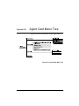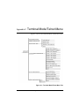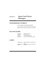
1
AGENT CARD
USER MANUAL
61200160L1#HS-1B
June 2000
Trademark Information
Open View is a registered trademark of Hewlett-Packard Company.
901 Explorer Boulevard
P.O. Box 140000
Huntsville, AL 35814-4000
(256) 963-8000
© 2000 ADTRAN, Inc.
All Rights Reserved.
Printed in U.S.A.
Notes provide additional useful information.
Cautions signify information that could prevent service interruption.
Warnings provide information that could prevent damage to the
equipment or endangerment to human life.
iii
FEDERAL COMMUNICATIONS COMMISSION RADIO FREQUENCY
INTERFERENCE STATEMENT
This equipment has been tested and found to comply with the limits for a Class A
digital device, pursuant to Part 15 of the FCC Rules. These limits are designed to
provide reasonable protection against harmful interference when the equipment
is operated in a commercial environment. This equipment generates, uses, and
can radiate radio frequency energy and, if not installed and used in accordance
with the instruction manual, may cause harmful interference to radio frequencies.
Operation of this equipment in a residential area is likely to cause harmful interference in which case the user will be required to correct the interference at his
own expense.
Shielded cables must be used with this unit to ensure compliance with Class A
FCC limits.
Change or modifications to this unit not expressly approved by
the party responsible for compliance could void the user’s authority to operate the equipment.
CANADIAN EMISSIONS REQUIREMENTS
This digital apparatus does not exceed the Class A limits for radio noise emissions
from digital apparatus as set out in the interference-causing equipment standard
entitled “Digital Apparatus," ICES-003 of the Department of Communications.
Cet appareil nuerique respecte les limites de bruits radioelectriques applicables
aux appareils numeriques de Class A prescrites dans la norme sur le materiel
brouilleur: "Appareils Numeriques," NMB-003 edictee par le ministre des Communications.
iv
CANADIAN EQUIPMENT LIMITATIONS
Notice: The Canadian Industry and Science Canada label identifies certified
equipment. This certification means that the equipment meets certain telecommunications network protective, operational, and safety requirements. The
Department does not guarantee the equipment will operate to the user’s satisfaction.
Before installing this equipment, users should ensure that it is permissible to be
connected to the facilities of the local telecommunications company. The equipment must also be installed using an acceptable methods of connection. In some
cases, the company’s inside wiring associated with a single line individual service may be extended by means of a certified connector assembly (telephone
extension cord). The customer should be aware that compliance with the above
limitations may not prevent degradation of service in some situations.
Repairs to certified equipment should be made by an authorized Canadian
maintenance facility designated by the supplier. Any repairs or alterations
made by the user to this equipment, or equipment malfunctions, may give the
telecommunications company cause to request the user to disconnect the equipment.
Users should ensure for their own protection that the electrical ground connections of the power utility, telephone lines and internal metallic water pipe system, if present, are connected together. This precaution may be particularly
important in rural areas.
Users should not attempt to make such connections themselves,
but should contract the appropriate electric inspection authority,
or an electrician, as appropriate.
The Load Number (LN) assigned to each terminal device denotes the percentage of the total load to be connected to a telephone loop which is used by the
device, to prevent overloading. The termination on a loop may consist of any
combination of devices subject only to the requirement that the total of the Load
Numbers of all devices does not exceed 100.
v
IMPORTANT SAFETY INFORMATION
SAVE THESE INSTRUCTIONS
When using your telephone equipment, please follow these basic safety precautions to reduce the risk of fire, electrical shock, or personal injury:
1. Do not use this product near water, such as near a bathtub, wash bowl,
kitchen sink, laundry tub, in a wet basement, or near a swimming pool.
2.
3.
4.
Avoid using a telephone (other than a cordless-type) during an electrical
storm. There is a remote risk of shock from lightning.
Do not use the telephone to report a gas leak in the vicinity of the leak.
Use only the power cord, power supply, and/or batteries indicated in the
manual. Do not dispose of batteries in a fire. They may explode. Check with
local codes for special disposal instructions.
WARRANTY AND CUSTOMER SERVICE
ADTRAN will replace or repair this product within five years from the date of
shipment if it does not meet its published specifications or fails while in service.
For detailed warranty, repair, and return information refer to the ADTRAN
Equipment Warranty and Repair and Return Policy Procedure.
Return Material Authorization (RMA) is required prior to returning equipment to
ADTRAN.
For service, RMA requests, or further information, contact one of the numbers
listed on the back page of this manual.
vi
LIMITED PRODUCT WARRANTY
ADTRAN warrants that for five (5) years from the date of shipment to Customer, all products manufactured by ADTRAN will be free from defects in
materials and workmanship. ADTRAN also warrants that products will conform to the applicable specifications and drawings for such products, as contained in the Product Manual or in ADTRAN's internal specifications and
drawings for such products (which may or may not be reflected in the Product
Manual). This warranty only applies if Customer gives ADTRAN written
notice of defects during the warranty period. Upon such notice, ADTRAN will,
at its option, either repair or replace the defective item. If ADTRAN is unable,
in a reasonable time, to repair or replace any equipment to a condition as warranted, Customer is entitled to a full refund of the purchase price upon return of
the equipment to ADTRAN. This warranty applies only to the original purchaser and is not transferable without ADTRAN's express written permission.
This warranty becomes null and void if Customer modifies or alters the equipment in any way, other than as specifically authorized by ADTRAN.
EXCEPT FOR THE LIMITEDWARRANTY DESCRIBED ABOVE, THE FOREGOING CONSTITUTES THE SOLE AND EXCLUSIVE REMEDY OF THE CUSTOMER AND THE EXCLUSIVE LIABILITY OF ADTRAN AND IS IN LIEU OF
ANY AND ALL OTHER WARRANTIES (EXPRESSED OR IMPLIED). ADTRAN SPECIFICALLY DISCLAIMS ALL OTHER WARRANTIES, INCLUDING
(WITHOUT LIMITATION), ALL WARRANTIES OF MERCHANTABILITY
AND FITNESS FOR A PARTICULAR PURPOSE. SOME STATES DO NOT
ALLOW THE EXCLUSION OF IMPLIEDWARRANTIES, SO THIS EXCLUSION MAY NOT APPLY TO CUSTOMER.
In no event will ADTRAN or its suppliers be liable to Customer for any incidental, special, punitive, exemplary or consequential damages experienced by
either Customer or a third party (including, but not limited to, loss of data or
information, loss of profits, or loss of use). ADTRAN is not liable for damages
for any cause whatsoever (whether based in contract, tort, or otherwise) in
excess of the amount paid for the item. Some states do not allow the limitation
or exclusion of liability for incidental or consequential damages, so the above
limitation or exclusion may not apply to Customer.
vii
viii
Table of Contents
List of Figures .......................................................................................................... xiii
List of Tables .............................................................................................................xv
Chapter 1. Introduction .......................................................................................... 1-1
AGent Card overview .............................................................................................. 1-1
Functional Description ............................................................................................ 1-2
Features................................................................................................................ 1-2
Agent Card Specifications................................................................................. 1-3
10-Base-T Interface ..................................................................................... 1-3
SLIP/EIA-232 Interface ............................................................................. 1-3
Chain-Out Interface ................................................................................... 1-4
Common ...................................................................................................... 1-4
MIB Support ................................................................................................ 1-4
Trap Support ............................................................................................... 1-4
Physical Description ................................................................................................. 1-5
Chapter 2. Installation ............................................................................................ 2-1
Unpack, Inspect, Power Up .................................................................................... 2-1
Receipt Inspection .............................................................................................. 2-1
ADTRAN Shipments Include........................................................................... 2-1
Provided by Customer ...................................................................................... 2-1
AGent Card Installation .......................................................................................... 2-2
Agent Card Placement....................................................................................... 2-2
Power Connection .............................................................................................. 2-3
Wiring .................................................................................................................. 2-3
Power-Up Testing and Initialization ..................................................................... 2-5
Successful Self Test............................................................................................. 2-5
Failed Self Test .................................................................................................... 2-5
Operation Alarms............................................................................................... 2-5
Chapter 3. Operation............................................................................................... 3-1
Overview ................................................................................................................... 3-1
Menu Structure ................................................................................................... 3-1
Menu Operation ................................................................................................. 3-1
61200160L1#HS-1
Agent Card User Manual
ix
Table of Contents
Agent Card Configuration ...................................................................................... 3-3
Front Panel Menus .................................................................................................... 3-4
Port Status............................................................................................................3-4
10BaseT ........................................................................................................ 3-4
TX .......................................................................................................... 3-4
RX .......................................................................................................... 3-4
LNK ....................................................................................................... 3-4
CPU ....................................................................................................... 3-4
EIA-232 ........................................................................................................ 3-5
Chain Port .................................................................................................... 3-5
Flash Download .......................................................................................... 3-5
Port Configuration (PORT CONFIG) ..............................................................3-5
IP Interface ........................................................................................... 3-5
IP Address ............................................................................................ 3-6
Subnet Mask ......................................................................................... 3-6
Default Router ..................................................................................... 3-6
RS-232 Rate .......................................................................................... 3-6
RS-232 Flow Control ........................................................................... 3-6
Port Utility (PORT UTIL) .................................................................................. 3-6
SW REVISION ..................................................................................... 3-7
ENET ADDRESS ................................................................................. 3-7
telnet/terminal menus ............................................................................................. 3-7
Main Menu .......................................................................................................... 3-7
Host Menu Access ...................................................................................... 3-8
Remote Menu Access ................................................................................. 3-8
Unit Access Table ....................................................................................... 3-8
Add New Unit ..................................................................................... 3-9
Modify Unit ......................................................................................... 3-9
Delete Unit ........................................................................................... 3-9
Default Unit Passcode ...................................................................... 3-10
OK ....................................................................................................... 3-10
Management Configuration ................................................................... 3-10
SNMP Read Community ................................................................. 3-10
SNMP Read/Write Community ..................................................... 3-10
SNMP Trap Community .................................................................. 3-11
Host 1 Trap IP Address .................................................................... 3-11
Host 2 Trap IP Address .................................................................... 3-11
Host 3 Trap IP Address .................................................................... 3-11
Host 4 Trap IP Address .................................................................... 3-11
System Name ..................................................................................... 3-11
System Contact .................................................................................. 3-11
System Location ................................................................................ 3-11
x
Agent Card User Manual
61200160L1#HS-1
Table of Contents
Auth. Fail Traps Sent ....................................................................... 3-12
Poll Link Status Traps Sent .............................................................. 3-12
Ping IP Hosts ..................................................................................... 3-12
Exit ...................................................................................................... 3-12
TCP/IP Configuration ............................................................................. 3-12
TCP/IP Interface ............................................................................... 3-12
Agent IP Address .............................................................................. 3-12
Agent SUBNET Mask ....................................................................... 3-12
Default IP Router .............................................................................. 3-12
Telnet/Terminal Timeout ................................................................ 3-13
Telnet/Terminal Password ............................................................. 3-13
Exit ...................................................................................................... 3-13
RS-232 Configuration .............................................................................. 3-13
RS-232 Rate ........................................................................................ 3-13
RS-232 Flow Control ......................................................................... 3-13
Quit Session .............................................................................................. 3-13
Flash Download................................................................................................ 3-13
Appendix A. SNMP .............................................................................................. A-1
Appendix B. Agent Card Menu Tree .................................................................. B-1
Appendix C. Terminal Mode/Telnet Menu ..................................................... C-1
Appendix D. Agent Card Failure Messages ..................................................... D-1
Appendix E. Acronyms and Abbreviations ...................................................... E-1
61200160L1#HS-1
Agent Card User Manual
xi
Table of Contents
xii
Agent Card User Manual
61200160L1#HS-1
List of Figures
Figure 1-1. Typical Agent Card Application......................................................... 1-2
Figure 1-2. Agent Option Module.......................................................................... 1-5
Figure 2-1. Installing the Agent Card .................................................................... 2-2
Figure 3-1. TSU 100 Main Menu............................................................................. 3-2
Figure 3-2. 10BaseT Status Display ........................................................................ 3-4
Figure 3-3. Telnet/Terminal Main Menu............................................................... 3-7
Figure 3-4. Unit Access Table .................................................................................. 3-9
Figure B-1. Agent Card Menu Tree ........................................................................B-1
Figure C-1. Terminal Mode/Telnet Menu Tree ................................................... C-1
61200160L1#HS-1
Agent Card User Manual
xiii
List of Figures
xiv
Agent Card User Manual
61200160L1#HS-1
List of Tables
Table 2-1. 10-Base-T Ethernet.................................................................................. 2-3
Table 2-2. Pinout for EIA-232 Connector ............................................................. 2-4
Table 2-3. Pinout for Chain-Out Connector.......................................................... 2-4
61200160L1#HS-1
Agent Card User Manual
xv
List of Tables
xvi
Agent Card User Manual
61200160L1#HS-1
Chapter 1
Introduction
AGENT CARD OVERVIEW
The embedded Agent Card is a standard TSU product option card that allows Simple Network Management Protocol (SNMP), telnet, and T-Watch over TCP/IP
management of the TSU/HSU in which the card is installed as well as up to 16 additional devices that are daisy
chained to the Agent Card. The Agent Card also forwards
traps received from chained devices as SNMP traps to
network management stations (NMS). See the appendix
SNMP for more information. The Agent Card is connected to a TCP/IP network using either the 10-Base-T Ethernet or EIA-232 serial line internet protocol (SLIP) interface
on the rear panel of the option module. Figure 1-1 on
page 1-2 shows a typical Agent Card application.
Each of the Agent Cards in this application must be assigned a fixed IP address. The unit ID of each TSU is appended to the SNMP community name to provide unique
identification of chained units.
61200160L1#HS-1
Agent Card User Manual
1-1
Chapter 1. Introduction
TSU100
A
ENTER
REMOTE
B
1
TEST
*
HOME
0
CSU
ALARM
OK TEST
B
1
ALARM
COPY
*
HOME
0
ALARM
CSU
OK TEST
B
1
ALARM
COPY
*
3
E
5
ALARM
8
7
TEST
ALARM
C
2
D
4
REMOTE
OK
ERROR
TSU100
A
ENTER
CANCEL
DSU
F
6
CLEAR
9
SHIFT
#
MODULE
OK TEST
REMOTE
3
E
5
ALARM
8
7
TEST
ALARM
C
2
D
4
REMOTE
OK
ERROR
TSU100
A
ENTER
CANCEL
DSU
F
6
CLEAR
9
SHIFT
#
MODULE
ALARM
OK TEST
REMOTE
3
E
5
ALARM
8
7
OK
C
2
D
4
REMOTE
COPY
CANCEL
DSU
HOME
0
F
6
CLEAR
9
SHIFT
#
MODULE
OK TEST
ALARM
CSU
OK TEST
ERROR
ALARM
T1
T1
TSU100
A
ENTER
REMOTE
B
1
TEST
ALARM
COPY
*
HOME
0
ALARM
CSU
OK TEST
B
1
TEST
ALARM
COPY
*
HOME
0
ALARM
CSU
OK TEST
2
3
E
F
4
5
ALARM
8
7
TEST
ALARM
COPY
*
HOME
0
ERROR
ALARM
C
1
D
REMOTE
CANCEL
OK
F
6
CLEAR
9
SHIFT
#
MODULE
OK TEST
DSU
3
E
5
ALARM
8
7
OK
ALARM
C
2
D
4
REMOTE
CANCEL
DSU
B
ERROR
TSU100
A
ENTER
REMOTE
TSU100
A
ENTER
F
6
CLEAR
9
SHIFT
#
MODULE
OK TEST
REMOTE
3
E
5
ALARM
8
7
OK
C
2
D
4
REMOTE
CANCEL
DSU
6
CLEAR
9
SHIFT
#
MODULE
OK TEST
ALARM
CSU
OK TEST
ERROR
ALARM
Figure 1-1. Typical Agent Card Application
FUNCTIONAL DESCRIPTION
The Agent Card is designed to fit in the option slot of a
TSU 100/120/600 or an HSU 100/120/600 and is subject
to their operation and control. The Agent Card is configured using the front panel menus and the telnet/terminal
interface.
Features
The Agent Card has the following features:
1-2
•
10-Base-T interface for local area network (LAN) connection to network management station.
•
SLIP EIA-232 interface for serial connection to network management station.
•
Proxy chain output for connection to other TSU devices. This permits one Agent Card to serve up to 16 ex-
Agent Card User Manual
61200160L1#HS-1
Chapter 1. Introduction
ternal devices (other TSU 100/120/600s, ISU 512s, or
standalone TSUs).
•
Flash ROM upgrade using EIA-232 port.
•
For TSU product management tasks, support for SNMP, telnet, and T-Watch over TCP/IP.
•
Ability to configure the Agent Card with a VT 100 terminal attached to the EIA-232 interface.
•
For hardware to IP address mapping, support for Address Resolution Protocol (ARP).
•
For basic IP error reporting, support for Internet Control Message Protocol (ICMP).
•
Support for packet internet groper (PING).
Agent Card Specifications
The Agent Card conforms to the following specifications:
10-Base-T Interface
Interface
Complies with IEEE 802.3
Rate
10 megabits per second (Mbps)
Connector
RJ-45 (AT&T 258A) connector
Indicators
Transmit, receive, link status, central processing unit (CPU) access (via front panel)
Receiver
Accepts signal > 300 millivolt (mV)
Protocols
Network: IP
Transport: TCP, UDP
Service: SNMP, Telnet, ICMP, ARP,
PING, T-Watch
SLIP/EIA-232 Interface
61200160L1#HS-1
Interface
EIA-232 physical interface
Rates
1200, 2400, 4800, 9600, 19200, 38400
bits per second (bps)
Signals
RD, TD, CTS, RTS, DCD, RI, DTR
Pinout
DCE
Agent Card User Manual
1-3
Chapter 1. Introduction
Connector
RJ-45 connector
Protocols
Network: IP
Transport: TCP, UDP
Service: SNMP, Telnet, ICMP, ARP,
PING, T-Watch
Chain-Out Interface
Interface
EIA-232 physical interface (TSU-X00
chain-out interface)
Rates
1200, 2400, 9600, 19200, 38400 bps
Connector
RJ-45 (AT&T 258A) connector
Signals
RXD, TXD
Pinout
DTE
Connector
RJ-45
Protocols
Link: ADLP
Service: T-Watch, ATEL
Common
Mechanical
Mechanically compatible with option slot
of TSU-X00
Environmental
Operating temperature 0 to 45 oC
Tests
Extensive self tests
MIB Support
MIB II
RFC 1406 (DS1 MIB)
ADTRAN DS1 Extension Management Information Bases (MIBs)
All TSU-X00 enterprise MIBs
Trap Support
ADTRAN TSU-X00 enterprise traps (including option modules)
MIB II SNMP traps
1-4
Agent Card User Manual
61200160L1#HS-1
Chapter 1. Introduction
PHYSICAL DESCRIPTION
The Agent Card is an option module which plugs into the
option slot in the rear of the TSU/HSU. See Figure 1-2.
Figure 1-2. Agent Option Module
The Agent Card rear panel includes a plastic plug over a
cutout for a V.35 connector. This allows a V.35 Nx56/64
interface plug-on card to be added to the Agent Card.
The PORT X.1 identification on the rear panel is linked to
the port numbering philosophy of the TSU/HSU product
family. The X represents the slot number, and the .1 indicates the port number. For the TSU 100 application, there
is only one option slot. Therefore, the port designation for
the Agent port is 1.1. If added, the Nx56/64 port designation is 1.2. These port numbers appear in the front panel
LCD menu displays.
61200160L1#HS-1
Agent Card User Manual
1-5
Chapter 1. Introduction
1-6
Agent Card User Manual
61200160L1#HS-1
Installation
Chapter 2
UNPACK, INSPECT, POWER UP
Receipt Inspection
Carefully inspect the Agent Card for any shipping damage. If damage is suspected, file a claim immediately with
the carrier and contact ADTRAN Customer and Product
Service. If possible, keep the original shipping container
for use in shipping the Agent Card for repair or for verification of damage during shipment.
ADTRAN Shipments Include
The following items are included in ADTRAN shipments
of the TSU IQ Rackmount:
•
Agent Card
•
Agent/TSU jumper cable
•
EIA-232 DB-25 to RJ-45 adapter
•
User Manual (to be inserted into main TSU/HSU User
Manual)
Provided by Customer
The customer must provide the following cables:
61200160L1#HS-1
•
Cable for connection to 10-Base-T LAN (RJ-45)
•
Cable for connection to router or terminal server SLIP
port (not required if 10-Base-T port is used)
Agent Card User Manual
2-1
Chapter 2. Installation
AGENT CARD INSTALLATION
Instructions on installing the Agent Card in the TSU 100/600 also apply
to the TSU 120 and the HSU 100/120/600.
Turn the units off where installing the Agent Card.
Agent Card Placement
Figure 2-1 represents the action required for proper placement of the Agent Card.
1.
Remove cover plate from the rear panel.
2.
Slide option module into the rear panel until it is
positioned firmly against the front.
3.
Fasten thumb-screws at both edges of option module.
4.
Install Agent/TSU jumper cable between the Chainout connector on the Agent Card and the Chain-in
connector on the TSU.
5.
Install additional jumpers between the unit chain-in
and chain-out ports to manage other units by the
Agent Card.
Figure 2-1. Installing the Agent Card
2-2
Agent Card User Manual
61200160L1#HS-1
Chapter 2. Installation
Power Connection
Each Agent Card derives power from the base of the unit.
Power to the unit is supplied by a captive eight foot power cord.
Wiring
The Agent Card has three RJ-45 style connectors:
•
10-Base-T for connection to an Ethernet LAN
•
EIA-232 for connection to SLIP, VT 100 style terminal, or Flash Download via AFLASH
•
Chain-out for connection to the TSU(s) that it is serving
The required wiring connections are:
Connector Type (USOC) = RJ-45
Part number = AMP # 555164-1
Table 2-1. 10-Base-T Ethernet
To NIC
10BT
61200160L1#HS-1
Agent Card User Manual
Pin 1
TX1
Pin 2
TX2
Pin 3
RX1
Pin 6
RX2
2-3
Chapter 2. Installation
Table 2-2. Pinout for EIA-232 Connector
EIA-232
Pin
Name
Description
1
GND
Signal Ground
2
RTS
Request to Send (Input)
3
TD
Transmit Data (Input)
4
DTR
Data Terminal Ready
(Output)
5
RD
Receive Data (Output)
6
CD
Carrier Detect (Input)
7
RI
Ring Indicate (Input)
8
CTS
Clear to Send (Output)
This port is wired as a DCE interface; however, pins 4, 6, and 7 (DTR,
CD, RI) are wired to allow connection to an external DCE using a
special crossover RJ-45 to DB-25 converter (the standard RJ-45 to DB25 converter supplied with the Agent Card does not connect pins 4, 6,
and 7).
Table 2-3. Pinout for Chain-Out Connector
CHAIN-OUT
2-4
Pin
Name
Description
1
Ground
Signal Ground
3
TD
Transmit Data
(Input)
5
RD
Receive Data
(Output)
Agent Card User Manual
61200160L1#HS-1
Chapter 2. Installation
POWER-UP TESTING AND INITIALIZATION
The Agent Card executes a self test during the power-up
sequence, as described in the TSU 100/600 User Manuals.
No initialization input is required. Any previously configured setting for the Agent Card is restored automatically upon power-up.
Successful Self Test
The green OK LED, located with the Module LEDs on the
front panel, illuminates when a successful self test is completed and the configuration is successfully restored. See
Front Panel Operation, TSU 100/600 User Manual.
Failed Self Test
The LCD displays a message during power up if the
Agent Card fails one or more of the self tests. See TSU
100/600 User Manual. The appendix TSU 100/600 System
Messages identifies specific Agent Card failures in the
alarm listings.
Operation Alarms
When an alarm condition is detected, the red ALARM
LED on the front panel illuminates.
61200160L1#HS-1
Agent Card User Manual
2-5
Chapter 2. Installation
2-6
Agent Card User Manual
61200160L1#HS-1
Chapter 3
Operation
OVERVIEW
The Agent Card is controlled as part of the TSU 100/600
using the same methods as described in the TSU 100/600
User Manual.
See the TSU 100/600 User Manual for descriptions of front
panel indicators and buttons.
Instructions on installing the Agent Card in the TSU 100/600 also apply
to the TSU 120 and the HSU 100/120/600.
Menu Structure
When an option card is installed in the TSU 100/600, the
unit adds it to the list of selectable options under the Port
menu items. These menu items are shaded in the limited
overview of the TSU 100 menu shown in Figure 3-1. The
appendix, TSU 100 Complete Menu, of the TSU 100 User
Manual shows a complete menu diagram.
Menu Operation
An option module must be selected from the listing in one
of the Port menu options before its menus are applicable.
With the cursor on one of the Port menu items, press Enter
61200160L1#HS-1
Agent Card User Manual
3-1
Chapter 3. Operation
to display a list of the currently installed option modules.
To activate menus for the Agent Card, scroll through the
list to display X.1 AGENT and press Enter.
Once the option module is selected, the Agent menus appear as a subset of, and operate the same as, menus for the
TSU 100/600. With the cursor on one of the TSU 100/600
four Main menu choices, press Enter or a menu number to
display the first two submenu items.
Use the up and down arrows to place the cursor on the desired item and press Enter to display the first two submenu choices.
Figure 3-1. TSU 100 Main Menu
3-2
Agent Card User Manual
61200160L1#HS-1
Chapter 3. Operation
AGENT CARD CONFIGURATION
After installation, the Agent Card must be properly configured via the TSU/HSU front panel, telnet session, EIA232 terminal session, or SNMP MIB browser. Note that
certain configuration information such as SNMP community names, telnet password, and Device Configuration
Tables cannot be viewed or changed from the front panel
menus. These items can only be accessed from telnet/terminal menus or the SNMP MIB browser. Also, IP address, default gateway, and subnet mask must be set to
their proper values from the front panel or EIA-232 terminal menus before further configuration via telnet or
SNMP is possible.
A non-zero passcode must be set on all TSU/HSU units accessed by the
Agent Card, including the controller the card is installed in.
A typical application for SNMP access over a 10BaseT
LAN would require the following configuration steps:
61200160L1#HS-1
1.
Set TCP/IP interface to 10BaseT via the front panel.
This is the default setting.
2.
Configure IP address, default gateway, and subnet
mask via the TSU/HSU front panel menus.
3.
From a personal computer (PC) or workstation anywhere on the TCP/IP network to which the Agent
Card is connected, telnet to the Agent Card IP
address.
4.
Set telnet password, community names, trap destination addresses, etc. from telnet menus.
Agent Card User Manual
3-3
Chapter 3. Operation
FRONT PANEL MENUS
Port Status
Port Status, a submenu of TSU/HSU Main menu item Status, displays error information about the Agent Card interfaces. An asterisk (*) indicates an item is active (see
Figure 3-2). Agent Card Menu Tree on page B-1 shows the
complete menu.
Figure 3-2. 10BaseT Status Display
10BaseT
TX
Indicates that data is being transmitted from the 10BaseT
port.
RX
Indicates that data is being received by the 10BaseT port.
LNK
Indicates that current status of the 10BaseT link integrity
test (should always be on when the unit is connected to a
functional 10BaseT hub).
CPU
Active when the Agent Card CPU is accessing the
10BaseT interface.
3-4
Agent Card User Manual
61200160L1#HS-1
Chapter 3. Operation
EIA-232
TD
Transmit data (from DTE)
RD
Receive data (to DTE)
RS
Request to send
CS
Clear to send
CD
Carrier detect
TD
Transmit data (to host device)
RD
Receive data (from host device)
Chain Port
Flash Download
Displays percentage download complete. In non-flash
download mode, this option is not available.
Port Configuration (PORT CONFIG)
Port Configuration, a submenu of TSU/HSU Main menu
item Configuration, is used to configure the TSU Agent
Card.
IP Interface
(10BaseT ETHER, SLIP; defaults to 10BaseT ETHER)
Selects the TCP/IP physical interface; 10BaseT Ethernet
or SLIP using the EIA-232 serial port.
If this option is set to SLIP, the EIA-232 port may not be used as a
terminal interface.
61200160L1#HS-1
Agent Card User Manual
3-5
Chapter 3. Operation
IP Address
(0.0.0.0 - 255.255.255.255; defaults to 0.0.0.0)
This is the IP address that uniquely identifies the Agent
Card on a TCP/IP network. This address is composed of
four decimal numbers, each in the range of 0 to 255, separated by periods. This value is used for either the
10BaseT Ethernet or SLIP interface, depending on the IP
interface setting.
Subnet Mask
(0.0.0.0 - 255.255.255.255; defaults to 255.255.255.0)
Defines which part of a destination IP address is the Network number. Used along with the Agent Card IP
address to determine which nodes must be reached
through the default IP Gateway. This value is set to
0.0.0.0 when the IP interface option is set to SLIP.
Default Router
(0.0.0.0 - 255.255.255.255; defaults to 0.0.0.0)
All IP packets destined for nodes not on the Agent Card's
local network are not forwarded through this IP address.
Normally, this address defines a router connected to the
Agent Card's local network. This value is ignored when
the IP interface is set to SLIP.
RS-232 Rate
(1200, 2400, 4800, 9600, 19200, 38400; defaults to 9600)
Selects the baud rate of EIA-232 port.
RS-232 Flow Control
(NONE, HARDWARE; defaults to NONE)
Selects the flow control method for the EIA-232 port.
Port Utility (PORT UTIL)
Port Utility, a submenu of the TSU/HSU Main menu item
Utilities (UTIL), displays the current software revision
and Ethernet MAC address of the Agent Card. Also,
Flash Download is initiated from this menu.
3-6
Agent Card User Manual
61200160L1#HS-1
Chapter 3. Operation
SW REVISION
Displays the Agent Card software revision.
ENET ADDRESS
Displays the Ethernet MAC address for the 10BaseT port
on the Agent Card.
TELNET/TERMINAL MENUS
Main Menu
The telnet/terminal Main menu is the first menu displayed after the telnet/terminal session is established (see
Figure 3-3). The default telnet/terminal password is
ADTRAN. Terminal Mode/Telnet Menu on page C-1 shows
the complete menu tree.
Only one telnet/terminal session may be active at a time.
Figure 3-3. Telnet/Terminal Main Menu
61200160L1#HS-1
Agent Card User Manual
3-7
Chapter 3. Operation
Host Menu Access
When selected, displays the Main menu for the TSU/HSU
in which the Agent Card is installed. Once in terminal
mode, CTRL + X terminates the telnet session and returns
to the Agent Card Main menu.
Remote Menu Access
Displays telnet menus for a remote device (may be another TSU/HSU or any other ADTRAN product that supports telnet via its EIA-232 chain port). After selecting
this option, the user may choose to connect to a device entered in the Unit Access Table or enter a unit ID for a unit
not in the Unit Access Table. CTRL + X terminates the session and return to the Agent Card Main menu.
Unit Access Table
This menu is used to edit/create the Unit Access Table.
This table is used to store the Unit ID, Passcode, and Unit
Type for units connected via chain ports or connected remotely to the TSU/HSU in which the Agent Card is installed (see Figure 3-4). An entry in the table is only
required to support SNMP MIB access or polling. For
MIB access, an entry is required only if the unit's passcode
is not the same as the Default Unit Passcode, or the unit is
a single port TSU Standalone.
It is not necessary to have an entry in this table for a remote unit in order
to telnet to it or forward SNMP traps from it. In the telnet case, the
Remote Menu Access menu is selected from the Main menu and a unit
ID is entered which may or may not be in the Unit Access Table. Also, it
is not necessary to add an entry in this table for the TSU/HSU in which
the Agent Card is installed. This unit automatically appears as the first
entry in the table and is identified as the HOST.
Units accessed via T-Watch over TCP/IP uses the unit ID
and passcode set by T-Watch running on the PC.
3-8
Agent Card User Manual
61200160L1#HS-1
Chapter 3. Operation
Figure 3-4. Unit Access Table
Add New Unit
Adds a new device to the table. The user must enter a
device unit ID, passcode, unit type, and polled flag. Unit
type can be Standard (which supports any TSU/HSU
Multiplexer and the ISU 512) or TSU Standalone (a single
port TSU with no option card slot). A passcode of 0 to
9999 for each device or DEFAULT may be selected, which
results in the default passcode being used (defined as
0022 in Figure 3-4). Traps are normally sent from the unit
in alarm to the Agent Card. For units in the Unit Access
Table that are not chained directly to the Agent Card but
are managed over Inband or the FDL, traps are not automatically forwarded. Polling must be enabled on the
Agent Card for these units in order to receive Traps on
the NMS. The Agent Card can be configured to poll
selected units for traps by enabling the polled option
when adding or modifying a unit entry.
Modify Unit
Allows unit ID, passcode, device type , and polled flag to
be changed for an existing entry in the table.
Delete Unit
Deletes an entry in the table.
61200160L1#HS-1
Agent Card User Manual
3-9
Chapter 3. Operation
Default Unit Passcode
Sets the default passcode for all devices in the table that
have passcodes set to DEFAULT, or for any unit not listed
in the table.
OK
Returns to the Configure Agent menu.
Management Configuration
This menu sets management information, such as SNMP
community names and trap destination addresses.
SNMP Read Community
SNMP Read Community Name defaults to public.
NMSs using this community name have Read access for
all supported MIB objects but do not have the ability to
change MIB objects. This value must be set to the same
value on both the Agent Card and the NMS (OpenView®, etc.) in order for the NMS to have Read access to
MIBs supported by the Agent Card. This value must be a
text string of 16 characters or less.
SNMP Read/Write Community
SNMP NMS using this community name have full read/
write access to all supported MIB objects (defaults to private). This setting must be the same value on both the
Agent Card and the NMS in order for the NMS to have
read/write access to MIBS supported by the Agent Card.
This value must be a text string that is 16 characters or
less.
To access other units external to the Agent Card-equipped TSU/HSU
using an SNMP MIB browser, append a period and the unit ID of the
external device to the Read Only and Read/Write commuity name used in
the MIB Browser, for example public.4. SNMP on page A-1 gives more
information.
3-10
Agent Card User Manual
61200160L1#HS-1
Chapter 3. Operation
SNMP Trap Community
This community name is used for all SNMP traps forwarded by the Agent Card. Traps received from daisy
chained units have a period and the unit ID appended to
the trap community name.
Host 1 Trap IP Address
The first of four entries for SNMP trap destination
addresses. The Agent Card forwards all SNMP traps to
the IP address specified in this entry. If the address is set
to the default value of 0.0.0.0, no traps are forwarded for
this particular value.
Host 2 Trap IP Address
Defaults to 0.0.0.0. Second destination address for SNMP
traps.
Host 3 Trap IP Address
Defaults to 0.0.0.0. Third destination address for SNMP
traps.
Host 4 Trap IP Address
Defaults to 0.0.0.0. Fourth destination address for SNMP
traps.
System Name
A text string that can uniquely identify an SNMP managed node.
System Contact
A text string containing the name, phone number, etc. of
the individual responsible for maintaining an SNMP
managed node.
System Location
A text string describing the physical location of an SNMP
managed node (for example, SECOND FLOOR PBX
ROOM).
61200160L1#HS-1
Agent Card User Manual
3-11
Chapter 3. Operation
Auth. Fail Traps Sent
(DISABLED, ENABLED: defaults to DISABLED)
When enabled, the Agent Card issues an SNMP trap
when any SNMP request is received with an invalid community name. Can be used for security purposes.
Poll Link Status Traps Sent
(DISABLED, ENABLED, defaults to DISABLED)
When enabled, the Agent Card sends an SNMP trap
whenever a device configured to be polled fails to
respond. When the device begins responding to polls, a
poll link up trap is sent. The format of the traps are
defined in the agent MIB.
Ping IP Hosts
Allows the user to Ping a specific IP address.
Exit
Returns to the Agent Card Main menu.
TCP/IP Configuration
Used to configure TCP/IP.
TCP/IP Interface
See Front Panel Menus on page 3-4. (Available as a Read
Only option from telnet.)
Agent IP Address
See Front Panel Menus on page 3-4. (Available as a Read
Only option from telnet).
Agent SUBNET Mask
See Front Panel Menus on page 3-4. (Available as a Read
Only option from telnet).
Default IP Router
See Front Panel Menus on page 3-4. (Available as a Read
Only option from telnet).
3-12
Agent Card User Manual
61200160L1#HS-1
Chapter 3. Operation
Telnet/Terminal Timeout
The Agent Card terminates a telnet or terminal session if
no activity is detected for this length of time. Only one
telnet or terminal session may be active at one time. This
timeout prevents an unattended session from blocking
interactive access to the agent. The default value is five
minutes.
Telnet/Terminal Password
This option allows modification of the password
required for entry into a telnet or terminal session. The
default value is ADTRAN.
Exit
Returns to the Agent Card Main menu.
RS-232 Configuration
RS-232 Rate
Selects the EIA-232 port rate (see Front Panel Menus on
page 3-4). This is a Read Only option from telnet and terminal mode.
RS-232 Flow Control
Selects EIA-232 handshake mode (see Front Panel Menus
on page 3-4).
Quit Session
Terminates the telnet/terminal session.
Flash Download
The Agent Card uses flash memory that allows software
updates via the EIA-232 port. The following steps outline
the procedure that must be used to update the Flash on
the Agent Card:
1.
61200160L1#HS-1
Use the DB-25 to RJ-45 adaptor that is shipped with
the Agent Card to connect the EIA-232 port on the
Agent Card to one of the COM ports on a PC capable
Agent Card User Manual
3-13
Chapter 3. Operation
of running AFLASH (the ADTRAN Windows-based
Flash Download utility).
The latest version of AFLASH, along with the latest revision of the Agent
Card firmware, may be obtained from the ADTRAN World Wide Web
homepage at http://www.adtran.com.
2.
Using the TSU/HSU front panel, set the desired EIA232 baud rate for the Agent Card. To allow the shortest possible download time, 38400 is recommended.
3.
Launch AFLASH on the PC and follow the on-screen
instructions. AFLASH should be set to use the COM
port that is connected to the Agent Card. The baud
rate on AFLASH should be set to match the same
rate that the Agent Card EIA-232 port rate is set to in
Step 2.
4.
Press any front panel key at this point to return to the
TSU/HSU menus. The progress of the download
can be monitored by selecting FLASH DOWNLOAD under the Port Status menu for the Agent
Card.
5.
Once the Flash Download has completed, the Agent
Card removes the FLASH DOWNLOAD alarm and
the front panel display should read FLASH DOWNLOAD SUCCESSFUL. Press any front panel key to
return to the TSU/HSU menus.
If power is lost during an Agent Card Flash Download
session, the AGENT CARD FLASH DOWNLOAD
MODE message is displayed when power is restored.
Agent Card Failure Messages on page D-1 lists all error messages. In this situation, AFLASH may be restarted and
the download session resumed.
3-14
Agent Card User Manual
61200160L1#HS-1
Appendix A
SNMP
UNDERSTANDING SNMP
As local area network (LAN) environments became standardized over the past ten years, multi-vendor equipment grew with competition. It became necessary to
manage the various vendor equipment from a single control console. Thus, the SNMP emerged as the standard for
managing commercial TCP/IP networks.
The term SNMP broadly refers to the message protocols
used to exchange information between the network and
the managed devices, as well as to the structure of network management databases.
Basic Components
SNMP has three basic components: Network Manager,
Alert, and MIB.
Network Manager
This is a control program that collects, controls, and presents data pertinent to the operation of the network devices. It resides on a network management station.
61200160L1#HS-1
Agent Card User Manual
A-1
Appendix A. SNMP
Agent
This is a control program that responds to queries and
commands from the network manager and returns requested information or invokes configuration changes
initiated by the manager. It resides in each network device.
MIB
This is an index to the organized data within a network
device. It defines the operating parameters that can be
controlled or monitored. When requesting the network
manager to retrieve or modify a particular piece of information about a network device, the network manager
transmits the request to that network device. The agent in
that device interprets the incoming request, performs the
requested task, and sends its response to the network
manager. The network manager collects all the data from
the various network devices and presents it in a consistent form.
Commands
Using SNMP Version 1, the network manager can issue
three types of commands: GetRequest, GetNextRequest,
and SetRequest.
GetRequest
This command retrieves a single item or the first in a series from a network device.
GetNextRequest
This command retrieves the next item in a series from a
network device.
SetRequest
This command writes information to a network device.
A-2
Agent Card User Manual
61200160L1#HS-1
Appendix A. SNMP
Message
The network device issues two types of messages: GetResponse and Trap.
GetResponse
This message is the response to a network manager
GetRequest or GetNextRequest command.
Trap
This is an unsolicited message issued by a network device
to report an operational anomaly or an alarm condition to
the network manager.
These messages are typically encased within informational packets and transported over the LAN or WAN (wide
area network).
AGENT CARD SNMP ACCESS
By default, SNMP MIB Browser access to the Agent
Card's IP address with the configured community names
accesses the host TSU/HSU the card is installed in. The
Agent Card can also act as an SNMP proxy agent for external units. To access MIB variables on externally
chained devices, append a period and the Unit ID of the
device to the Read and Read/Write community names.
For example, if the Read community name configured in
the Agent is public, specifying "public.3" as the community name in the SNMP MIB Browser allows reading
SNMP MIB variables from externally chained unit 3.
If the external unit's passcode is not the default, an entry
must be added to the Unit Access Table for SNMP MIB access. Figure 3-4 on page 3-9 gives a description of this operation. However, SNMP traps for the unit can be
forwarded without the entry.
61200160L1#HS-1
Agent Card User Manual
A-3
Appendix A. SNMP
SNMP TRAP CONFIGURATION
Traps received by the Agent Card from external units and
the host unit are converted into SNMP traps and forwarded to the configured NMS. The source of the trap is
uniquely identified at the NMS by a combination of the
IP address of the Agent Card, and the Unit ID of the sending device. The Unit ID is present in the trap packet appended to the end of the trap community packet name,
for example public.4. It is also included as an Octet String
variable (adProdPhysAddress) in the trap packet as defined in the individual product MIBs. The latest versions
of the product MIBs by default display the appended trap
community name in their descriptions.
Typical steps required for Management Station trap configuration are loading the device specific MIBs. and loading or creating device specific Trap Definition Files. The
current product MIBs contain keywords embedded in
comments that can be used by some network management platforms to automatically generate Trap Definitions. Otherwise, the descriptions may be used as a
template for Trap Definitions.
If individual option card port and slot identification is required, it is present in the four byte adProdPhysAddress
field of the trap packet. The first two bytes are the Unit ID
of the base controller (least significant byte first). The next
two bytes are port and slot number. This field is the second object identifier in all traps sent from TSU/HSU
products. For traps from the ISU 512, the Unit ID is the
first object identifier. See the product MIBs for more information
Definitions for Poll Link Up/Down traps are included in
the Agent Card MIB file: TSUAGENT.MIB.
A-4
Agent Card User Manual
61200160L1#HS-1
Appendix A. SNMP
SNMP MIB BROWSER CONFIGURATION
The following are typical steps required to configure Network Manager MIB variable access through the Agent
Card:
1.
Load the desired product MIBs on the network management station. If, for example, the administrator is
managing TSU 100 and ISU 512 devices, load TSU
100.MIB, ISU512.MIB, and RFC1406.MIB.
2.
Create device entries in the NMS database for all
units that are to be managed through the Agent
Card. The host unit should be configured as the
Proxy agent for the external units. The IP address or
host name used for the proxy designation is that of
the Agent Card.
3.
Set community names in the devices entries for
external units to the Agent Card's community name
with the device Unit ID appended as defined in
Agent Card SNMP Access on page A-3.
4.
Set the device timeout for all device entries in the
NMS device database to five seconds, including the
host unit.
SNMP MIB FILES
The Agent Card supports several standard MIBs including MIB-II (RFC-1213), the DS1 T1/E1 MIB (RFC-1406),
and the Ethernet MIB (RFC-1643). It also supports several
ADTRAN enterprise specific MIBs including the ADTRAN Product MIB (ADTRAN.MIB), the ADTRAN DS1
extensions MIB (ADS1.MIB), and all TSU/HSU Enterprise MIBs, such as TSU 100.MIB.
The standard MIB files are usually included with most
SNMP network management software. The latest version
of the ADTRAN enterprise specific MIBs are available
from the ADTRAN anonymous ftp site (ftp.adtran.com),
or by dial-up from the BBS (205 -971-8169).
61200160L1#HS-1
Agent Card User Manual
A-5
Appendix A. SNMP
A-6
Agent Card User Manual
61200160L1#HS-1
Appendix B
Agent Card Menu Tree
Figure B-1 shows the menu tree for the Agent Card.
Figure B-1. Agent Card Menu Tree
61200160L1#HS-1
Agent Card User Manual
B-1
Appendix B. Agent Card Menu Tree
B-2
Agent Card User Manual
61200160L1#HS-1
Appendix C
Terminal Mode/Telnet Menu
Figure C-1 shows the Terminal Mode/Telnet menu tree.
Figure C-1. Terminal Mode/Telnet Menu Tree
61200160L1#HS-1
Agent Card User Manual
C-1
Appendix C. Terminal Mode/Telnet Menu
C-2
Agent Card User Manual
61200160L1#HS-1
Appendix D
Agent Card Failure
Messages
FAILURE MESSAGE AT POWER UP
AGENT CARD FLASH DOWNLOAD MODE
Agent Card needs to be Flash Downloaded. This message
indicates a blank or partially programmed Flash Memory.
SELF TEST FAILURES
EPROM CS
EPROM checksum error
RAM ERR
Dynamic RAM error
E2 ERR
Cannot program EEPROM
ENET ERR
CPU cannot access ethernet controller
10BASET LINK
Indicates 10BaseT Link integrity test has
failed
FLASH DOWNLOAD
Active when Agent Card is in Flash Download mode
ALARMS
61200160L1#HS-1
Agent Card User Manual
D-1
Appendix D. Agent Card Failure Messages
D-2
Agent Card User Manual
61200160L1#HS-1
Appendix E
Acronyms and Abbreviations
ADLP ...............................ADTRAN data link protocol
ARP ..................................address resolution protocol
ATEL ................................ADTRAN Telnet protocol
BBS....................................bulletin board system
bps ....................................bits per second
BPV...................................bipolar violation
CD.....................................carrier detect
COM.................................communication
CO.....................................central office
CPU ..................................central processing unit
CTRL ................................control
CTS (CS)...........................clear to send
DCD .................................data carrier detect
DCE ..................................data communications equipment
DS1 ...................................digital signal level one
DTE ..................................data terminal equipment
DTR ..................................data terminal ready
EPROM ............................erasable programmable read only memory
ftp .....................................file transfer protocol
GND .................................signal ground
ICMP ................................internet control message protocol
ID ......................................identification
INTF .................................interface
IP.......................................internet protocol
kbps ..................................kilobits per second
LAN..................................local area network
LCD ..................................liquid crystal display
LED...................................light emitting diode
Mbps ................................megabits per second
MIB ...................................management information base
NMS .................................network management station
PBX ...................................private branch exchange
PC .....................................personal computer
61200160L1#HS-1
Agent Card User Manual
E-1
Appendix E. Acronyms and Abbreviations
PING ................................ packet internet groper
RD (RXD) ........................ receive data
RFC .................................. request for comments
RI ...................................... ring indicate
RMA................................. return material authorization
ROM ................................ read only memory
RTS (RS)........................... request to send
RX..................................... receive
SLIP.................................. serial line internet protocol
SNMP .............................. simple network management protocol
TCP .................................. transfer control protocol
TD (TXD)......................... transmit
UDP ................................. user datagram protocol
UTIL................................. utilities
WAN ................................ wide area network
E-2
Agent Card User Manual
61200160L1#HS-1
Product Support Information
Pre-Sales Inquiries and Applications Support
Please contact your local distributor, ADTRAN Applications Engineering, or
ADTRAN Sales:
Applications Engineering
(800) 615-1176
Sales
(800) 827-0807
Post-Sale Support
Please contact your local distributor first. If your local distributor cannot help,
please contact ADTRAN Technical Support and have the unit serial number available.
Technical Support
(888) 4ADTRAN
Repair and Return
If ADTRAN Technical Support determines that a repair is needed, Technical Support will coordinate with the Customer and Product Service (CaPS) department to
issue an RMA number. For information regarding equipment currently in house
or possible fees associated with repair, contact CaPS directly at the following number:
CaPS Department
(256) 963-8722
Identify the RMA number clearly on the package (below address), and return to
the following address:
ADTRAN, Inc.
CaPS Department
6767 Old Madison Pike
Progress Center
Building #6, Suite 690
Huntsville, AL 35807
RMA # _____________
iv