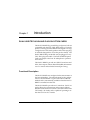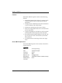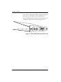
1
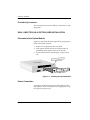
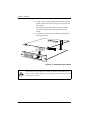
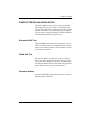
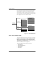
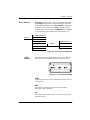
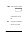
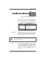
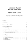
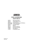
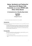
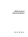
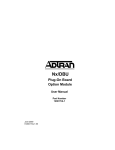
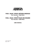
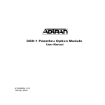
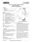
Dual U-BR1TE Plug-In Option Card
(Part Number 1200107L1#HS)
and Dual U-BR1TE Plug-On Option Card
(Part Number 1200108L1)
USER MANUAL
61200107L1#HS-1B
June 2000
901 Explorer Boulevard
P.O. Box 140000
Huntsville, AL 35814-4000
(256) 963-8000
© 2000 ADTRAN, Inc.
All Rights Reserved.
Printed in U.S.A.
Notes provide additional useful information.
Cautions signify information that could prevent service interruption.
Warnings provide information that could prevent damage to the
equipment or endangerment to human life.
iii
FCC regulations require that the following information be provided in this manual:
1. This equipment complies with Part 68 of the FCC rules. The required label is
affixed to the bottom of the chassis.
2.
3.
4.
5.
6.
7.
If this equipment causes harm to the telephone network, the telephone company may temporarily discontinue service. If possible, advance notification is
given; otherwise, notification is given as soon as possible. The telephone
company will advise the customer of the right to file a complaint with the
FCC.
The telephone company may make changes in its facilities, equipment, operations, or procedures that could affect the proper operation of this equipment;
advance notification and the opportunity to maintain uninterrupted service is
given.
If experiencing difficulty with this equipment, please contact ADTRAN for
repair and warranty information. The telephone company may require this
equipment to be disconnected from the network until the problem is corrected or it is certain the equipment is not malfunctioning.
This unit contains no user-serviceable parts.
An FCC-compliant telephone cord with a modular plug is provided with this
equipment. This equipment is designed to be connected to the telephone network or premises wiring using an FCC-compatible modular jack, which is
Part 68 compliant.
The following information may be required when applying to the local telephone company for leased line facilities.
Service Type
ISDN
iv
REN/SOC
FIC
USOC
6.0N
021S5
RJ-49C
FEDERAL COMMUNICATIONS COMMISSION RADIO FREQUENCY
INTERFERENCE STATEMENT
This equipment has been tested and found to comply with the limits for a Class
A digital device, pursuant to Part 15 of the FCC Rules. These limits are designed
to provide reasonable protection against harmful interference when the equipment is operated in a commercial environment. This equipment generates, uses,
and can radiate radio frequency energy and, if not installed and used in accordance with the instruction manual, may cause harmful interference to radio frequencies. Operation of this equipment in a residential area is likely to cause
harmful interference in which case the user will be required to correct the interference at his own expense.
Shielded cables must be used with this unit to ensure compliance with Class A
FCC limits.
Change or modifications to this unit not expressly approved by
the party responsible for compliance could void the user’s authority to operate the equipment.
CANADIAN EMISSIONS REQUIREMENTS
This digital apparatus does not exceed the Class A limits for radio noise emissions from digital apparatus as set out in the interference-causing equipment
standard entitled “Digital Apparatus," ICES-003 of the Department of Communications.
Cet appareil nuerique respecte les limites de bruits radioelectriques applicables
aux appareils numeriques de Class A prescrites dans la norme sur le materiel
brouilleur: "Appareils Numeriques," NMB-003 edictee par le ministre des Communications.
v
CANADIAN EQUIPMENT LIMITATIONS
Notice: The Canadian Industry and Science Canada label identifies certified
equipment. This certification means that the equipment meets certain telecommunications network protective, operational, and safety requirements. The
Department does not guarantee the equipment will operate to the user’s satisfaction.
Before installing this equipment, users should ensure that it is permissible to be
connected to the facilities of the local telecommunications company. The equipment must also be installed using an acceptable methods of connection. In some
cases, the company’s inside wiring associated with a single line individual service
may be extended by means of a certified connector assembly (telephone extension
cord). The customer should be aware that compliance with the above limitations
may not prevent degradation of service in some situations.
Repairs to certified equipment should be made by an authorized Canadian maintenance facility designated by the supplier. Any repairs or alterations made by
the user to this equipment, or equipment malfunctions, may give the telecommunications company cause to request the user to disconnect the equipment.
Users should ensure for their own protection that the electrical ground connections of the power utility, telephone lines and internal metallic water pipe system,
if present, are connected together. This precaution may be particularly important
in rural areas.
Users should not attempt to make such connections themselves,
but should contract the appropriate electric inspection authority,
or an electrician, as appropriate.
The Load Number (LN) assigned to each terminal device denotes the percentage
of the total load to be connected to a telephone loop which is used by the device,
to prevent overloading. The termination on a loop may consist of any combination of devices subject only to the requirement that the total of the Load Numbers
of all devices does not exceed 100.
vi
IMPORTANT SAFETY INFORMATION
SAVE THESE INSTRUCTIONS
When using your telephone equipment, please follow these basic safety
precautions to reduce the risk of fire, electrical shock, or personal injury:
1. Do not use this product near water, such as near a bathtub, wash bowl,
kitchen sink, laundry tub, in a wet basement, or near a swimming pool.
2.
3.
4.
Avoid using a telephone (other than a cordless-type) during an electrical
storm. There is a remote risk of shock from lightning.
Do not use the telephone to report a gas leak in the vicinity of the leak.
Use only the power cord, power supply, and/or batteries indicated in the
manual. Do not dispose of batteries in a fire. They may explode. Check
with local codes for special disposal instructions.
WARRANTY AND CUSTOMER SERVICE
ADTRAN will replace or repair this product within five years from the date of
shipment if it does not meet its published specifications or fails while in service.
For detailed warranty, repair, and return information refer to the ADTRAN
Equipment Warranty and Repair and Return Policy Procedure.
Return Material Authorization (RMA) is required prior to returning equipment
to ADTRAN.
For service, RMA requests, or further information, contact one of the numbers
listed on the back page of this manual.
vii
LIMITED PRODUCT WARRANTY
ADTRAN warrants that for five (5) years from the date of shipment to Customer,
all products manufactured by ADTRAN will be free from defects in materials and
workmanship. ADTRAN also warrants that products will conform to the applicable specifications and drawings for such products, as contained in the Product
Manual or in ADTRAN's internal specifications and drawings for such products
(which may or may not be reflected in the Product Manual). This warranty only
applies if Customer gives ADTRAN written notice of defects during the warranty
period. Upon such notice, ADTRAN will, at its option, either repair or replace the
defective item. If ADTRAN is unable, in a reasonable time, to repair or replace
any equipment to a condition as warranted, Customer is entitled to a full refund
of the purchase price upon return of the equipment to ADTRAN. This warranty
applies only to the original purchaser and is not transferable without ADTRAN's
express written permission. This warranty becomes null and void if Customer
modifies or alters the equipment in any way, other than as specifically authorized
by ADTRAN.
EXCEPT FOR THE LIMITEDWARRANTY DESCRIBED ABOVE, THE FOREGOING CONSTITUTES THE SOLE AND EXCLUSIVE REMEDY OF THE CUSTOMER AND THE EXCLUSIVE LIABILITY OF ADTRAN AND IS IN LIEU OF
ANY AND ALL OTHER WARRANTIES (EXPRESSED OR IMPLIED). ADTRAN
SPECIFICALLY DISCLAIMS ALL OTHER WARRANTIES, INCLUDING (WITHOUT LIMITATION), ALL WARRANTIES OF MERCHANTABILITY AND FITNESS FOR A PARTICULAR PURPOSE. SOME STATES DO NOT ALLOW THE
EXCLUSION OF IMPLIED WARRANTIES, SO THIS EXCLUSION MAY NOT
APPLY TO CUSTOMER.
In no event will ADTRAN or its suppliers be liable to Customer for any incidental, special, punitive, exemplary or consequential damages experienced by either
Customer or a third party (including, but not limited to, loss of data or information, loss of profits, or loss of use). ADTRAN is not liable for damages for any
cause whatsoever (whether based in contract, tort, or otherwise) in excess of the
amount paid for the item. Some states do not allow the limitation or exclusion of
liability for incidental or consequential damages, so the above limitation or exclusion may not apply to Customer.
viii
Table of Contents
List of Figures .............................................................................................................xi
List of Tables ........................................................................................................... xiii
Chapter 1. Introduction .......................................................................................... 1-1
Dual U-BR1TE Plug-in and Plug-on Option Cards ............................................. 1-1
Functional Description ...................................................................................... 1-1
Features ....................................................................................................... 1-2
Dual U-BR1TE Option Card ..................................................................... 1-2
Physical Description .......................................................................................... 1-3
Chapter 2. Installation ............................................................................................ 2-1
Unpack, Inspect, Power Up .................................................................................... 2-1
Receipt Inspection .............................................................................................. 2-1
ADTRAN Shipments Include........................................................................... 2-1
Provided by Customer ...................................................................................... 2-2
Dual U-BR1TE Plug-In Option Card Installation ................................................ 2-2
Placement of the Option Module ..................................................................... 2-2
Power Connection .............................................................................................. 2-2
Wiring .................................................................................................................. 2-3
Attaching the Plug-on Board to the Option Card ......................................... 2-3
Power Up Testing and Initialization ..................................................................... 2-5
Successful Self Test............................................................................................. 2-5
Failed Self Test .................................................................................................... 2-5
Operation Alarms............................................................................................... 2-5
Chapter 3. Operation............................................................................................... 3-1
Overview ................................................................................................................... 3-1
Menu Structure ................................................................................................... 3-1
Menu Operation ................................................................................................. 3-1
Dual U-BR1TE Menu Items ..................................................................................... 3-2
SYNC .................................................................................................... 3-4
CRC ....................................................................................................... 3-4
ACT ....................................................................................................... 3-4
TSU Features used with Dual U-BR1TE Options ................................................ 3-9
61200107L1#HS-1
Dual U-BR1TE Plug-in Option Card User Manual
ix
Table of Contents
Appendix A. Dual U-BR1TE Option Card Menu Tree .................................. A-1
Appendix B. Dual U-BR1TE Failure Messages................................................ B-1
x
Dual U-BR1TE Plug-in Option Card User Manual
61200107L1#HS-1
List of Figures
Figure 1-1. Dual U-BR1TE Plug-in Option Card .................................................. 1-3
Figure 1-2. Dual U-BR1TE Plug-on Option Card ................................................. 1-4
Figure 2-1. Installing the Option Module ............................................................. 2-2
Figure 2-2. Installing Plug-on Board...................................................................... 2-4
Figure 3-1. TSU 100 Main Menu............................................................................. 3-2
Figure 3-2. PORT STATUS Submenus...................................................................... 3-3
Figure 3-3. LOOP STATUS Display .......................................................................... 3-3
Figure 3-4. T1 STATUS Display ............................................................................... 3-4
Figure 3-5. PORT CONFIGURATION Submenus ....................................................... 3-5
Figure 3-6. Network Locations ............................................................................... 3-6
Figure 3-7. PORT UTILITY Submenus ...................................................................... 3-7
Figure 3-8. PORT TEST Submenus .......................................................................... 3-7
Figure A-1. Dual U-BR1TE Option Cards Menu Tree ........................................ A-1
61200107L1#HS-1
Dual U-BR1TE Plug-in Option Card User Manual
xi
List of Figures
xii
Dual U-BR1TE Plug-in Option Card User Manual
61200107L1#HS-1
List of Tables
Table 2-1. 2-Wire Voice Pinout Connection.......................................................... 2-3
Table 3-1. PORT CONFIGURATION Parameters........................................................ 3-5
Table 3-2. PORT TEST Parameters........................................................................... 3-8
61200107L1#HS-1
Dual U-BR1TE Plug-in Option Card User Manual
xiii
List of Tables
xiv
Dual U-BR1TE Plug-in Option Card User Manual
61200107L1#HS-1
Chapter 1
Introduction
DUAL U-BR1TE PLUG-IN AND PLUG-ON OPTION CARDS
The Dual U-BR1TE Plug-in and Plug-on Option Cards are
compatible with the TSU/TDU/HSU family of T1 multiplexers. The Plug-in Dual U-BR1TE is designed to occupy
a single slot in a TSU family product and will accept plugon modules designed for use in this product family. The
Dual U-BR1TE Plug-on Module may be plugged on any
TSU/TDU plug-in module. The Dual U-BR1TE Option
Cards are subject to the host T1 multiplexer's operation
and control.
The Dual U-BR1TEs provide two ISDN U-interfaces and
allow the transport of Basic Rate ISDN (BRI) information
over T1 carriers and unloaded twisted pair wiring.
Functional Description
The Dual U-BR1TEs are configured in the same manner as
the host multiplexer. The internal menu for the configuration of each U-BR1TE is a part of the Dual U-BR1TE
Module and is automatically available when the Dual UBR1TE is installed into the TSU.
The Dual U-BR1TEs provide two U-interfaces. Each U-interface allows the transmission and reception of Basic
Rate 2B+D information over three consecutive DS0s of the
TSU family's T1 facility and is capable of operating in either the LUNT or LULT mode.
61200107L1#HS-1
Dual U-BR1TE Plug-in Option Card User Manual
1-1
Chapter 1. Introduction
Features
Both Dual U-BR1TE Option Cards have the following
features:
•
Internal test pattern which allows for testing of individual B channels without requiring external test
equipment
•
Transportation of ISDN Basic Rate 2B+D information
over T1 facilities in the 3-DS0 format
•
Performance monitoring of the layer 1 facility
•
Firmware configurable to line unit LT or line unit NT
mode of operation
•
Loopback capability for full 2B+D as well as individual B channels in both loop and carrier directions
•
B1 and B2 looopback addressability for the NT1 and
up to six devices in the "downstream" (toward the
NT1) direction
•
Local performance monitoring without test equipment
Dual U-BR1TE Option Card
The Dual U-BR1TE Option Cards conform to the following specifications:
U-Interface
Line
1-2
2-wire (tip and ring)
Rate
160 kbps full duplex
Frequency
40 kHz
Line Code
2B1Q
Max Line Loss
42 dB @ 40 kHz
Max Distance
18000 ft with 1300 ohm resistance design
ISDN Interface
Connector
RJ-45
Dual U-BR1TE Plug-in Option Card User Manual
61200107L1#HS-1
Chapter 1. Introduction
Compatibility
ISDN 2B1Q Interface
ANSI T1.601-1992
Performance
TR-NWT-000397 and TR-TSY-000829
ISDN BR over T1
TR-NWT-000397
Approvals
FCC Part 15, FCC Part 68, UL
Diagnostics and Tests
Loopback
B1, B2 loopbacks and 2B+D loopbacks
initiated through EOC as specified by TRNWT-000397 and ANSI T1.601-1992
Selftest
RAM test
Slot selection test
EPROM checksum test
Physical Description
The Dual U-BR1TE Plug-in Option Card (see Figure 1-1)
is designed to occupy a single slot in a TSU family product.
DUAL U-BR1TE
PORT X.1
PORT X.3/X.4
PORT X.2
HOT
REPLACABLE
Figure 1-1. Dual U-BR1TE Plug-in Option Card
The Dual U-BR1TE Plug-in Option Card rear panel includes a plastic plug over a cutout for additional connectors. This allows a plug-on board to be added to the Dual
U-BR1TE Card. The PORT X.Y indication is linked to the
port numbering philosophy of the TSU 100 product family. The X represents the slot number, and the .Y indicates
the port number. For the TSU 100 application, there is
only one option slot. Therefore the ports are designated
1.1 and 1.2. If added, the plug-on board port designations
61200107L1#HS-1
Dual U-BR1TE Plug-in Option Card User Manual
1-3
Chapter 1. Introduction
are 1.3 and 1.4. These port numbers appear in the front
panel liquid crystal display (LCD) menu displays.
The Dual U-BR1TE Plug-on Option Card (see Figure 1-2)
is designed to plug on any TSU/DSU plug-in card.
DUAL U-BR1TE
PORT X.1
PORT X.3/X.4
PORT X.2
DUAL U-BR1TE
HOT
REPLACEABLE
Figure 1-2. Dual U-BR1TE Plug-on Option Card
1-4
Dual U-BR1TE Plug-in Option Card User Manual
61200107L1#HS-1
Installation
Chapter 2
UNPACK, INSPECT, POWER UP
Receipt Inspection
Carefully inspect the option module for any shipping
damage. If damage is suspected, file a claim immediately
with the carrier and contact ADTRAN Customer and
Product Service. If possible, keep the original shipping
container for use in shipping the option module for repair
or for verification of damage during shipment.
ADTRAN Shipments Include
The following items are included in ADTRAN shipments
of the Dual U-BR1TE:
Dual U-BR1TE Plug-in Option Card:
•
Dual U-BR1TE Plug-in Option Card
•
User Manual (to be inserted into main TSU 100/120/
600 User Manual)
Dual U-BR1TE Plug-on Option Card:
61200107L1#HS-1
•
Dual U-BR1TE Plug-on Option Card
•
User Manual (to be inserted into main TSU 100/120/
600 User Manual)
•
Four each #4 screws
Dual U-BR1TE Plug-in Option Card User Manual
2-1
Chapter 2. Installation
Provided by Customer
The customer must provide cables for connection to othe
equipment.
DUAL U-BR1TE PLUG-IN OPTION CARD INSTALLATION
Placement of the Option Module
Figure 2-1 represents the action required for proper placement of the option module.
1.
Remove cover plate from the rear panel.
2.
Slide option module into the rear panel until it is
positioned firmly against the front of the unit.
3.
Fasten thumb-screws at both edges of option module.
Cover Plate
TSU 100/120/600
Option Module
Figure 2-1. Installing the Option Module
Power Connection
Each option module derives power from the base TSU/
120/600 unit. Power to the base unit is supplied by a captive eight foot power cord.
2-2
Dual U-BR1TE Plug-in Option Card User Manual
61200107L1#HS-1
Chapter 2. Installation
Wiring
The option module offers two connectors for the U-interfaces. The connectors are universal and accept either an
RJ-45 (8-pin) or an RJ-11 (6-pin modular plug). The pinout
is given in Table 2-1.
The required wiring connections are:
Connector Type (USOC) = RJ-45
Part number = AMP # 555164-1
Table 2-1. 2-Wire Voice Pinout Connection
Pin
Name
Description
5
TIP
Tip lead of 2-wire
interface
4
RING
Ring lead of 2-wire
interface
1, 2, 3, 6, 7, 8
UNUSED
-
Pins used to mate with the Dual U-BR1TE connector are
as follows:
RJ-11
Tip
pin 4
Ring
pin 3
RJ-45
Tip
pin 5
Ring
pin 4
Attaching the Plug-on Board to the Option Card
Figure 2-2 represents the action required for proper placement of a plug-on board on the option card.
1.
61200107L1#HS-1
Hold the plug-on board above the option card.
Dual U-BR1TE Plug-in Option Card User Manual
2-3
Chapter 2. Installation
2.
Using a downward and right-to-left motion, slip the
DB-15 connector into the opening in the option card
back panel.
3.
Moving the plug-on board downward, secure the
connection of the header pins at the front of the
board.
4.
Install the four 4-40 screws at the top and bottom of
the plug-on board.
DXC
Nx 56/64
Port X.1
V.35
Nx 54/64
V.35
Figure 2-2. Installing Plug-on Board
The connection of the header pins between the option card and the plug-on
board must be visually verified. Severe damage of the device can result from
an improper connection.
2-4
Dual U-BR1TE Plug-in Option Card User Manual
61200107L1#HS-1
Chapter 2. Installation
POWER UP TESTING AND INITIALIZATION
The Dual U-BR1TE Option Card executes a partial self
test during the power up sequence, as described in the
TSU 100/120/600 manual. A full self test can be activated
from the Test menu. No initialization input is required.
Any previously configured setting for the Dual U-BR1TE
is restored automatically upon power up.
Successful Self Test
The green OK LED, located on the front panel, turns on
when a successful self test is completed and the configuration is successfully restored. See the chapter Operation
in the main user manual.
Failed Self Test
If the Dual U-BR1TE card fails one or more of the self
tests, a message is displayed in the LCD during power up.
See the TSU 100/120/600 user manual. Specific failures
of the Dual U-BR1TE Card are identified in the appendix
Dual U-BR1TE Failure Messages in this manual.
Operation Alarms
The red ALARM LED on the front panel turns on when an
alarm condition is detected.
61200107L1#HS-1
Dual U-BR1TE Plug-in Option Card User Manual
2-5
Chapter 2. Installation
2-6
Dual U-BR1TE Plug-in Option Card User Manual
61200107L1#HS-1
Chapter 3
Operation
OVERVIEW
The Dual U-BR1TE card is controlled as part of the TSU
100/120/600 using the same methods as described in the
TSU 100/120/600 User Manual. See the TSU 100/120/600
User Manual for descriptions of front panel indicators and
buttons.
Menu Structure
When an option card is installed in the TSU 100/120/600,
the unit adds it to the list of selectable options under the
Port menu items. These menu items are shaded in the
limited overview of the TSU 100 menu shown in Figure 31 on page 3-2. (The appendix of the TSU 100 User Manual
shows a complete menu diagram.)
Menu Operation
An option module must be selected from the listing in one
of the Port menu options before any option module
menus are applicable. With the cursor on one of the Port
menu items, press Enter to display a list of the currently
installed option modules. To activate menus for the Dual
U-BR1TE card, scroll through the list to display X.Y UBR1TE and press Enter. (The X represents the slot number,
and the Y identifies the port number.)
61200107L1#HS-1
Dual U-BR1TE Plug-in Option Card User Manual
3-1
Chapter 3. Operation
Once the option module is selected, the Dual U-BR1TE
menus appear as a subset of, and operate the same as,
menus for the TSU 100/120/600. Use the up and down arrows to place the cursor on the desired item, and press Enter to display the first two submenu choices.
1)NI PERF REPORTS
1)STATUS
2)CONFIG
TSU 100
MAIN MENU
2)NI ERRORS
1)NETWORK (NI)
3)ACTIVE ALARMS
2)UNIT
4)VIEW HISTORY
3)MAP XCHNG
5)PORT STATUS
4)MAP IN USE A (B)
6)REMOTE PORT
5)DS0 MAP A
6)CLEAR PORT ALM
6)DS0 MAP B
7)PORT CONFIG
3)UTIL
1)TIME/DATE
2)FACTORY RESTORE
3)NEW PASSCODE
4)TEST
1)NETWORK TESTS
4)UNIT ID
2)RUN SELF TEST
5)SOFTWARE REV
3)PORT TESTS
6)PORT UTIL
4)CANCEL TEST
Figure 3-1. TSU 100 Main Menu
DUAL U-BR1TE MENU ITEMS
The Dual U-BR1TE menus are accessed from, and operate
the same as, menus for the TSU 100/120/600. The Dual UBR1TE items are submenu choices of those four main
menus, as shown in Figure 3-1. For information on FACTORY RESTORE and RUN SELF TEST, see TSU Features used
with Dual U-BR1TE Options on page 3-9.
The Dual U-BR1TE menu items are as follows:
3-2
•
PORT STATUS
•
PORT CONFIGURATION
•
PORT UTILITY
•
PORT TEST
Dual U-BR1TE Plug-in Option Card User Manual
61200107L1#HS-1
Chapter 3. Operation
PORT STATUS
PORT STATUS, a submenu of TSU 100/120/600 main menu
item STATUS, displays active status information about the
Dual U-BR1TE interface. When PORT STATUS is displayed,
place the cursor on it and press Enter to display the first
available port. Scroll to select 1.1 U-BR1TE and press Enter
to activate either of the submenus shown in Figure 3-2.
1)NI PERF REPORTS
STATUS
2)NI ERRORS
3)ACTIVE ALARMS
4)VIEW HISTORY
5)PORT STATUS
1)LOOP STATUS
1.1 UBR1TE
6)REMOTE PORT
2)T1 STATUS
3)LOOP MONITOR
7)CLEAR PORT ALM
Figure 3-2. PORT STATUS Submenus
LOOP
STATUS
There are three information fields: SYNC, CRC, and ACT.
See Figure 3-3. An asterisk indicates an item is active.
Figure 3-3. LOOP STATUS Display
SYNC
An asterisk is present if the U-interface has achieved synchronization.
CRC
An asterisk is present when a CRC error has been
detected on the U-interface.
ACT
An asterisk is present if an NT1 is communicating with
the ISDN switch.
61200107L1#HS-1
Dual U-BR1TE Plug-in Option Card User Manual
3-3
Chapter 3. Operation
T1 STATUS
There are three information fields: SYNC, CRC, and ACT.
See Figure 3-4. An asterisk indicates an item is active.
Figure 3-4. T1 STATUS Display
SYNC
An asterisk is present if the U-interface has achieved synchronization to the T1 carrier.
CRC
An asterisk is present when a CRC error has been
detected on the T1 interface. (DS0s carrying U-BR1TE
data only.)
ACT
An asterisk is present if an NT1 is communicating with
the ISDN switch.
LOOP
MONITOR
PORT CONFIG
3-4
"ES=XXX"
Reports the maximum number of errored seconds on the
U-interface. Errored seconds are considered to be seconds in which the U-interface was not synchronized or
seconds in which at least one CRC error was detected on
the U-interface. This count can be set to zero by pressing
shift-clear when the cursor is at this menu item.
PORT CONFIG, a submenu of TSU 100/120/600 main
menu item CONFIGURATION, is used to configure the Dual
U-BR1TE. The submenu items shown in Figure 3-5 on
page 3-5 are used to configure the parameters.
Dual U-BR1TE Plug-in Option Card User Manual
61200107L1#HS-1
Chapter 3. Operation
1)SERVICE
2)CONFIG
7)PORT CONFIG
1.2 UBR1TE
2)ZBS
3)MODE
4)WAKE-UP TONE
Figure 3-5. PORT CONFIGURATION Submenus
The unit displays the first of four submenu items. Table 31 identifies the available selections for PORT CONFIGURATION. Continue with standard operating procedures.
Table 3-1. PORT CONFIGURATION Parameters
MENU ITEM
PARAMETER CHOICES
SERVICE
2B+D*, 2B, B1+D, B2+D, B1, B2
ZBS
DISABLE*, ENABLE
MODE
LULT*, LUNT
WAKE-UP TONE
OFF*, ON
*Factory Default
SERVICE
SERVICE allows the user to select the ISDN channels to
be transmitted over the T1 facility. Each channel requires
one DS0 of the T1 in which to transmit and receive data.
All switched applications will require the D channel.
The user must provision the proper number of consecutive DS0s of the T1
facility for proper operation.
ZBS
61200107L1#HS-1
For proper operation, the ZBS (zero byte substitution) for
two U-BR1TE ports connected by a T1 facility must be the
same value. The ENABLE parameter for ZBS must be selected if the T1 is using AMI line coding. If the T1 facility
is using B8ZS line coding, the DISABLE parameter may
be chosen.
Dual U-BR1TE Plug-in Option Card User Manual
3-5
Chapter 3. Operation
MODE
The U-BR1TE port should be configured to operate in the
LULT mode if being operated in the Adjacent to Customer
or Tandem Office Source positions (see Figure 3-6 on page
3-6). The MODE should be set to LUNT if the port is operated in the Adjacent to Switch or Tandem Office Sink positions.
WAKE-UP
TONE
Periodic wake-up tones should be turned on when the
port is operated in the Tandem Office Sink configuration
or when it is adjacent to a device that requires wake-up
tones.
2-Wire
ISDN
Switch
2-Wire
2-Wire
Dual U-BR1TE
Port
Dual U-BR1TE
Port
L
U
N
T
L
U
L
T
T Carrier
TSU
TSU
Adjacent to
Switch
Adjacent to
Customer
Dual U-BR1TE
Port
L
U
N
T
Customer
NT1
Dual U-BR1TE
Port
Dual U-BR1TE
Port
L
U
L
T
T Carrier
TSU
TSU
Adjacent to
Switch
Tandem Office
(Source)/U-Repeater
Dual U-BR1TE
Port
L
U
N
T
2-Wire
Loop
2-Wire
L
U
N
T
TSU
L
U
L
T
TSU
TSU
Adjacent to
Switch
Tandem Office
(Source)/U-Repeater
L
U
L
T
2-Wire
Loop
2-Wire
RP
2-Wire
Loop
Customer
NT1
TSU
Tandem Office (Sink)
Dual U-BR1TE
Port
T Carrier
Dual U-BR1TE
Port
T Carrier
Adjacent to Customer
Customer
NT1
U-Repeater
Figure 3-6. Network Locations
3-6
Dual U-BR1TE Plug-in Option Card User Manual
61200107L1#HS-1
Chapter 3. Operation
PORT UTILITY
PORT UTILITY, a submenu of the TSU 100/120/600 main
menu item UTILITIES (UTIL), displays the current software
information for each port installed in the unit. This information is required when requesting assistance from
ADTRAN Technical Support or when updates are needed.
When PORT UTILITY is displayed, place the cursor on it
and press Enter to display the first available port. See Figure 3-7.
1)TIME/DATE
3)UTIL
2)FACTORY RESTORE
3)SET PASSCODE
4)UNIT ID
5)SOFTWARE REV
6)PORT UTILITY
1.1 UBR1TE
SW REVISION
Figure 3-7. PORT UTILITY Submenus
Display 1.1 UBR1TE (scroll to display if necessary), and
press Enter. The unit displays the option card name and
the software version installed. Press Cancel to exit or select another port.
PORT TEST
PORT TEST, a submenu of the TSU 100/120/600 main
menu item TEST, activates tests of the selected data ports.
Selecting the Dual U-BR1TE displays tests available for
this option card. See Figure 3-8.
1)NETWORK TESTS
4)TEST
1)B1 REMOTE LPBK
2)RUN SELF TEST
3)PORT TEST
4)CANCEL TEST
2)B2 REMOTE LPBK
1.1 UBR1TE
3)LOCAL LOOPBACK
4)B1 2047 PATT
5)B2 2047 PATT
6)INJECT ERROR
7)PATT RESULTS
Figure 3-8. PORT TEST Submenus
61200107L1#HS-1
Dual U-BR1TE Plug-in Option Card User Manual
3-7
Chapter 3. Operation
Table 3-2 identifes the available selections for PORT TEST.
Table 3-2. PORT TEST Parameters
3-8
MENU ITEM
PARAMETER CHOICES
B1 REMOTE LPBK
ADDRESS 1, 2, 3, 4, 5, 6, NT1, NO LOOPBACK
B2 REMOTE LPBK
ADDRESS 1, 2, 3, 4, 5, 6, NT1, NO LOOPBACK
LOCAL LOOPBACK
B1, B2, NO LOOPBACK
B1 2047 PATT
T1_TX, LP_TX, NONE
B2 2047 PATT
T1_TX, LP_TX, NONE
INJECT ERROR
Inserts error into transmitted pattern
PATT RESULTS
Activates/deactivates the display of the test pattern’s errored seconds.
B1 REMOTE
LPBK
Remote loopbacks of the B1 channel in the network-tocustomer direction are initiated by selecting items under
this menu. The loopback may be requested for this unit
and the five next U-BR1TES toward the NT1. A LOOPING message is displayed on the LCD once a test has
been initiated. The initiating U-BR1TE sends the loopback
command and begins transmitting the internally generated 2047 pattern. When the U-BR1TE begins receiving the
2047 pattern, it displays FAR END LOOPED on the LCD.
The initiating U-BR1TE transmits the 2047 pattern for the
duration of the test. The user can view the pattern results
by choosing menu item 7)PATT RESULTS, and can inject
errors into the transmitted pattern by choosing menu
item 6)INJECT ERROR. Select NO LOOPBACK under
the B1 REMOTE LPBK menu to exit the test.
B2 REMOTE
LPBK
The B2 REMOTE LPBK operates exactly like the B1 REMOTE LPBK TEST, but the B2 channel is looped back rather than the B1 channel.
LOCAL
LPBK
The local U-BR1TE may be commanded to loop back either the B1 or B2 channel. When a channel is put in LOCAL
LOOPBACK, it will loop back both the T1 and U-interface
data associated with the channel.
Dual U-BR1TE Plug-in Option Card User Manual
61200107L1#HS-1
Chapter 3. Operation
B1 2047
PATT
A U-BR1TE port may be commanded to transmit the internally generated 2047 pattern on the B1 channel in either the T1 (T1_TX) or the U-interface (LP_TX) direction.
The pattern may be looped back to the U-BR1TE port and
verified with the results viewed by choosing 7)PATT RESULTS, or the 2047 pattern may be verified using test
equipment at accessible points in the network. Errors may
be injected into the transmitted pattern by choosing 6)INJECT ERROR.
B2 2047
PATT
B2 2047 PATT operates exactly like B1 2047 PATT, with
the pattern transmitted in the B2 channel instead of the B1
channel.
INJECT
ERROR
Selecting this menu item while the U-BR1TE is transmitting the 2047 pattern (B1 REMOTE LPBK, B2 REMOTE
LPBK, B1 2047 PATT, B2 2047 PATT) inserts an error in
the transmitted pattern.
PATT
RESULTS
Selecting this menu item while the U-BR1TE is transmitting the 2047 pattern causes the U-BR1TE to display the
maximum number of errored seconds of the test pattern
on the bottom line of the LCD (ES=xs). The display continues until this menu item is selected a second time.
Pressing shift-clear while in this menu resets the errored
seconds to zero.
TSU FEATURES USED WITH DUAL U-BR1TE OPTIONS
In addition to the Dual U-BR1TE menu items, two additional menu items of the TSU 100/120/600 may be operated in conjunction with the Dual U-BR1TE option
module. These are FACTORY RESTORE and RUN SELF
TEST.
FACTORY
RESTORE
61200107L1#HS-1
FACTORY RESTORE, a submenu of the TSU 100/120/600
main menu item UTIL (UTILITIES), restores the factory in-
Dual U-BR1TE Plug-in Option Card User Manual
3-9
Chapter 3. Operation
stalled default setting for all Dual U-BR1TE option module parameters.
When FACTORY RESTORE is displayed, place the cursor on
it and press Enter. The unit is restored to preset factory defaults and returns to the main menu. The factory default
for port configuration parameters is shown in Table 3-1
on page 3-5.
RUN SELF TEST
RUN SELF TEST, a submenu of the TSU 100/120/600 main
menu item TEST, executes both the Dual U-BR1TE internal test and the TSU 100/120/600 internal test. The results
of the self test are displayed in the LCD. See the TSU 100/
120/600 User Manual for additional information on SELF
TEST.
When RUN SELF TEST is displayed, place the cursor on it
and press Enter to execute the test. The unit continuously
changes the display in the LCD window until all test results are shown.
3-10
Dual U-BR1TE Plug-in Option Card User Manual
61200107L1#HS-1
Appendix A
Dual U-BR1TE Option
Card Menu Tree
The menu tree for the Dual U-BR1TE Plug-in and Plug-on
Option Cards is provided in Figure A-1.
1)Port Status
1)LOOP STATUS
2)T1 STATUS
3)LOOP MONITOR
1)SERVICE
2)Port Config
2)ZBS:
3)MODE
4)WAKE-UP TONE:
3)Port Utility
1)SW Revision
1)B1 REMOTE LPBK
2)B2 REMOTE LPBK
4)Port Test
3)LOCAL LOOPBACK
4)B1 2047 PATT
5)B2 2047 PATT
6)INJECT ERROR
7)PATT RESULTS
Figure A-1. Dual U-BR1TE Option Cards Menu Tree
61200107L1#HS-1
Dual U-BR1TE Plug-in Option Card User Manual
A-1
Appendix A. Dual U-BR1TE Option Card Menu Tree
A-2
Dual U-BR1TE Plug-in Option Card User Manual
61200107L1#HS-1
Appendix B
Dual U-BR1TE Failure
Messages
FAILURE MESSAGE AT POWER UP
The following messages indicate a probable component
failure on the Dual U-BR1TE Card:
E01 - EPROM CS
EPROM checksum error
E02 - RAM DATA Data Bus Failure
E03 - RAM ADDR Address Bus Failure
E04 - RAM CELL
61200107L1#HS-1
Ram Cell Failure
Dual U-BR1TE Plug-in Option Card User Manual
B-1
Appendix B. Dual U-BR1TE Failure Messages
B-2
Dual U-BR1TE Plug-in Option Card User Manual
61200107L1#HS-1
Product Support Information
Pre-Sales Inquiries and Applications Support
Please contact your local distributor, ADTRAN Applications Engineering, or
ADTRAN Sales:
Applications Engineering
(800) 615-1176
Sales
(800) 827-0807
Post-Sale Support
Please contact your local distributor first. If your local distributor cannot help,
please contact ADTRAN Technical Support and have the unit serial number available.
Technical Support
(888) 4ADTRAN
Repair and Return
If ADTRAN Technical Support determines that a repair is needed, Technical Support will coordinate with the Customer and Product Service (CaPS) department to
issue an RMA number. For information regarding equipment currently in house
or possible fees associated with repair, contact CaPS directly at the following number:
CaPS Department
(256) 963-8722
Identify the RMA number clearly on the package (below address), and return to
the following address:
ADTRAN, Inc.
CaPS Department
6767 Old Madison Pike
Progress Center
Building #6, Suite 690
Huntsville, AL 35807
RMA # _____________
iv