1
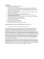
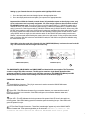
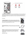
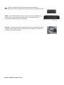
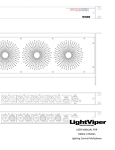
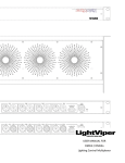
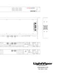
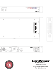
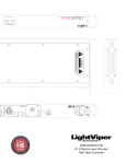
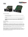
VIM-MY32
Functional Considerations
•
The LightViper VIM-MY32 cards contain no user serviceable parts. Please contact Fiberplex
directly with any service issues.
•
The LightViper VIM-MY32 cards are for use with Yamaha digital consoles containing YDGAI card
slots ONLY.
•
The VIM-MY32 cards are powered from the Yamaha console. ALWAYS POWER DOWN YOUR
CONSOLE BEFORE INSERTING OR REMOVING VIM-MY32 CARDS FROM YOUR
CONSOLE.
Standard Components
In its standard configuration, the Light Viper VIM-MY32 cards are made up of the following primary
components.
The VIM-MY32 Cards — The VIM-MY32 cards are available in (4) versions, (3) masters and (1) slave.
The VIM-MY32MST is a master card containing (2) ST fiber connectors. The VIM-MY32MOC is a master
card containing a single Neutrik OpticalCon connector. The VIM-MY32MT4 is a master card containing a
single TAC-4 (four fibers) connector. The VIM-MY32S is a slave card and contains no fiber connectors.
The Master / Slave Interconnect cable – each master / slave pair purchased comes with a high speed
Neutrik 12 pin MiniCon™ connector. This cable connects the master card to the slave card.
The Fiber Jumper Cable – For those purchasing VIM-MY32MT4 cards with a system of 48 or 64
channels, a duplex PVC fiber cable is supplied to connect the fiber “pass-throughs” on the VIM-MY32MT4
to the VIM-MY32MST card. In 48 or 64 channel configurations, (2) master modules are required. This
jumper connects one master card to the other.
1
Getting Started
To install your VIM-MY32 cards please follow these steps:
1. Power down your Yamaha console
2. Set clock master / slave switch on master card(s). This switch is found on the VIM-MY32M
(master) circuit board. If the VIM-MY32 clock on the VIM-MY32M is being used as the main
system clock, switch this to “Master”. If the Yamaha console internal clock is being used as the
master clock, set this switch to “Slave”
3. Insert cards into appropriate YGDAI card slots, aligning the sides of the card with the with the
support guides in the YGDAI slot
4. Connect master / slave cards with supplied Neutrik MiniCon cable
5. Connect (if applicable) supplied fiber pass-through cable (VFC-0001-DST) between VIMMY32MT4 and VIM-MY32MST cards.
6. Press the VIM-MY32 card firmly in place ensuring a complete connection between the multipin
back plane of the VIM-MY32 card and the console
7. Secure the VIM-MY32 card with supplied thumb screws
8. Power up your Yamaha console
9. Check to see that “slave” LED is solid green
10. Ensure that the “sync” LED is solid green
11. Input audio signals and check for audio in both directions
Advanced functions of the Light Viper VIM-MY32 cards (control, clocks, etc.)
1. Using Yamaha control protocol with the LightViper VIM-MY32 cards
On the VIM-MY32S (slave) card, there are DB9 and RJ45 connectors. These connectors are used to
input control from your Yamaha into the LightViper system to remotely control digital microphone
preamplifiers (i.e. Yamaha AD8HR, Aphex 1788A, etc.). The RJ45 connector is for use with the
LightViper DGL-422 cable only. This cable contains active electronics that translate the Yamaha control
protocol for the LightViper system. The DB9 connector may be used with a straight DB9 to DB9 cable,
utilizing the translation electronics on the VIM-MY32 card itself. The switch in between these connectors
should be set to correspond with the connector being used (left or “TTL” for the RJ45, right or “HA” for the
DB9 connector. In the case of the Yamaha LS9, this console has no external control connector. Control is
fed internally to the back plane of the VIM-MY32 card itself. If you are using VIM-MY32 cards with a
Yamaha LS9, the switch should be set to the middle “internal” position. Accessory LightViper products
such as DGL-422 (Yamaha control protocol), MD3 (RS-422, MIDI, RS232 control) and DMX4 (DMX
lighting control plus Yamaha control).
The Yamaha console will not display “VIM-MY32” on the console screen. The Yamaha console will
recognize the VIM-MY32 card as a generic 16-channel expansion card. The name shown in the text field
will be displayed as a generic name (i.e. “ADAT 16”). What is displayed may vary with the model and/or
software version being run on the Yamaha console. Some Yamaha mixers may not be compatible with
the LightViper VIM-MY32 cards. Software and firmware updates to the console may be required. Consult
with Yamaha customer service or your console manual for additional information.
2
Setting up your Yamaha Console for operation with LightViper MY32 cards.
1. Go to the input patch screen and assign inputs to the appropriate slots
2. Go to the output patch section and patch your outputs to the appropriate slots
Important Note: While the Yamaha console shows (16) patchable outputs on the display screen, only
(8) on each master card are actually assignable. You must assign outputs to the slot which contains
the VIM-MY32 master card. There are (8) returns on a 32x8 system utilizing (1) VIM-MY32 master and (1)
VIM-MY32 slave; (16) returns on a 48x16 system utilizing (2) VIM-MY32 masters and (1) VIM-MY32 slave;
and (16) returns on a 64x16 system with (2) VIM-MY32 masters and (2) VIM-MY32 slaves. When using VIMMY32S (slave) cards on a split, none of the control functions are operational from these split positions – only
the primary VIM-MY32S cards located at FOH have the capability of utilizing these control functions. When
using VIM-MY cards on a split, the clock selection switch on the VIM-MY32 master card(s) must be set to
“Master”, as these cards will be feeding the master clock to the split console. If using a system that contains
both a LightViper VIM-1832 mixer box and VIM-MY32 cards, the VIM-1832 must operate at 24bit/48k using
the external clock input.
Note: When using the cards with a Yamaha LS9, the VIM-MY32M (Master) card must be used in slot #1
only. The control must also be assigned to slot #1 only.
5
VIM-MY32MT4 (Master)
6
7
9
VIM-MY32S (Slave)
8
The VIM-MY32MT4, VIM-MY32MOC and VIM-MY32MST are identical with one exception. The T4 versions
contains a single TAC-4 fiber connector, The OC version contains a single Neutrik OpticalCon fiber
connector, and the ST version contains a pair of ST fiber connectors. The VIM-MY32T4 (Master) and VIMMY32S (Slave) card are shown here. Drawings of all versions can be found on page 14.
VIM-MY32M – Master Card
1
Neutrik MiniCon Connector – This (12) pin connector is used to connect the VIM-MY32M master
card to the VIM-MY32S slave card.
2 Slave LED – This LED shows the status of your connection between your master and slave cards. If
the LED is not lit, there is no connection. If the LED is solid green, the connection between master and
slave cards is active.
3
Sync LED – This LED indicates the clock sync status of the system.If the LED is not lit, the card is not
receiving power. If the LED is flashing green this means the system is searching for sync. If the LED is solid
green the system is in sync.
4 ST Fiber Pass Through Connectors – These fiber “pass-throughs” appear only on the VIM-MY32MT4
version of master card. These pass troughs allow you to access the additional (2) fibers in a TAC4 connectos and connect them with the additional VIM-MY32MST master card in systems
3
with 48 or 64 channels. On a 32channel system, these ST “pass-throughs” would not be
used as there is only (1) master required for a 32x8 system.
5
Fiber Connector – The main fiber connection illustrated above contains a TAC-4
connector. Other versions contain either a single Neutrik OpticalCon fiber-optic
connector, or (2) ST fiber-optic connectors.
VIM-MY32S – Slave Card
6
Neutrik MiniCon Connector – This (12) pin connector is used to connect the
VIM-MY32M master card to the VIM-MY32S slave card.
7
TTL CTL Connector – This connector is for use with the LightViper DGL-422 control cable, as well as
LightViper MD3 or DMX4 units.
8
CTL / SEL Switch – This switch determines which connector on the VIM-MY32S (Slave) card is active.
Swtich to the left for RJ45 “TTL CTL”, center for LS9 (“back plane”) control, and right for DB9 “HA” control.
9 HA/Remote Connector – This connector is for connecting a stright DB9 to DB9 cable from the DB9
control output connector on the Yamaha console to the DB9 on the VIM-MY32S card.
4
Clock Master / Slave Switch - This switch is found on the VIM-MY32M(master) circuit board. If the VIM-MY32 clock
on the VIM-MY32M is being used as the main system clock, switch this to “Master”. If the Yamaha console internal
clock is being used as the master clock, set this switch to “Slave”. When using VIM-MY cards on a split, the clock
selection switch on the VIM-MY32 master card(s)must be set to “Master”, as these cards will be feeding the master clock
to the split console.
Fiber Options
Tactical grade military fiber - (TAC-4) is used for live production applications (P/N
TFC-0000-04). Weighing 8.4 lbs.(12.6kg) for(300)feet, this cable contains (4) fibers and
therefore it is capable of carrying the signals of (2) VIM-1808/0808 systems on a single
cable. The TAC-4 connectors are hermaphroditic and can be connected to one another.
Multimode fiber can transport signals up to 2km (1.25 miles).
TAC-4
Neutrik OpticalCon® Fiber – this fiber cable contains (2) fibers and is also a tactical
grade fiber (P/N TFC-0000-02OC). This fiber cable is transporting (1) VIM-1808/0808
system.
Neutrik OpticalCon
Fiber Cable & Panel
Mount Connector
PVC fiber – PVC duplex fiber contains (2) fibers. Plenum rated fiber is also available.
The installer can terminate the fiber themselves, or Fiberplex can supply it preterminated. This fiber is also available with a strain relief and “pulling eye” which
reduces on site labor. A single length of PVC duplex fiber can transport (1) VIM1808/0808 system.
Plenum Install Fiber
ADDITIONAL OPTIONS
5
MD3 – A pair of LightViper MD3 units may be used to transport RS-422,
MIDI or RS-232 from FOH to stage via the RJ45 connector on the VIM-MY32S card.
MD3 – FRONT & BACK
DMX4 – A pair of DMX4 enables the user to send (4) universes of DMX lighting
control data, or (3) universes and Yamaha control. The Yamaha control is
connected via the DB9 connector on the DMX4.
DMX4i & DMX4o
DGL-422 – This interconnect cable contains active electronics and allows the user to
transport Yamaha control from the Yamaha console to the stage unit via the RJ45
connector on the VIM-MY32S card.
DGL-422
LightViper VIM-MY32 Card Specifications
6
[Buddy to insert spec’s here]
7
8
9
10