1
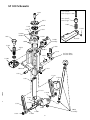
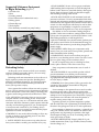
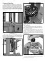
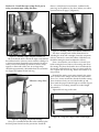
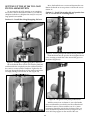
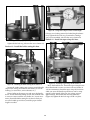
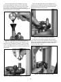
illon
recision
Products, Inc.
AT 500
Instruction Manual
Version 3.3
AT 500 Parts List
Table of Contents
Subject
Part #
13409
13435
13583
13593
13650
13700
13728
13738
13747
13757
13775
13781
13789
13794
13817
13824
13825
13830
13834
13841
13881
13886
13890
13891
13904
13909
13923
13966
13967
13996
13997
14008
14013
14033
14280
Description
Crank
1/4” Hex Wrench
Link Arm, Left
5/32” Hex Wrench
Spent Primer Cup
Link Arm Pin
1/8” Hex Wrench
Rod Washer, #10
Link Arm w/ Hook, Right
Seating Punch, Small
Main Shaft
Platform
Main Shaft Pin Set Screw
Shellplate Bolt
10-32 Kep Nut
Primer Cup, Large
Primer Cup, Small
Main Shaft Pivot Pin
Solid Link Arm Pin, Left
Nylock Nut
Hollow Link Arm Pin, Right
3/32” Hex Wrench
Spring Washer
Index Ball
Bellcrank Bolt
Toolhead
Brass Tip Set Screw
Platform Mount Bolt
Seating Punch, Large
10-32 x 3/16 Set Screw
Index Ball Spring
Toolhead Pin
Roller Bracket Screw
Primer Cup Spring
Roller Bracket Assembly
13719 Cartridge Spring Screw
13926 Cartridge Spring
16609 Conversion Kit
16610 Universal Shellplate
16611 Shellplate Cover
16612 Primer Punch Holder
16617 Plastic Funnel
16629 Powder Die
20094 Frame
20636 Handle, Knob & Nut Assembly
Not all items are shown in schematic illustration.
Page #
AT 500 Parts List
2
AT 500 Machine Schematic
3
Minimum Equipment to Begin Reloading 4
Reloading Safety
4
Parts List
4
Mounting the AT 500 to Your Bench
5
Configuring the AT 500
5
Changing Shellplate Position
5
Caliber Conversion Chart
6
Changing Primer Size
7
The Toolhead
7
Setting Up to Load Rifle Ammunition
8
Setting Up to Load Pistol Ammunition
11
The Reloading Process
13
AT 500 Upgrades and Accessories
15
Dillon Precision Products, Inc.
8009 E. Dillon’s Way
Scottsdale, AZ 85260
(480) 948-8009
(480) 998-2786 FAX
For Technical Assistance
or to place an order call: (800) 223-4570
For an issue of the Blue Press: call:
(800) 762-3844
For additional product information,
see our web site at:
www.dillonprecision.com
2
#16618 Spot Manuals
AT500 Folder
AT500 Manual. V 3.3 9/01 WJC
AT 500 Schematic
13757 (Small)
13967 (Large)
13794
13825 (Small)
13824 (Large)
16611
13891
13997
13996
13966
Locator
Buttons
16617
14033
16610
13781
16612
14280
assembly
14008
13996
13904
16629
14013
13738
13881
See box above
for more detail.
13909
20094
13817
13834
13747
13650
13923
13775
13841
13890
13789
13583
13830
13409
20636
Assembly
13700
13841
13890
3
• LEAD WARNING: Be sure to have proper ventilation
while handling lead components or when shooting lead
bullets. Lead is known to cause birth defects, other reproductive harm and cancer. Wash your hands thoroughly
after handling anything made of lead.
Suggested Minimum Equipment
to Begin Reloading (Figure 1)
1) Powder scale
2) Dies
3) Loading manual
4) Case lubricant (for bottlenecked cases)
5) Safety glasses
6) Primer flip tray*
7) Dial calipers*
(*Not absolutely essential, but pretty handy.)
• LOADS AND LENGTHS: Avoid maximum loads and
pressures at all times. Use only recommended loads from
manuals and information supplied by reliable component
manufacturers and suppliers. Since Dillon Precision has no
control over the components which may be used on their
equipment, no responsibility is implied or assumed for
results obtained through the use of any such components.
Seat bullets as close to maximum cartridge length as
possible. Under some conditions, seating bullets excessively deep can raise pressures to unsafe levels. Refer to a reliable loading manual for overall length (OAL).
• QUALITY CHECKS: Every 50-100 rounds, perform periodic quality control checks on the ammunition being produced. Check the amount of powder being dropped and
primer supply.
• RELOADING AREA: Keep your components safely
stored. Clear your work area of loose powder, primers and
other flammables before loading.
• COMPONENTS: Never have more than one type of
powder in your reloading area at a time. The risk of a mixup is too great. Keep powder containers closed.
Be sure to inspect brass prior to reloading for flaws,
cracks, splits or defects. Throw these cases away.
Figure 1– Minimum equipment needed to begin reloading.
Keep components and ammunition out of reach of
children.
Reloading Safety
At this point you’re anxious to finish your assembly
and start cranking out rounds. But for your own safety,
stop now and read the following:
• BLACK POWDER: Do not use black powder or black
powder substitutes in any Dillon powder measure.
Loading black powder cartridges requires specialized loading equipment and techniques. Failure to do so can result
in severe injury or death.
Reloading small arms ammunition involves the use of
highly explosive primers and powder. Handling these
materials is inherently dangerous. You should recognize
this danger and take certain minimum precautions to
lessen your exposure to injury.
• PRIMERS: Never force primers. If they get stuck in the
operation of the machine, disassemble it and gently
remove the obstruction.
Never operate the machine without ear and eye protection on. Call our customer service department at (800) 2234570 for information on the wide variety of shooting/safety glasses and hearing protection that Dillon has to offer.
Never attempt to clear primers that are stuck in either
the primer pickup tube or the primer magazine tube.
Never, under any circumstances, insert any type of rod to
attempt to force stuck primers out of these tubes. Trying to
force primers out of the tube will cause the primers to
explode causing serious injury or even death.
• PAY ATTENTION: Load only when you can give your
complete attention to the loading process. Don’t watch
television or try to carry on a conversation and load at the
same time. Watch the automatic systems operate and make
sure they are functioning properly. If you are interrupted
or must leave and come back to your loading, always
inspect the cases at every station to insure that the proper
operations have been accomplished.
If primers get stuck in a primer magazine or pickup
tube flood the tube with a penetrating oil (WD-40), throw
the tube in the garbage and call us for a free replacement.
Never attempt to deprime live primers – eventually one
will go off. When it does it will detonate the others in the
spent primer cup. Depriming live primers is the single
most dangerous thing you can do in reloading and can
cause grave injury or death.
• SMOKING: Do not smoke while reloading or allow anyone else to smoke in your reloading area. Do not allow
open flames in reloading area.
• LOADED AMMUNITION: Properly label all of your
loaded ammunition (Date, Type of Bullet, Primer, Powder,
Powder Charge, etc.).
• SAFETY DEVICES: Do not remove any safety devices
from your machine or modify your machine in any way.
4
• BE PATIENT: Our loading equipment is conservatively
rated and you should have no trouble achieving the published rates with a smooth, steady hand. If something
doesn’t seem right, stop, look and listen. If the problem or
the solution isn’t obvious, call us. The reloading bench is
no place to get into a hurry.
MOUNTING THE AT 500
TO YOUR BENCH
Place your AT 500 on the edge of a sturdy bench or
table where you plan to mount it. Give yourself about 12
inches of work space on each side of the machine to allow
room for components.
We have done everything we know how to make your
machine as safe as possible. We cannot, however, guarantee your complete safety. To minimize your risk, use common sense when reloading and follow these basic rules.
Using the machine itself as a template, mark and drill
four 1/4” holes in your bench and bolt your AT 500
securely to it. (Figure 3)
• REMEMBER: If your machine does not perform to your
expectations, or if you are having technical difficulties,
give us a call. Technical Support (800) 223-4570
All electrical/electronic components in Dillon equipment are covered by a one-year warranty.
Your AT 500 comes complete with:
• AT 500 Machine
• Operating Handle Assembly including:
Handle Shaft
Handle Knob
Nylock Nut and Washer
• Accessory Bag including: (Figure 2)
Small Primer Cup and Pin
Note: The Large Primer Assembly comes installed in
the machine.
Plastic Funnel
Spent Primer Cup
Hex Wrenches: 1/8”, 1/4”, 5/32” and 3/32”
Powder Die with Lock Ring
• Conversion Kit including: (Figure 2)
Powder Funnels: A, B and K for Rifle – W, E, D
and F for Pistol calibers
Locator Pins: #1, #2 and #3
Figure 3 – Using the reloader as a template to mark your bench.
Avoid using wood or lag screws to mount your
reloader to the bench. These types of screws can loosen
over time.
CONFIGURING THE AT 500
Install the handle and spent primer cup. (Figure 4)
Double-check now to make sure all the parts needed
are present. (Figure 2)
Use hole in handle
for leverage while
tightening nut.
B
D
A
C
Spent
Primer
Cup
G
E
F
Figure 2– A) Spent Primer Cup B) Plastic Funnel C) Hex
Wrenches D) Powder Die with Lock Ring E) Powder
Funnels F) Small Primer Cup and Pin G) Locator Buttons
Figure 4 – Installation of the handle and spent primer cup.
5
Changing Shellplate Position
Your AT 500 is shipped with the “universal” shellplate
installed. The “universal” shellplate has four shellholder
slots: #1, #2, #3 and #5. This allows you to reload a wide
variety of calibers.
All AT 500 reloaders are shipped with the #1 slot visible. If the caliber you wish to load requires one of the
other slots on the shellplate (see the caliber conversion
chart on page 3 to be sure), you may change this by first
loosening the brass-tipped set screw (Figure 5) at the top
left side of the shaft, just below the shellplate platform,
with the supplied 1/8” hex wrench.
Figure 5 – Location of the shellplate bolt set screw.
Next, loosen the shellplate bolt with the 1/4” hex
wrench. Then reposition the shellplate cover to display the
slot you desire to use. The shellplate cover has two dimples (Figure 6) to help you align it with the shellplate.
Figure 6 – Locator “dimples” on the AT 500 shellplate cover.
Tighten the shellplate bolt with the hex wrench – then
back the shellplate bolt out about 1/4 turn so that you can
rotate the shellplate easily. There should be no looseness or
“slop” at this point. When you rotate the shellplate, you
should be able to feel and hear the shellplate “click” into
place. Re-tighten the brass-tipped set screw under the
shellplate platform to prevent the shellplate bolt from
rotating as the shellplate is indexed.
6
Caliber Conversion Chart
Caliber
Shellplate
Slot
Powder
Funnel
Locator
Button
Rifle Calibers
.222 Rem.
.22-250
.223 Rem.
.240 Wby. Mag.
.243 Win.
.250 Savage
.25-06
.257 Roberts
.257 Ackley Imp.
.270 Win.
.284 Win.
.30-06
.308
.358 Win.
.35 Whelen
6mm Rem.
6.5-06
6.5x55
7mm-08
7.65x53
7x57
7.7 Arisaka
7mm B.R.
7mm Exp./280 Rem.
7mm Int’l Rim
7.5x55 Swiss
8x57
3
1
3
1
1
1
1
1
1
1
1
1
1
1
1
1
1
1
1
1
1
1
1
1
1
1
1
A
A
A
K
K
K
K
K
K
K
K
B
B
B
B
K
K
K
K
B
K
B
K
K
K
B
B
3
1
3
1
1
1
1
1
1
1
1
1
1
1
1
1
1
1
1
1
1
1
1
1
1
1
1
Handgun Calibers
.22 Rem. Jet
.221 Rem. Fireball
.380 ACP
.38 Super
.38/.357 Mag./Max.
.357 SIG
.45 ACP
7 TCU
9mm
9x25
9x21
10mm/.40 S&W
2
3
3
5
2
5
1
3
5
5
5
5
A
A
F
F
D
F
E
K
F
F
F
W
2
A
3
3
2
2
1
3
3
2
3
2
Changing Primer Size
Your AT 500 has been shipped to you with the large
primer bar installed and correctly adjusted to feed large
primers. If the caliber you have selected requires small
primers, you must change to the small primer cup and
pin. Do this by loosening the set screw and removing the
large primer cup and pin from the primer bar. Install the
small primer cup and pin. (Figure 7) Do not tighten the
set screw yet.
Figure 9 – The primer cup, showing through the platform.
The Toolhead
Your new AT 500 is equipped with a removable toolhead. Additional toolheads are available from the factory
or your local Dillon dealer.
The advantage of this system is simple. Once you have
adjusted your dies just the way you want them, they can
stay that way. Plus, changing to another caliber becomes a
simple matter of pulling two pins and sliding the toolhead
out. (Figure 10)
Figure 7 – To change the primer cup and pin, loosen this set
screw. See arrow.
This set screw needs to be loose in order to align the
primer cup with the platform. Lower the platform onto the
primer cup (Figure 8), then tighten the set screw while the
cup is in the platform. (Figure 9)
Platform
Primer Cup
Figure 10 – Removing the toolhead.
Figure 8 – Lowering the platform onto the primer cup.
Before you begin loading, make sure that the toolhead
is secured by the toolhead pins.
7
3
2
4
1
Figure 13 – Placing the cartridge case in the shellplate.
Figure 11 – Toolhead/die station orientation.
Move the handle down to resize and deprime the case.
Return the handle to its rest position.
SETTING UP THE AT 500 TO LOAD
RIFLE AMMUNITION
Examine the case you just resized and deprimed. If a
case gage is available, insert the case into the gage to
(Figure 14) assure yourself that the case has been resized
properly. (The bottom of the case should be flush with the
bottom of the gage.)
We are using the .30-06 cartridge as an example in this
section. The AT 500 machine comes to you with the
shellplate (with the #1 slot ready for use) and large primer
bar installed.
Station #1 – Install the sizing/decapping die here.
Figure 12 – Installing the sizing/decapping die in Station #1.
Move the handle down (which will raise the platform)
and thread the sizing/decapping die completely into the
toolhead until the die comes in contact with the shellplate.
Return the handle to its rest position (up).
Figure 14 – Inserting a case in a case gage.
Rotate the sizing/decapping die in or out as needed to
reach the proper case-to-gage fit. After the die is adjusted,
tighten the die lock ring to hold it in place. Advance the
case to Station #2.
Wipe a small amount of case lube on the body and neck
of an empty .30-06 cartridge case, then place the case into
the #1 slot. (Figure 13)
Station #2 – Install the powder die and powder funnel here (We are using powder funnel “B” for the
.30-06 cartridge – See Figure 15)
8
Station #3 – Install the bullet seating die here.
Place a bullet on the empty case and move the handle
down. Thread the bullet seating die into the toolhead until
it comes in contact with the case/bullet. (Figure 17)
Figure 15 –Installing rifle powder funnel into the powder die.
Slide the funnel into the powder die and tighten the set
screw, assuring yourself that it has entered the groove in
the funnel. (Figure 16)
Figure 17 – Installing the bullet seating die in Station #3.
In 1/4 turn increments, thread the bullet seating die
clockwise while you move the handle up and down, until
the proper loaded length is reached. (Always use a loading
manual for loaded length information.) Tighten the die
lock ring and the lock ring on the seating stem. (Figure 18)
Figure 16 – The groove in the rifle powder funnel.
With the resized case in Station #2, move the handle
down and thread the powder die into the toolhead until
the funnel comes in contact with the case. Tighten the die
lock ring. Advance the case to Station #3.
Figure 18 – Tightening the lock ring on the seating stem.
Examine the cartridge you’ve just assembled, checking
the overall length. Advance the cartridge to Station #4.
9
three #1 (.30-06) brass locator buttons, included in the
parts bag, on the platform. (For other calibers, see caliber
conversion chart on page 3.) (Figure 21)
Station #4 – Install the taper crimp die (if you’re
using a separate taper crimp die) here.
Figure 21 – Installing a brass locator button at Station #2.
The above example used a Dillon three-die set for
reloading the .30-06 rifle cartridges. Some die companies
offer two die-sets for some rifle calibers. With these sets,
the bullet seating die must be adjusted as follows:
Figure 19 – Installing a taper crimp die in Station #4.
Move the handle down. Thread the taper crimp die into
the toolhead until it comes in contact with the cartridge. In
1/4 turn increments, thread the taper crimp die clockwise
while you move the handle up and down, until a crimp
appears on the mouth of the case. An average crimp
should be approximately .002 smaller than the case diameter. (Figure 20) Tighten the die lock ring.
Place a resized rifle case in Station #3. Install your
bullet seating die here. Remove the seating stem from
the seating die. Move the handle down and thread the
die into the toolhead until it comes in contact with the
case. Tighten the die lock ring. Return the handle to its
rest position.
Reinstall the seating stem approximately five turns.
Place a bullet on the empty case and move the handle
down. In 1/4 turn increments, thread the bullet seating
stem clockwise while you move the handle up and
down until the proper loaded length is reached. (Figure
22 – Always use a loading manual for loaded length
information.)
Measure crimp here.
Tighten the lock ring on the stem.
Figure 22 – Using a dial caliper to check overall length.
Figure 20 – A properly crimped rifle cartridge.
Once you’ve installed all the dies in the toolhead, place
the black plastic funnel onto the powder die. Install the
10
Move the handle down to resize and deprime the case.
Return the handle to its rest position. Advance the case to
Station #2.
SETTING UP THE AT 500 TO LOAD
PISTOL AMMUNITION
We are using the .45 ACP cartridge as an example in
this section. The AT 500 machine comes to you with the
shellplate (with the #1 shellplate slot ready for use) and
large primer bar installed.
Station #2 – Install the powder die and powder funnel “E” for the .45 ACP cartridge here.
Station #1 – Install the sizing/decapping die here.
Figure 25 – Insert a pistol powder funnel into the powder die.
Slide the funnel into the powder die and tighten the set
screw, assuring yourself that it has entered the groove in
the funnel. (Figure 26)
Figure 23 – Installing a sizing/decapping die in Station #1.
Move the handle down (which will raise the platform)
and thread the die completely into the toolhead until the
die comes in contact with the shellplate. Tighten the die
lock ring. Return the handle to its rest position and insert
an empty cartridge case into the #1 slot. (Figure 24)
Figure 26 – The groove in the pistol powder funnel.
With the resized case in Station #2, move the handle
down and thread the powder die into the toolhead until
the funnel comes in contact with the case. In 1/4 turn
increments, thread the powder die clockwise while you
move the handle up and down until you begin to see a
minor bell shape appear on the mouth of the case.
Figure 24 – Inserting an empty cartridge case in Station #1.
11
Figure 29 – Using a dial caliper to check overall length.
(Always use a loading manual for loaded length information.) Tighten the die lock ring. Examine the cartridge
you’ve just assembled. Advance the case to Station #4.
Station #4 – Install the taper crimp die here.
Figure 27 – A properly belled pistol case.
Tighten the die lock ring. Advance the case to Station #3.
Station #3 – Install the bullet seating die here.
Figure 30 – Installing a taper crimp die in Station #4.
Figure 28 – Installing the bullet seating die in Station #3.
Move the handle down. Thread the taper crimp die into
the toolhead until it comes in contact with case/bullet. In
1/4 turn increments, thread the taper crimp die clockwise
while you move the handle up and down, until a crimp
appears on the mouth of the case. An average crimp is
approximately .002 smaller than the body diameter.
(Figure 30) Tighten the die lock ring to hold it in place.
Inspect the inside seating stem. Assure yourself that the
shape of the seating stem matches the bullets you will be
loading (i.e. round-nose, semi-wadcutter, etc.).
Place a bullet on the empty case and move the handle
down. Thread the bullet seating die into the toolhead until
it comes in contact with the case/bullet. In 1/4 turn increments, thread the bullet seating die clockwise while you
move the handle up and down, until the proper loaded
length is reached.
12
THE RELOADING PROCESS
The following is a list of items you will need before
you begin. (Figure 33)
1) Empty brass casings
2) Primers
Measure crimp here.
3) Powder scale
4) Loading manual
5) Powder (see manual)
6) Bullets (see manual)
7) Dial calipers
8) Safety glasses
Figure 31 – A properly crimped pistol cartridge.
Once you’ve installed all the dies in the toolhead, place
the black plastic funnel onto the powder die. Install the
three #1 (for .45 ACP) brass locator buttons, included in
the parts bag, on the platform. (Figure 32)
Figure 33 – What you will need to start loading.
To begin, place an empty case in Station #1 and move
the handle down. While the handle is in the down position, place a new primer in the primer cup. (Figure 34)
Return the handle to its rest position and insert the new
primer into the case by pushing the handle forward.
Figure 32 – Installing a brass locator button in Station #2.
Figure 34 – Placing a primer in the primer cup at Station #1.
13
Place your left thumb on the shellplate cover and
advance the shellplate to Station #2. Move the handle
down. While the handle is in the down position, charge
the cartridge case by dispensing a properly weighed
amount of powder into the black plastic funnel. (Figure 35)
Return the handle to its rest position.
Place your right index finger on the shellplate cover
and advance the shellplate to Station #4. (Figure 37) Move
the handle down, this crimps the case around the bullet.
Return the handle to its rest position.
Figure 37 – Advancing the shellplate to Station #4.
Finally, grasp the finished cartridge with your right
hand while you advance the shellplate to Station #1 again.
Remove the completed cartridge from the machine. (Figure
38) Place the finished cartridge into a Dillon ammo box
and repeat the above steps.
Figure 35 – Charging the case with powder at Station #2.
Place your right index finger on the shellplate cover
and advance the shellplate to Station #3. Place a bullet
on the case (Figure 36) and move the handle down, this
will seat the bullet into the case. Return the handle to its
rest position.
Figure 38 – Removing the completed cartridge.
Figure 36 – Placing a bullet on the cartridge case at Station #3.
14
AT 500 Upgrades & Accessories
C. UPGRADE #3 –
AUTO POWDER SYSTEM
Accurate to within 0.1
grain, our Automatic
Powder Measure is
world-renowned for its
charge-to-charge
consistency.
#20251
OPTIONAL MAGNUM
RIFLE POWDER BAR
#21353
A. UPGRADE #1–
AUTO PRIME SYSTEM
Includes:
Primer Housing /Shield
Primer Slides, Lg./Sm.
Pickup Tubes, Lg./Sm.
Pickup Tube Tips, Lg./Sm.
Magazine Tubes, Lg./Sm.
Mag. Orifices, Lg./Sm.
Operating Rod
Primer Track Bearing
Housing Screws
Ret. Spring Retaining Pin
#16627
B. UPGRADE #2 –
PRIMER EARLY WARNING KIT
The device sounds when you
have approximately three
primers left in the primer magazine. Allows you to focus on
loading instead of worrying
about failing to seat a primer,
and is an easy slip-on attachment to the auto prime system.
#20302
E.
F.
D. UPGRADE #4 –
AUTO EJECT SYSTEM
Greatly increases
your ammo production
capabilities and adds a
Cartridge
Chute/Bracket and a
Cartridge Bin to your
reloader.
#22120
I. BENCH WRENCH
The Dillon Universal
Bench Wrench is like the old
bicycle or skate wrench.
I.
This handy device has all
the correct sizes for Dillon
dies, powder systems, Square Deal “B”, RL 550B and
RL 1050 adjustments, etc.
Single, #13770
2 pak, #20486
E. POWDER DIES
Extra powder dies are a
must, allowing you to move
your powder measure from
toolhead to toolhead without changing the critical
“belling” adjustment.
Single, #20064
3 pak, #20057
F. TOOLHEADS
Don’t adjust dies when switching calibers. These
precision tool holders hold your dies in perfect alignment, making caliber changes a snap.
Single, #13909
G.
J. ‘ELIMINATOR’ LOADING SCALE
This precision instrument eliminates the
guesswork by a simple
triple-poise balance
beam. Easy to use for the
novice; precision accuracy for the professional.
3 pak, #20058
G. TOOLHEAD STANDS
The ultimate in convenience for keeping your
reloading bench clean
and uncluttered.
Single, #22055
3 pak, #22050
H. PRIMER FLIP TRAY
Guns & Ammo magazine calls
this “the Cadillac of flip trays.”
A heavy, high-quality tray large
enough for the new Federal
primer package.
#13606
J.
#13480
H.
15


![2013 Gun List internet copy[2]](http://vs1.manualzilla.com/store/data/005851443_1-16b4e1bd3fc391c408d2005c48a2e336-150x150.png)