1
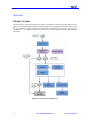
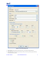
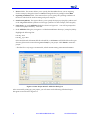
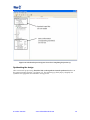
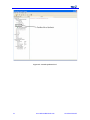
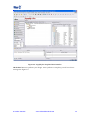
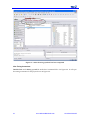
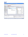
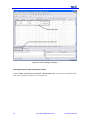
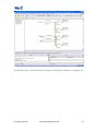
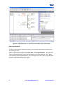
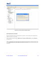
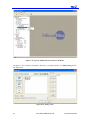
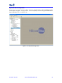
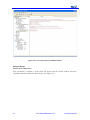
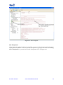
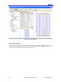
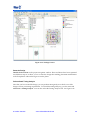
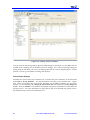
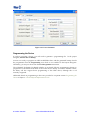
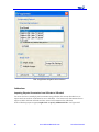
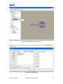
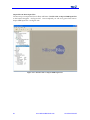
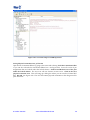
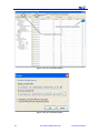
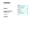
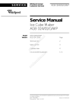
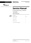
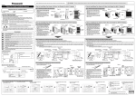
iCEcube2 Tutorial
v1.0 – May 2010
Copyright Information
Copyright ©2008-20010 SiliconBlue Technologies Corporation. All rights reserved. SiliconBlue,
iCEcube, iCEcube2, iCE65, mobileFPGA, are trademarks of SiliconBlue Technologies
Corporation. Magma and Blast FPGA are trademarks Magma Design Automation, Inc. Synopsys
and Synplify Pro are trademarks of Synopsys, Inc. All other trademarks are the property of their
prospective owners. All specifications are subject to change without notice.
Notice of Disclaimer: This software is provided to you "as-is," without any express or implied
warranty.
Contact Information
SiliconBlue Technologies Corporation
3255-7 Scott Blvd., Suite 101
Santa Clara, CA 95054
Tel: (408) 727-6101
Fax: (408) 727-6085
[email protected]
Revision History
The following table lists the revision history of this document.
Version
1.0
Revision
Release iCEcube2 2010.03
iCecube2 Tutorial
www.SiliconBlueTech.com
2
3
www.SiliconBlueTech.com
iCecube2 Tutorial
Preface
About this Document
The iCEcube2™ Tutorial takes the user through the iCEcube2 development tools step-by-step
using a sample design. After using the tutorial, the user will be able to set-up a project, compile a
design, and run different analysis tools such as the static timing analyzer and power estimator
tools.
For information on the Synopsys Synplify Pro software, please refer to the Synplify Pro
documentation provided in the synpro/doc directory in the iCEcube2 software installation
(<icecube2_install_dir>/synpro/doc), and on the SiliconBlue website.
For detailed information of the iCEcube2 development tools, please refer to the iCEcube2 User
Guide.
Software Version
This tutorial documents the features of iCecube2 Software Version 2010.03
For more information about acquiring the iCecube2 software, please visit the SiliconBlue website:
http://www.siliconbluetech.com.
Platform Requirements
The iCecube2 software can be installed on a platform satisfying the following minimum
requirements.
A Pentium 4 computer (500 MHz) with 512 MB of RAM, running one of the following operating
systems:
•
Windows XP Professional
•
Windows Vista
•
Red Hat Enterprise Linux WS v4.0
Programming Hardware
There are three ways to program iCE FPGA devices:
•
A third party programmer, using the programming files generated by the iCecube2
Physical Implementation Tools. Consult the third party programmer user manual for
instructions.
•
The iCEman Evaluation Board, which not only serves as a vehicle to evaluate iCE FPGAs,
but also includes an integrated device programmer. This programmer can be used to
program devices on the iCEman board, or it can be used to program devices in a target
system. Please contact SiliconBlue Technologies for additional information on the
iCEman Evaluation Board.
•
Digilent USB cables
iCecube2 Tutorial
www.SiliconBlueTech.com
4
Overview
iCEcube2 Tool Suite
The figure below depicts the design flow using the iCEcube2 Tool Suite. The components in blue
signify functionality supported by SiliconBlue Technologies’ proprietary iCEcube2 software, and
the components in purple indicate the functionality supported by Synopsys’ Synplify Pro
synthesis tools. The iCEcube2 software and Synopsys software together constitute the iCEcube2
Tool Suite.
Figure 0-1: The iCEcube2 Design Flow
5
www.SiliconBlueTech.com
iCecube2 Tutorial
Design Flow
The following steps provide an overview of the design flow using the iCEcube2 Tool Suite.
1. Create a new project in the iCEcube2 Project Navigator and specify a target device and its
operating conditions. Add your HDL (Verilog or VHDL) design files and your Constraint
files to the project.
2.
Synthesize your design using the Synplify Pro design software. This software has been
provided as part of the iCEcube2 Tool Suite, and can be invoked from the iCEcube2 Project
Navigator. Within the Synopsys design environment, assign your Logic Synthesis, Timing
and Pin constraints.
3.
Perform Placement and Routing using the iCEcube2 place and route tools. iCEcube2 also
supports physical implementation tools such as floor planning, allowing users to manually
place logic cells and IOs.
4.
Perform timing simulation of your design using an industry-standard HDL simulation tool.
The files necessary for simulation are automatically generated by the iCEcube2 Physical
Implementation tools, after the routing phase.
5.
Perform Static Timing Analysis using the iCEcube2 static timing analyzer.
6.
Generate the device programming and configuration files from the iCEcube2 Physical
Implementation tools.
7.
Program your device using the device programming hardware provided by Silicon Blue
Technologies.
Tutorial
This chapter provides a brief introduction to the iCEcube2 design flow. The goal of this chapter is
to familiarize the user with the fundamental steps needed to create a design project, synthesize
and implement the design, generate the necessary device configuration files, and program the
target device.
Detailed information on tool features and usage is provided in subsequent chapters.
Creating a Project
Starting the iCEcube2 software for the first time, you will see the following interface shown in
Figure 2-1.
iCecube2 Tutorial
www.SiliconBlueTech.com
6
Figure 0-1 : Create a New Project
The first step is to create a new design project and add the appropriate design files to your
project. You can create a new project by either selecting File>New Project from the iCEcube2
menu, or by clicking the Create a New Project icon as seen in Figure 2-1. The New Project
Wizard GUI is displayed in Figure 2-2.
7
www.SiliconBlueTech.com
iCecube2 Tutorial
Figure 0-2 : New Project Setup Form
1.
Project Name Field: Specify a project name (quick_start) in the Project Name field.
2.
Project Directory Field: Specify any directory where you want to place the project directory
in the Project Directory field.
iCecube2 Tutorial
www.SiliconBlueTech.com
8
3.
Device Fields: This section allows you to specify the SiliconBlue device you are targeting.
For this example, change the Device to L04 and change the device package to the CB284.
4.
Operating Condition Fields: This section allows you to specify the operating conditions of
the device which will be used for timing and power analysis.
5. Start From Synthesis: This option allows you to specify the Synopsys Synplify synthesis tool
or the Magma BlastFPGA synthesis tool for logic synthesis. For this example, select Synplify.
6. Click Next to go to the Add Files dialog box shown in Figure 2-3. You will be prompted to
create a new project directory. Click Yes.
7. In the Add Files dialog box, navigate to: <iCEcube2 installation directory>/examples/blinky
Highlight the following files:
blinky.vhd
blinky_syn.sdc*
Select each file and click >> to add the selected file, or click >>> to add all the files in the open
directory (files can be removed using << and <<<) to your project. Click Finish to create the
project.
* The SDC file is a Synopsys constraint file, which contains timing constraint information.
Figure 0-3: New Project Wizard – Add Files dialog box
After successfully setting-up your project, you will return to the following iCEcube2 Project
Navigator screen shown in Figure 2-4.
9
www.SiliconBlueTech.com
iCecube2 Tutorial
Figure 0-4: iCEcube2 Project Navigator View after Completing Project Set-up
Synthesizing the design
After a successful project setup, Double-Click on the Synthesis Launch Synthesis Tool icon in
the project navigator window. See Figure 2-5. This will bring-up the Synopsys Synplify Pro
synthesis tool’s graphical user interface. See Figure 2-6.
iCecube2 Tutorial
www.SiliconBlueTech.com
10
Figure 2-5 : Launch Synthesis Tool
11
www.SiliconBlueTech.com
iCecube2 Tutorial
Figure 2-6 : Synplify Pro Graphical User Interface
Hit the Run Button to synthesis your design. Once synthesis is complete, you will see a Done
message. See Figure 2-7.
iCecube2 Tutorial
www.SiliconBlueTech.com
12
Figure 2-7 : Status showing synthesis has been completed
View Timing Constraints
Double Click on the blinky_syn.sdc file under the Constraint folder. See Figure 2-8. It will open
the timing constraints for the project shown in Figure 2-9.
13
www.SiliconBlueTech.com
iCecube2 Tutorial
Figure 2-8 : Open the SDC file to View Timing Constraints
iCecube2 Tutorial
www.SiliconBlueTech.com
14
Figure 2-9 : View Timing Constraints
Viewing Hierarchical View of Synthesis Results
Under the HDL-Analyst menu, Select RTL > Hierarchical View. You will see a hierarchical RTL
view of the design just synthesized. See Figure 2-10.
15
www.SiliconBlueTech.com
iCecube2 Tutorial
Figure 2-10 : Hierarchical RTL View in HDL Analyst
If you double click on one of the blocks, it will take you to the RTL for that block. See Figure 2-11.
iCecube2 Tutorial
www.SiliconBlueTech.com
16
Figure 2-11 : Double-clicking on a block will reveal its HDL code in HDL Analyst
Select Implementation
In order to ensure that the synthesized design can be successfully imported into iCEcube2, exit
the Synplify Pro GUI.
Return to the iCEcube2 Navigator and Double-click on Select Implementation. See Figure 2-10.
This will tell iCEcube2 which synthesis implementation to process for place and route. If you
have different synthesis implementations, you will be able to select the synthesis implementation
you wish to place and route. Since we only have one implementation, select OK when the Select
Synthesis Implementation dialog box appears.
17
www.SiliconBlueTech.com
iCecube2 Tutorial
Figure 2-12 : Select Synthesis Implementation
Importing Physical Constraints
Physical constraints such as pin assignments are stored in a .PCF file (Physical Constraint File).
Add the .PCF file to your project.
In the iCEcube2 Project Navigator, Right Click on Specify Additional Files. Select Add Files…
See Figure 2-13.
Note: For information on importing physical constraints from iCEcube to iCEcube2, please refer
to the Importing Physical Constraints from iCEcube to iCEcube2 section at the end of this quick
start guide.
iCecube2 Tutorial
www.SiliconBlueTech.com
18
Figure 2-13 : Specify Additional Files for Place and Route
Navigate to the <iCEcube2 Installation Directory>/examples/blinky and Add blinky.pcf file.
See Figure 2-14.
Figure 2-14 : Add .pcf file
19
www.SiliconBlueTech.com
iCecube2 Tutorial
Import Place & Route Input Files
The next step is to import the files for Place and Route. Double-click on Import P&R Input Files
in the Project Navigator. See Figure 2-15. Once completed you will see a green check next to
Import P&R Input Files. See Figure 2-16.
Figure 2-15 : Import P&R Input files
iCecube2 Tutorial
www.SiliconBlueTech.com
20
Figure 2-16: Successful Import of P&R Input Files
Place the Design
Double-click on Run Placer
Once placement is complete, a green check will appear and the Output window will show
information about the placement of the design. See Figure 2-17.
21
www.SiliconBlueTech.com
iCecube2 Tutorial
Figure 2-17 : Place complete
View Floorplanner
At this point, since placement has been completed, you can view the placement of the design by
opening the Floorplanner. You can open the Floorplanner by going to the menu and selecting
Tool > Floorplanner or you can also select the Floorplanner Icon. See Figure 2-18.
iCecube2 Tutorial
www.SiliconBlueTech.com
22
Figure 2-18 – Floorplanner
View the Package Viewer
You can also see how pins were placed for your design by selecting the Package Viewer. You can
select the package viewer by going to the menu and selecting Tool >> Package Viewer or you
can also select the Package Vierwer Icon. See Figure 2-19.
23
www.SiliconBlueTech.com
iCecube2 Tutorial
Figure 2-19 : Package Viewer
Route the Design
Double-click on Route in the project navigation window. Place and Route have been separated
into different steps as to allow you to re-route the design after making placement modifications
in the floorplanner without having to re-run the placer.
Perform Static Timing Analysis
Now that you have routed the design, you can perform timing analysis to check to see if the
design is meets your timing requirements. To launch the timing analyzer, go to the menu and
select Tool > Timing Analysis. You can also select the Timing Analysis Icon. See Figure 2-22.
iCecube2 Tutorial
www.SiliconBlueTech.com
24
Figure 2-22 : Timing Analysis Summary
You can see from the timing analysis that our 1MHz design is running at over 100 MHz and our
32 MHz clock is running at over 70 MHz (worst case timing). If we were not meeting timing, the
timing analyzer will allow you to see your failing paths and do a more in-depth analysis. For this
tutorial, we won’t go into details on timing slack analysis.
Perform Power Analysis
iCEcube2 also comes with power estimator tool. To launch the power estimator, to the menu and
select Tool >> Power Estimator. You can alternatively select the power estimator icon. Figure
2-23. There are multiple tabs in the Power Estimator tool including Summary, IO, and Clock
Domain. On the Summary tab, change the Core Vdd to 1.0V and make sure all IO voltages are
at 2.5V. Then hit calculate. The estimator will update with power information for both static and
dynamic power. For more information on using the IO and Clock Domain tabs, please refer to
the detailed section on the Power Estimator tool.
25
www.SiliconBlueTech.com
iCecube2 Tutorial
Figure 2-23 : Power Estimator
Programming the Device
In order to program a device, you will need to generate a programming file. In the project
navigator, double click on Bitmap.
You are now ready to program an iCE65 mobileFPGA deice with the generated bitmap. Invoke
the programmer from the Programming icon which is now enabled in the Project Navigator.
Alternately, you may invoke it from the Tool>Programmer menu item.
The iCEman65 Evaluation Kit Board includes an on-board USB 2.0 programming solution to
program the on-board SPI serial Flash or the iCE65 device directly. In a future iCEcube release,
the utility will also support direct programming of the iCE65 device, although this is not
currently supported.
Additional details on programming a device are provided in a separate section Programming the
Device in Chapter 5 iCEcube Physical Implementation Tools.
iCecube2 Tutorial
www.SiliconBlueTech.com
26
2-24 : Programmer Graphical User Interface
Addendum:
Importing Physical Constraints from iCEcube to iCEcube2
For users who have created physical constraints using iCEcube, this section describes how to
import and convert those constraints for use in iCEcube2. This section will demonstrate how to
import a .MTCL file from iCEcube and save it into .PCF format used in iCEcube2.
In the iCEcube2 project navigator, Right-click on Specify Additional Files. See Figure 2-25
27
www.SiliconBlueTech.com
iCecube2 Tutorial
Figure 2-25 : Add additional constraint file
Navigate to the <iCEcube2 Installation Directory>/examples/blinky and Add blinky.mtcl file.
See Figure 2-26.
Figure 2-26 : Add .mtcl file
iCecube2 Tutorial
www.SiliconBlueTech.com
28
Import Place & Route Input Files
The next step is to import the files for Place and Route. Double-click on Import P&R Input Files
in the Project Navigator. See Figure 2-27. Once completed you will see a green check next to
Import P&R Input Files. See Figure 2-28.
Figure 2-27 : Double-click on Import P&R Input files
29
www.SiliconBlueTech.com
iCecube2 Tutorial
Figure 2-28: Successful Import of P&R Input Files
Saving Physical Constraints into .pcf Format
Open the Pin Constraints Editor by going to the menu and selecting Tool>Pin Constraints Editor
or you can also select the Pin Constraints Editor Icon. See Figure 2-29. You will se a list of pin
assignments that are Locked under the locked column. Uncheck and Recheck one of the pins
under the locked column. The save icon will now become an active icon. Click on the Save
physical constraints icon. This will bring up a dialog box where you can save the CLB and PCF
files. Hit OK. See Figure 2-30. The .PCF file contain physical constraints in the design used for
place and route.
iCecube2 Tutorial
www.SiliconBlueTech.com
30
Figure 2-29 : Pin Constraints Editor.
Figure 2-30 : Pin Constraints Editor.
31
www.SiliconBlueTech.com
iCecube2 Tutorial