1
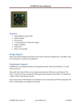
Antti-Brain Issue 5 January 2009 FPGA-STAMP http://www.antti-brain.com Revised on January 31, 2009 Editorial New year is going to be even more work. The issue is still far away from the desired level of editorial workmanship. Antti Lukats [email protected] http://groups.google.com/group/antti-brain Antti-Brain 1/2009 Page 2 http://www.antti-brain.com Cover Story – FPGA Stamp I have an unpublished/unfinished book titled “My First Flash FPGA”, well highlighted there was Lattice XP device. The FPGA stamp is however based on Actel ProAsic3. The reasons are non technical, the STAMP60 (A3P060 based Stamp) is very low cost FPGA module. Specially designed to the most pricecritical use. STAMP60 User Manual is preparation so I will not talk much about it here. Here is a snapshot of CoreABC (Actel small soft MCU) running simulation in Xilinx ISIM. CoreABC can nicely fit into A3P060. STAMP60 PCB revision A first testing. Strange thing, initially I connected only 1 GND in the JTAG cable header (lower row, right most pin in the 10 pin header). The JTAG programming worked, but only when pushing rather hard with the finger over the pins. Without that the JTAG scan returned wrong readback values. Actel JTAG cable has 2 GND pins, both are grounded on the other side (in the programmer). So the skin resistance should not matter? Well I measured it all over, all solder contacts are OK. But only after connecting the other GND pins also to GND (the short blue wire) JTAG started to work without my finger holding it tight. Cover photo: the self-made capacitor tunes the pin-oscillator to about 3 times lower, the LED blink rate changes about that much. Antti-Brain 1/2009 Page 3 http://www.antti-brain.com Short Stories Spartan/Virtex6 Good One package is available for most S-6 (except 3 smallest) Only one TQFP package available Smallest package 13x13 (no 8x8 mm Package) AES Encryption only available in the largest S-6 AES E-fuse only available for V-6 not for S-6 Bad Also there is no info about hard-core CPU’s any more. No ARM in S-6, no PPC in V-6. And no USB either. So some rumors where just rumors. Xilinx did obtain ARM license when they purchased Triscend, but they have not been able to use it. The hope it appears in S-6 proved false. FX2 Adapter for Xilinx Boards You have a Spartan-3A Starterkit? Or some other Xilinx board with this FX2 style extension connector? And nothing to connect to it? Pictured is simple adapter that brings out most of the I/O on 40 Pin header (compatible to the header found on Silicon Blue iceMAN65!). As an extra bonus there is micro-SD slot, and user JTAG header. And jumper to “break the JTAG chain”. When the jumper is installed the onboard JTAG header is routed via the adapter and the pin header can be used JTAG master port. And you can use your S3A board as Xilinx USB JTAG Cable Antti-Brain 1/2009 Page 4 http://www.antti-brain.com SiliconBlues TI USB !? I would really think twice before touching TI USB FS chips (TUSB3410, etc..), as they are rather old all, but for a project I was asked to lend a helping hand, so here are some notes. Simple task: take TI source code, compile it, and make really minor change. Ok, first thing you need IAR compiler. Ok, now trying to open the project file, FAIL, the old project files cannot be imported. Ok, creating a new project. Adding source files. Trying to compile. First thing it claims that the code needs IAR specific stuff, but hey, I am using IAR Compiler? Ok adding the DEFINE statement so the source code would detect the IAR. Now what? #pragma overlay=off Gives error god, the code is SO OLD, that neither the project files work, not the compiler default defines, not the pragma’s. Oh no, it is getting even worse Error[Pe020]: identifier "code" is undefined C:\prj\usb\ti\all\Dfw\inc\RtkApi.h 83 Ok, this should be some setting somewhere what was lost with the project file, I assume. Giving up on the IAR, trying the HID demo code which includes a Keil project file, double click, press F7, build… complete, 0 error’s. Done! Installing “header generator” utilities. Oh NO. DOS programs! Really, dated 2004, old style DOS programs. Documentation is some one page of ASCII text. Downloading all the accessible files related to USB from TI, trying to find out how to use the GPIO lines on the TUSB3410 while using the default VCP drivers. But, failing, it seems really not be possible, so the chip has 4 GPIO lines, but in order to use them, one really needs to develop complete own firmware. Actel CLKDLY Actel CCC circuits can implement a delay where the delay is set by 5 pins of the CLK_DLY primitive. So I created a special design with this delay element, and connected the delay select wires to switches to I/O pads (that have switches on the PCB). And guess what? Actel Designer tells me that those pins need to be driven by VCC or GND. But eh if that so, why make them as wires? If those wires are optimized away to become a configuration bit setting, it would be better to use a parameter, not HDL ports for them. Or at least describe them properly in the documentation so it is clear that dynamic change of the delay is not possible. Error: CMP403: PLL configuration bit 'Inst1:S_DLYHC1' must be driven by VCC or GND. So my nice demo design is not at all possible. Antti-Brain 1/2009 Page 5 http://www.antti-brain.com Actel CoreABC!? I was about to say nice things about the “smart design” in Actel Libero 8.5, but then I wanted to make a simplest demo with CoreABC, it should be very simple? So in the IP Catalog I click on CoreABC, hm.. it asks for the Profile for CoreConsole! How come, CoreConsole is replaced by Smart Design, so why can’t I just use the CoreABC? I try Core8051, this works nicely. Ok, I download CoreConsole, I get license for it, I install the license. I try again adding CoreABC to the smart design. Ok, it works. I add the connections, save the file. But then it complains when generating the design. I open the design and part of the connections are just gone. I do them again, but they vanish again. So what’s up? I close the Project and open it again. Now I get a warning that I need to upgrade the CoreConsole project to SmartDesign, good! This is what needs to be done, I think.. But wrong all I get is error saying that the upgrade of CoreABC is not supported! Ok, maybe I did something wrong. I try hard to find some information or example how to use CoreABC with smart design. On the Fusion info pages I find a link tagged “new” that has full project including CoreABC for Fusion Starter-kit. Good, this must work correctly. You think it does? No way, same error during upgrade attempt. So it seems that I have to wait for Libero 8.6, or 8.x or 9.x or forever. Now, please do not go saying I am stupid and should read more manuals, on Actel webpage on the Smart Design features page there is a screenshot from an Smart Design document that includes a CoreABC core, so it must be possible. But not with the latest Libero as it seems. I made one more attempt, I tried the Fusion CoreABC demo project from Actel website without modifications, and without an attempt to convert to smart design. I got as far as Actel Design selftermination… SOLVED – the issue is rather simple, the minimum number of APB slaves for the smart design based flow is 2! Any attempt to generate a system with only one APB peripheral (or only one APB slot defined) will result in failure. Xilinx XC9500 Talked a fellow engineer yesterday, he had a small change to make to an old existing and working XC9500 CPLD Design. It all used to work with ISE 8.1 but with ISE 10.1 it doesn’t fit any more (also before doing any changes). This lines up with my own experience, CPLD design done with 6.3 did not work with 8.1 tools. As there has been no new developments on Xilinx CPLD’s for a very long time they should be considered really as DO NOT USE. Antti-Brain 1/2009 Page 6 http://www.antti-brain.com Controller Corner SiLabs MCU’s Part III Still not the easy how-to getting started guide! Updater working! Getting my old F326 HID update solution wasn’t actually that hard. After fixing the minor source code changes needed it looked like the solution is working. But I had strange issues, it seemed that my PC host software was doing something really bad as I was never able to start it more than just a few times, until weird things started to happen. So what happened was that USB HID devices attached did keep working (USB mouse), and USBview did see attached devices and also devices newly plugged in as well. But my software did not see any USB HID devices, not even the mouse that was definitely still working. As a side effect Device Manager window was completely blank. Just empty! I tried look if I maybe need checking USB HID devices in my software to solve the problem. But, well if we see something strange we should investigate. I had also notices that windows dcom service is eating memory, after each restart it did eat memory up until about 1.3GByte within 15 minutes. Sure Windows Vista is a bad, but it sounded a little bit too much for the O/S to just consume. Well all MS security was activated and monitoring software threats. So much about it, I installed another anti-virus and got one nasty one killed quickly. After that I uninstalled all the MS security scanner and stuff. And the USB HID problems did go away. Ok, now I had it all ready to go. But I needed something to download into the target device for testing. I had old LED blink binary that I had tested on F326, but it had wrong LED assignment so was not directly useable. It was also made with IAR tools. So I start another SiLabs IDE project, add the sources, change the toolchain to IAR, and well, I had again fix the linker script for syntax errors, but after that it compiled. But how to get binary file? Should I specify custom executable for external hex file generator and use hex2bin? Reading IAR XLINK manual. In SiLabs IDE toolchain integration dialog I just change the –Fxxx option to –Fraw-binary. Running build, checking files, yes we have a binary! Does it work? I launch my PC side application, select the “blink.bin” and click download. Done. Another click launches the downloaded test program that should blink the LED using timer interrupts. And yes, the LED does blink! Time for standalone check, does the application start when starting directly? Hum.. something still not right, the LED is dimmed, not off not on and not blinking. Ah, I got it, I had the watchdog disable in the start of the USB firmware update function, so when the user application is starting directly then watchdog is still enabled what will cause repeat resets. Recompiling the user application, using my firmware updater, testing direct launch, and yes, this time all works perfectly, the LED blinks. This is very good as it also test that the interrupt vector redirect is all working, because the use application uses customized interrupt vector table located at 0x1000 in the instruction space. The firmware update function is not using interrupt so all interrupts including USB interrupt are directly jumping to the new table (there are no conditional checks needed). Antti-Brain 1/2009 Page 7 http://www.antti-brain.com I2C Bus Testing Ok, I have the firmware updater working, so I need to test the rest of the functions. The motion sensor is connected to the I2C bus pins. So let’s take this as next. I take an example source from SiLabs examples. Changing the pin mapping and crossbar settings. Download, run, LED goes off. Hum.. but what did the code do? At least it doesn’t work, well it’s not adopted to the device address yet. But after doing it, there is still some error. It seems that SCL is kept low. Ok, adding external pull-up resistor on SCL too. <skipped lots of troubleshooting> Fixed: the CMA3000 on the board where I did I2C testing was simply dead. So my code worked ok, as soon as I connected a known good device to the MCU pins. Antti-Brain 1/2009 Page 8 http://www.antti-brain.com Silicon Blue FPGA Part II Where is part I you may ask, well look back into the first issue, and consider that part I, so this is part II. SB Tools December 2008 While the new releases are much better than the summer 2008 release, there are still things that buggy me: 1. There is not a single example with full files (not a single project file) 2. The SPI flashing is still in its infantry Those issues are not so problematic, the project file can be created from scratch, and then there are no problems generating the programming bitstream. Now, after installing the December 2008 tools, I also did run the USB driver install with “modify” setting. I hoped it does all that is needed. Well the programming did seem to work after that, SB tools did not say any errors, just “programmed ok”. But the FPGA was able to configure itself also after an chip erase! When I found that, then I did full uninstall and fresh install cycle. After that erased flash no longer configured the FPGA, so I hoped the writing may also work. And it did work ok. IMPORTANT: when installing SBT tools, ALWAYS do a full uninstall and fresh install of the USB drivers! My first SiBlue Design The making of this board was a little bit described in the first issue. Unfortunately the first prototype PCB happened to have several minor issues: the CMA3000 sensor pads wrong, and I had designed the board with 1.2V LDO in SOT-23-3 package, but then I could not find any IC in that package, only in SOT23-5. So the PCB did lay around a long time ago, until I finally soldered the SOT23-5 LDO and made small wire fix to make it adapt the SOT23-3 footprint. PCB bottom the SO23-5 work-around wires. Added 6 pin header for SPI flash. Antti-Brain 1/2009 Page 9 http://www.antti-brain.com Test system components: SD-microSD adapter, micro-UD-ice, 6Pin microSD adapter, micro-UD SPI card. For easy testing I soldered wires to the SPI flash pads on the PCB, and used a micro-SD adapter to insert an micro-UD SPI Flash card. The micro-UD Flash card was programmed with the SB programming software and iceMAN65 evaluation board. (Please see issue 2 for the setup). Now here the L04 micro-UD board is already working, it is deriving power from the SD slot of my notebook, at front you see the micro-UD SPI Flash card. This is prototyping setup only, the SPI flash should be soldered directly onto the board later. The LED that is on, is not POWER LED, it is controlled by the FPGA. Antti-Brain 1/2009 Page 10 http://www.antti-brain.com SiLabs Radio Part II <continued> Writing bit bang SPI routines for the Si4721 in SPI mode. All well, I get also CTS (clear to send) status bit read back work OK. That is status is 0x00 and then it goes 0x80 (ready). But now let’s try read the device Revision? I issue POWERUP command, then DEV_ID command, then read response bytes. All 0’s, that not right. Looking example code, ah the POWERUP command has special parameter for the QUERY, I had placed the parameter as command byte, ok testing again.. timeout! Time to think. Maybe it needs reference clock to be present? Ok, adding clock, the wires I had already added so I only needed to route clock to the RCLK pin. One VHDL assignment, running Xilinx implementation, copy file to micro-SD insert it to DS, run XSVF player, done. Testing, no difference. Hum, right I need to enable the clock output first, changing code, testing, no difference. Maybe the 4.19 MHz clock is not suitable? Well most any clock up to 40Mhz should be ok, but well all the example code seems to be for 32KHz clock, so I think maybe I try too with that default. So adding prescaler, updating CPLD, testing, no difference. Timeout. RTFM. After some more struggle, found the proper power up and init sequence. Well, I was initially working based on the information I gathered from the SiLabs reference source, but I had not the PDF supplementary documentation. After reading that, and doing the right commands in the correct sequence it all worked. Well the REVID response did come properly, I still have minor code to add to get the actual functions tested. Antti-Brain 1/2009 Page 11 http://www.antti-brain.com CAD Libraries Doing some research how good the CAD libraries from different vendors really are. Microchip Has some special format that can be converted to multiply CAD formats. Nice idea but the conversion process is slow hand-work and the libraries do not seem to be very good in the converted native format also. But at least the exports are possible. ADI It was nice to see ADI is offering both Schematic and Footprint libraries for Altium directly. So I downloaded 2 zip files. And well got a small bad surprise, the footprint library included 181 another zip files, so they have to be unzipped another time. The Schematic library archive was little better, the files inside the zip are not zipped another time. Wrong, the symbol archive contained total 9373, both zip archives as plain library files. Ok, I am creating a new integrated library project and will be adding ADI library components to it. Let’s see if the parts I am interested are included. Doesn’t look too good, I created a new schematic library ADI_CDC, and wanted to add all current ADI CDC(Capacitance Digital Converter) devices to it, but ADI’s online library only included 1 of the 10 devices. Let’s see if we have the matching footprint. AD7142 (the only CDC device included) has package code CP-32-2, but this is not included with ADI PCB Footprints, only CP-32-1 is available. But with this type of packages it is very important to have really right footprint! And so it is, CP-32-1 does not have the exposed pad. So from the first type of devices checked in ADI online CAD libraries, 10 out of 10 failed. Ok, I look little deeper, the all-in-one library download is missing some components that are available as single download. But as example for AD7148 there no schematic component download, and for most others there is no PCB library component that could be imported into Altium without double conversion process. The schematic library components, they are of course correct, but not done the way I would like it, as example if I2C pins are one to left one to right side of the component? If analog and digital pins are grouped together? If NC pins is drawn as bi-dir I/O? Antti-Brain 1/2009 Page 12 http://www.antti-brain.com Single Sided Simple electronics die hard. FT232RL A FT232RL usb-uart adapter I made long time ago. Single sided PCB. Sipsik™ header. It mates to the FPGA Stamp proto break out from the cover. (The RX/TX wires on the cover are not connected, I soldered those wires later). Antti-Brain 1/2009 Page 13 http://www.antti-brain.com LOL I am still laughing, thank you ADI, brilliant! Here is why I added the LOL section: RAQ FAQ’s are so common, so ADI decided to introduce RAQ – Rarely Asked Questions link to their product documentation pages. It maybe not so much of novelty, but it made me laugh. Silicon Blue LED is ON Another case where I really did make loud noise(a HAA), well when the LED was on first time. The story and HAA place can be found in the “Silicon Blue Part II” in this issue. Antti-Brain 1/2009 Page 14 http://www.antti-brain.com References http://www.trioflex.com Instead of adding the URL links at the end of each issue, I will be adding them to the Trioflex online link collection, so they can be updated more frequently. Antti-Brain 1/2009 Page 15