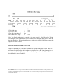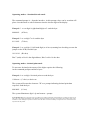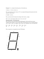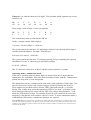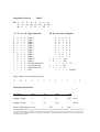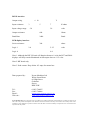
1
Nexus
LED Driver and Interface Module. RS232 Interface.
Machines
User Manual Ver 1.0
_____________________________________________________________
BIF-RL
System Description
BIF-RL is an interface and control PCB that takes instructions in single byte RS232
format and decodes them into commands and data for the B57L and B100L integrated
LED displays with driver. Up to 3 master and 3 slave LED display boards (total 12 seven
segment displays) can be controlled from one BIF-RL interface.The LED driver protocol
is that of a synchronous serial peripheral (SPI) bus with the data clocked on the rising
edge. The interface uses chip enable, data and clock to communicate with the MM5450
display driver IC.
The interface board communicates with the host (eg PC or microcontroller with RS232
port) via a two way (transmit and receive) serial link which is compliant with the
RS232C standard. The host sends 1 byte commands/data to the interface, the interface
acknowledges by returning a single status byte that instructs the host of the next byte to
send. Decoded, non decoded, decimal point control and annunciator modes are supported.
Digit address and data byte organisation
The unit can drive up to 3 master boards and three slave boards making a total of 12
seven segment displays. Digit 0 is the right hand digit, digit 11 is the left hand digit
(assuming a 12 digit display). In standard mode the unit will decode the byte sent into a
hexadecimal or code B character providing the digit address portion of the byte (top
nibble)is below 12. Addresses above 12 access the special command modes that allow
non decode mode, control of the decimal points , control of the annunciator outputs and
resetting of the displays. Note that if digit addresses are accessed that do not have a
physical display connected then the data is simply lost. Decode mode requires only a
single byte, the other modes requires 2 or 3 bytes to be sent before the operation is
complete. The RS232 data is constucted as shown below. Table 1 shows the action taken
by the BIF interface verses hex input value.
D7
D6
D5
D4
Digit address/command
D3
D2
D1
D0
Digit data/control data
Nexus Machines ltd reserves the right to alter or withdraw the product specification and characteristics without prior notice at any
time in line with product development. Nexus Machines ltd sole and exclusive warranty is that stated in the warranty article of the
conditions of sale. Although every effort is made to ensure this data is accurate no liability is accepted for errors or ommisions that
may affect the end product.
RS232 Interface Protocol
The RS232 interface operates at a fixed rate of 2400 baud 8 bits with 1 stop and 1 start
for both the transmit and receive lines. Levels are standard RS232 normal polarity (ie line
rests at -10volts). A command can only be sent once the host has received the appropriate
cursor for the command in hand. If data is sent whilst the previous command is still
executing then it will be ignored. An RS232 status bit is available that is set to logic 0
(+10 volts on RS232 line) whilst the system is busy and logic 1(-10 volts on RS232 line)
when it is available to receive commands.
Note:- RS232 data is sent LSB first for this interface.
The RS232 port is connected to the 6 way 0.1 inch pitch Molex connector on the right
hand end of the interface board. Connections are as follows
Pin Number
1
2
3
4
5
6
Function
0 volts (note RS232 is non isolated)
No connection
Ready to receive
Data to host (from interface board)
No connection
Data from host (to interface board)
Table 1
Power connections
The power is applied to the board through a two way 0.1 inch pitch header. Polarity is
marked and a diode protects the interface from reverse polarity. IT DOES NOT
PROTECT THE LED DISPLAY/DRIVER - The B100/B57 displays and other third
party displays may be damaged by reverse connection or by "hot insertion" therefore it is
advisable to check the supply polarity before connection. The interface has its own +5
volt regulator on board to provide the required internal +5 volt line. External LED
displays should not draw more than 0.75 amps from each LED headers +12 volt line. The
user must ensure the supply voltage falls within that laid out in the data sheet
specifications otherwise damage and/or malfunction can occur. It is advisable to provide
reservoir capacitance for the displays especially if the power supply is located remotely
from the LED's. The B57 and B100 displays have on board resevoir capacitors. If a third
party display is being driven then a reservoir capacitance of 47uf per digit should be
provided local to the LED display.
Note that if 12 digits are being driven by the BIF interface then the power supply will be
required to source up to 2.0 amps (assuming all LED's on and 20mA per segment) Ensure
that the cables are of adequate cross section for the current, and are connected to the
power supply in a star point ground configuration to minimise problems with transient or
loop currents. Note it is often power supply cables that can be a source of EM
interference due to the large current spikes when the LED's change state. Good grounding
and decoupling are essential.
Nexus Machines ltd reserves the right to alter or withdraw the product specification and characteristics without prior notice at any
time in line with product development. Nexus Machines ltd sole and exclusive warranty is that stated in the warranty article of the
conditions of sale. Although every effort is made to ensure this data is accurate no liability is accepted for errors or ommisions that
may affect the end product.
LED Display/Driver Interface connections
Three 5 pin 0.1 inch pitch molex style connectors provide the interface to the B100/B57
displays. Note that although usually connected to these displays this interface board will
drive a third party display providing the MM5450 driver chip is used on the board. The
pin out is as follows:
Connector 1 - Right hand connector is for digit adresses 0 to 3
Connector 2 - Middle connector is for digit addresses 8 to 11
Connector 3 - Left hand connector is for digit addresses 4 to 7
All connectors have the same pin out:
Pin Number
Function
1
2
3
4
5
Chip enable (active low)
Data
Clock (rising edge active)
0 volts
+12 volt (nominal) from power header
Note the clock line,data line and chip enable line all have series resistors of 330 ohms
value. This is to provide a degree of protection against ESD discharge and accidental
shorting of active outputs. To be compatible with the B57L and B100L displays and to
limit EMC radiation from long lines the data rate has been kept around 10 k bits/sec. The
timing of the clock provides a 50us high pulse duration during data valid shift out. This,
combined with the software decoding and driving, limits the update rate of the displays
to 1 digit every 30ms or about 33 digit alterations per second for the standard decode
mode(in fact 4 digits are updated at once due to the nature of the driver chip but the
single byte protocol means only 1 digit can change at a time) . This should be fast enough
for most applications. Faster update rate versions are available. Contact the manufacturer
for details. (see appendix)
Nexus Machines ltd reserves the right to alter or withdraw the product specification and characteristics without prior notice at any
time in line with product development. Nexus Machines ltd sole and exclusive warranty is that stated in the warranty article of the
conditions of sale. Although every effort is made to ensure this data is accurate no liability is accepted for errors or ommisions that
may affect the end product.
Clock high time
Clock low time
CE to clk rising edge t3
Data stable before edge
Min
50 us
50 us
t1
t2
10 us
t4
10 us
Note: The first bit of the data is a start bit. It is always a logic 1. It is followed by 32 bits
containing the LED segment data, 2 bits of annunciator data and a final clock to latch the
data into the driver. The maximum frequency of the driver is 500 KHz. Please contact the
supplier for faster versions.
Power on initialisation and decode mode
On power up the device will send a command line prompt to the host system. This is a >
character and signifies the unit is ready to receive a command. The decode mode is
determined on power up by the setting of the jumper on the PCB. If this is changed it is
necessary to reset the system in order for the new setting to take effect. The standard
decode mode is shown in table 2.
Nexus Machines ltd reserves the right to alter or withdraw the product specification and characteristics without prior notice at any
time in line with product development. Nexus Machines ltd sole and exclusive warranty is that stated in the warranty article of the
conditions of sale. Although every effort is made to ensure this data is accurate no liability is accepted for errors or ommisions that
may affect the end product.
Operating modes. - Standard decode mode
The command prompt is > from the interface. At this prompt a byte can be sent that will
place a hexadecimal or code B character into the chosen digit on the display.
Example 1 - to set digit 0 (right hand digit) to 5 send the byte
00000101
(05 hex)
Example 2 - to set digit 7 to 9 send the byte
01111001
(79 hex)
Example 3 - to set digit 11 (left hand digit) to A hex (assuming hex decoding set onto the
jumper on the PCB) send the byte
10111010
(BA hex)
Bits 7 (msb) to bit 4 is the digit address, Bits 3 to bit 0 is the data
Operating modes - decimal point mode
To turn on a decimal point on any of the digits requires the following.
At the command prompt send these bytes.
Example 4 - to set digit 1 decimal point on send the byte
1100xxxx (Cx hex) x=don't care
The system will return the character "D" as a prompt indicating decimal point data
expected. Send the byte
00010001 (11 hex)
The system illuminates digit 1 dp and returns > prompt
Nexus Machines ltd reserves the right to alter or withdraw the product specification and characteristics without prior notice at any
time in line with product development. Nexus Machines ltd sole and exclusive warranty is that stated in the warranty article of the
conditions of sale. Although every effort is made to ensure this data is accurate no liability is accepted for errors or ommisions that
may affect the end product.
Example 5 - to set digit 6 decimal point to off send the byte
1100xxxx (Cx hex) x=don't care
The system will return the character "D" as a prompt indicating decimal point mode data
expected. Send the byte
01100000 (60 hex)
The system turns off decimal point on digit 6 and returns > prompt
Bits 7 to 4 are the digit dp address bit 0=1 for on 0 for off
Operating modes - no decode mode
The system can send each digit undecoded information. In this mode the user must
calculate which segment is to be on and which off and construct a byte of segment data to
send. A logic 1 turns on a segment a logic 0 turns it off. Segments to bits correspond thus:
Bit 7
Dp
Bit 6
G
Bit 5
F
Bit 4
E
Bit 3
D
Bit 2 Bit 1 Bit 0
C
B
A
These segments are arranged thus on the LED display.
Example 6 - to send the character S to digit 5. First calculate which segments are on and
which are off.
DP
off
G
on
F
on
E
off
D
on
C
on
B
off
A
on
Then assign a value of logic 1 to the on segments
DP
0
G
1
F
1
E
0
D
1
C
1
B
0
A
1
This is the binary value to send which is 6D hex
At the > prompt send the following byte
1101xxxx (Dx hex) where x = don't care
The system returns the character "N" indicating waiting for byte showing which digit to
send the undecoded data to. For digit 5 Send the byte
0101xxxx (5x) where x = don't care
The system returns the character "S" indicating waiting for byte containing the segment
information. For the "S" character just calculated send byte
01101101 (6D hex)
The "S" character will now be in digit 5 and the system returns the > prompt
Operating modes - annunciator mode
If the unit is operating with less than 4 digits (ie master board only 2 digits) then the
annunciators are unavailable. Each slave board contains a header with the 2 annunciators
pinned out along with +8 volts and ground.
The annunciator pins are constant current sinks with a sink capability of 20mA max. Care
must be taken not to connect any external voltages which may damage the driver IC.
These outputs are provided to drive discrete LED's connected from the + 8 volt line.
Ideally if the voltage drop across the annunciator LED's is less than 7 volts then a zener
diode should be connected in series with the LED. The voltage rating should be 7 volts
minus the LED forward voltage. For example if two leds were connected in series each
dropping 2 volts then the zener could be rated a 3.0 volts. To access annunciator mode a
command byte followed by a annunciator data byte are required.
Nexus Machines ltd reserves the right to alter or withdraw the product specification and characteristics without prior notice at any
time in line with product development. Nexus Machines ltd sole and exclusive warranty is that stated in the warranty article of the
conditions of sale. Although every effort is made to ensure this data is accurate no liability is accepted for errors or ommisions that
may affect the end product.
Example 7 - To turn on annunciator 1 on slave board 0 (digits 0 to 3)
At the command prompt send the byte
1110xxxx (Ex hex) where x = don't care
The system will respond with the character "A" as a prompt indicating waiting for
annunciator data. Send the byte
00010010 (12 hex)
The AN1 pin on slave board 0 will go high and the > prompt will follow
Example 8 - To turn off annunciator 0 on slave board 3 (digits 8 to 11)
At the command prompt send the byte
1110xxxx (Ex hex) where x = don't care
The system will respond with the character "A" as a prompt indicating waiting for
annunciator data. Send the byte
10010000 (90 hex)
The AN0 pin on slave board 3 will go low and the > prompt will follow
Bit 7 to 4 are the digit address of a digit on the board the annunciators are on. Bits 1 and 0
correspond to the annunciators 1 and 0.Note that the addresses can be a range and have
the same function.
Address 0 to 3 are for slave board 0 annunciators
Address 4 to 7 are for slave board 1 annunciators
Address 8 to 11 are for slave board 2 annunciators
Operating modes - Reset mode
If the system requires to be reset the following data byte should be sent at any of the
prompts. This clears all internal held data to 0.
11111111 (FF hex)
The sytem responds with the character "R" and then the > prompt.
Nexus Machines ltd reserves the right to alter or withdraw the product specification and characteristics without prior notice at any
time in line with product development. Nexus Machines ltd sole and exclusive warranty is that stated in the warranty article of the
conditions of sale. Although every effort is made to ensure this data is accurate no liability is accepted for errors or ommisions that
may affect the end product.
Single Byte Protocol
Bit 7
A3
Dp
6
A2
G
5
A1
F
-
Table 2
4 3
2 1 0
A0 D3 D2 D1 D0
E
D
C
B A
A3 A2 A1 A0 Digit addressed
0
0
0
0
0
0
0
0
1
1
1
1
1
1
1
1
0
0
0
0
1
1
1
1
0
0
0
0
1
1
1
1
0
0
1
1
0
0
1
1
0
0
1
1
0
0
1
1
0
1
0
1
0
1
0
1
0
1
0
1
0
1
0
1
D3 D2 D1 D0 Led Display
Digit 0
Digit 1
Digit 2
Digit 3
Digit 4
Digit 5
Digit 6
Digit 7
Digit 8
Digit 9
Digit 10
Digit 11
Decimal point cmd
No decode cmd
annunciator cmd
reset
0
0
0
0
0
0
0
0
1
1
1
1
0
0
0
0
0
0
1
1
1
1
0
0
1
1
0
0
1
1
0
0
1
1
0
0
0
1
0
1
0
1
0
1
0
1
A/H
b/E
0 0
d/P
E/1 1
0
1
1
1
1
1
1 0 1
1 1 0
1 1
0
1
2
3
4
5
6
7
8
9
C/L
F/blank
Digit Address versus display position.
11
10
9
8
7
6
5
4
3
2
1
0
Electrical Specification
Parameter
Min
Typ
Max
Units
Supply voltage
8
12
14
VDC note1
Supply Current
18
30
mA
Driven LED supply current
0.75
note 2
A
note 3
Nexus Machines ltd reserves the right to alter or withdraw the product specification and characteristics without prior notice at any
time in line with product development. Nexus Machines ltd sole and exclusive warranty is that stated in the warranty article of the
conditions of sale. Although every effort is made to ensure this data is accurate no liability is accepted for errors or ommisions that
may affect the end product.
RS232 interface
Output swing
Input resistance
+/- 10
3
Input voltage range
V
5
-30
7
K ohms
30
volts
Output resistance
600
Ohms
Baud Rate
2400
Baud
300
ohms
LED display interface
Series resistance
Logic 1
2.4
5.25
Logic 0
volts
0.8
Note 1 Although the BIF -RL unit will function down to 8 volts the B57 and B100
displays will only remain illuminated at full output down to 11.5 volts
Note 2 BIF board only
Note 3 Peak current. Keep below 0.5 amps for normal use
Data prepared by :
Nexus Machines Ltd
White Swan House
60 High Street
Godstone
Surrey
RH9 8LW
Tel :
Fax:
Email :
Web site :
01883 744455
01883 744466
[email protected]
www.nexus-machines.demon.co.uk
Nexus Machines ltd reserves the right to alter or withdraw the product specification and characteristics without prior notice at any
time in line with product development. Nexus Machines ltd sole and exclusive warranty is that stated in the warranty article of the
conditions of sale. Although every effort is made to ensure this data is accurate no liability is accepted for errors or ommisions that
may affect the end product.