1
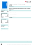
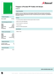
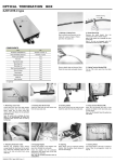
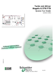
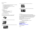
OPTICAL DISTRIBUTION FRAME [Wall Mount Type]
User Manual (Rev.0)
OTB Manual
1. Marking a Cutting Point
2. Sheath Removing
Mark a sheath removing point on the cable
with a piece of tape at a 100cm point from the
cable cut end.
Remove the cable sheath from the marked
point by using a sheath stripper
Remove all plastic tape.
Component List
Unit
Q’ty
Unit Protection Tube
Items
EA
2
Cord Protection Tube
EA
4 X Splice Tray
Cable tie
EA
4
3. Cutting Tension Member
4. Removing Loose Tubes
SET
2
Leave 6cm from the cable and cut off the
tension member.
Wall mounted Dowel
EA
4
Wall mounted Bolt
EA
4
Leave about 4cm from the cable sheath
end and remove the rest of the loose tube.
Clean the cut area by using jelly cleaner.
Note. Be sure not to damage the fiber
optics.
6. Cutting Gasket
7. Inserting Fiber Optic Cable
Cut off the inlet port gasket.
Check the outer diameter of the cable and
cut off the sheath gasket according to the
cable diameter marked on it.
Key
5. Inserting Unit Protection Tube
Insert fibers into the unit protection tubes
carefully all the way up to the point where
loose tubes end.
Wrap the tape around the end point of
protection tube at cable side.
8. Install Ground terminal
9. Fixing Fiber Optic Cable
Secure the cable to the FDF body. If the
cable has metallic sheath and Tension
Member. Insert the Tension Member into the
Ground Terminal for earthing.
Insert the tension member into the T/M fixing
bracket and tighten them together by using a
screwdriver
OTB Manual
10. Routing Protection Tube
Secure the cable to the center of the Susband
Bracket by using a susband
Route protection tubes to the splice tray
inlet and secure the protection tubes on the
splice tray inlet by using cable tie.
OPTICAL DISTRIBUTION FRAME [Wall Mount Type]
User Manual (Rev.0)
11. Pigtail Connection
12. Routing Pigtail
Connect the pigtails to the adapters by turns
on the adapter panel.
Route cord and guide them into stacked
Splice tray. Also insert pigtail into the cord
protection tubes carefully.
Insert cord protection tube into splice tray inlet
and tie together by using cable ties.
14. Recording
15. Cutting Gasket
16. Inserting Patch Cord
17. Distribution Cable Connection
Splice fibers in accordance with
splicing method to be approved
Cut off the outlet port gasket.
Inset patch cord and in the outlet port gasket.
Connect the distribution Cable to the
adapters on the opposite side.
18. Finishing the Termination Box
19. Mounting on the wall
Tie up patch cords with cable tie.
Fasten with a bolt to 4hole by using a drill.
After close cover and fasten it by using
a key to be provided.
13. Splicing
Drill a 4 hole in the wall by using a drill.
Splice fibers in accordance with
splicing method to be approved
After inserting a plastic plug anchor to
4 hole, drive in a plastic plug anchor with
a hammer.
Attach the OTB to the surface of wall.
The OTB has been made under strict quality control and tests. Our products passed several inspection criteria, specifications and other
certification standards.
The technical facts of the products are based upon reliable information, but the user should consider the usage and applicability of the product
before operation. Sellers do not assume any liability resulting from improper use. The contents of this manual are made in lieu of all warranties,
but sellers do not take the responsibility for any damage caused by users or any statements unrelated to this manual.
OTB Manual