1
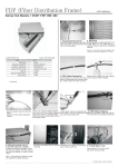
OPTICAL TERMINATION
BOX
SJOF-OTB-C type
Sheath removing
A
1. Marking a Cutting Point
Mark a sheath removing point on the
cable with a piece of tape at 150cm
point from the cable end.
2. Sheath Removing
Remove the cable sheath from the
marked point with a sheath stripper.
Remove plastic tape and dummy fillers.
Clean the loose tube using jelly cleaner.
3. Cutting Tension Member(T/M)
Cut the T/M at 6cm point from the cable
cut end.
6. Inserting Cables
Pull out the cover from the inlet port and
insert the cable from the loose tube end.
7. Fixing Tension Member(T/M)
Place the T/M through the hole of T/M
gripper and tighten it with two bolts using
a screw driver.
Note 1: Be careful not to damage the inner
loose tubes.
Note 2: Do not use damaged cable (“A”
should be free from any flaw. “A”-20cm)
COMPONENTS
Item
Qty
Protection tube(500mm)
Number of cores / 6
Heat shrinkable sleeve(*)
Number of cores
Power pole band(*)
2 ea
Key lock
1 ea
Heat shrink tube
1 ea
Mounting bolt
4 ea
Mounting nut
4 ea
Wall mounting bracket(*)
2 ea
Silver foil tape
1 ea
Sand paper
1 ea
Cleaning tissue
1 ea
Cable tie
4 ea
User manual
1 ea
(*) Optional
4. Removing Loose Tube
Leave about 4cm from the cable sheath
end and remove the rest of the loose
tubes. Clean the cut area using jelly
cleaner and insert fibers into the provided
protection tubes.
5. Inserting Heat Shrink Tube
Insert the cable into the heat shrink tube
from the loose tube end.
Note: The T/M shouldn’t touch the splice tray
after fixing.
Note: Be careful not to damage the inner
fibers. It is recommended to protect the
protection tubes and the cable cut end by
sealing tape.
8. Attaching Protection Tubes
Remove the protection tubes leaving
enough length for attaching it to the splice
tray. Insert the protection tubes into the
inlet on the tray and attach them using
cable ties.
9. Arranging Pigtails
Connect the pigtails to the adapters and
pass them through the cord guide.
Insert the pigtails into the protection
tube(40mm) and attach them in the inlet
of the tray by cable ties.
Note: Use the provided protection tubes by
cutting 40mm.
SAMJIN OTB-C type 040914 rev. 0
10. Splicing
Splice fibers using an approved splicing
method. After the splice, insert sleeves in
each slit accordingly.
11. Storing Fibers
Coil surplus fibers in the tray in a figure 8
shape. After the arrangement, close the
tray lid.
SJOF-OTB-C type
User Manual
70mm
12. Recording
Record each splice on the index card on
the lid.
16. Routing Optical Patch Cord
Connect the patch cords to the opposite
side of adapters. Store the patch cord
slack in the storage spool leaving enough
length for the outside equipment
connection.
13. Rubbing with Sandpaper
Rub the inlet ports and the cable with a
piece of sand paper and clean them with
a cleaner to allow the sealing adhesives
inside of the heat shrink tube to bond to
each side.
14. Wrapping Silver Foil Tape
Wrap the silver foil tape around the cable
70cm from the inlet port to protect cable
sheath from the heat.
17. Locking
Push the door back to the shelf and lock
them with provided keys.
18. Grounding
Connect the external bonding wire to the
ground terminal on the bottom of the shelf
and connect the opposite end of bonding
wire to a designated terminal.
Tip) You can open or close the door easily by
hanging the key to the key home.
SAMJIN OTB-C type 040914 rev. 0 Printed in KOREA, Tel: +81-31-634-6000
[email protected]
All rights reserved by SAMJIN Information & Communications Co., Ltd.
Note: Be careful not to fold or tear the silver
foil tape for tightness.
http://www.samjintel.co.kr
15. Heating Heat Shrink Tube
Push the heat shrink tube up to the cable
inlet port end and heat the heat shrink
tube starting at the inlet port moving away
from it while controlling the fire.

![OPTICAL DISTRIBUTION FRAME [Wall Mount Type]](http://vs1.manualzilla.com/store/data/005974674_1-8c415a2e9ec23148facf1df43798f7a3-150x150.png)