1
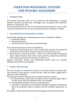
Product Manual MNX10030 / REV A MODEL XE150/250 Series Enclosure for SC200 Series Premium Signal Conditioners Contents Section I Overview Introduction...........................................................................… Description............................................................................... XE150/250 Series Model Selection…………………………….. Specifications……………………………………………………… 2 2 3 4 Section II Installation Mounting………....................................................................... Electrical Connections............................................................. 5 7 Section III Operation Signal Conditioner Configuration………………………………. Operating Procedure................................................................ 9 9 Section IV Maintenance General..................................................................................... Warranty................................................................................... 11 11 Figures Figure 1 (XE150 Series Selection Guide)................................. 3 Figure 2 (XE250 Series Selection Guide)................................. 3 Figure 3 (Mounting Bracket Location)……………………….…. 5 Figure 4 (Cable Entry/Exit)……..……………….……………..… 5 Figure 5 (Conduit Entry)………………….….…...…………...…. 6 Figure 6 (XE150 Series Location of Shield Ground Lug)…….. 6 Figure 7 (XE250 Series Ground Wire Placement)…………….. 7 Figure 8 (XE150T/250T Terminal Block Connections) …….… 8 Figure 9 (XE150/250 Terminal Block Connections)…………… 8 MNX10030 REV A 9/15/2011 Section I Overview Introduction This document contains information on the operation, installation and maintenance of the XE150/250 Series Signal Conditioner Enclosure. This manual is an overview of the system and references the specific component manuals. User manuals are provided with the system for all configurable internal components. Description The XE150/250 Series Signal Conditioner Enclosure is a turnkey solution coming fully populated with signal conditioners, power supply, and terminal blocks for sensor terminations. The signal conditioners are already pre-configured based on the customer’s specific requirements. Terminal blocks are provided for your sensor terminations. These terminal blocks are pre-wired to the signal conditioners and outputs from the signal conditioners are wired to terminal blocks for integration into PLC/DCS systems. Each signal conditioner utilizes screw terminals for the various input/output options such as, ± 20 to 32 VDC power input, ± signal output (outputs include both a 0-10 VDC output and a 4-20mA output and a temperature output in 0-1.2 VDC) and ± sensor input (vibration, displacement and temperature inputs). There is also a green indicator light (Transducer Signal OK) which illuminates when the sensor is properly connected to the transmitter and working correctly. The power supply accepts input voltage of 100-240 VAC, .68A & 50-60 Hz and provides 24 VDC to the signal conditioners and sensors. The power supply terminals include AC Input Terminals (L) & (N), and Ground. DC Output Terminals are utilized in providing power to the vibration transmitters. The output voltage of the power supply is 21.6 – 26.4 VDC. Refer to MNX10020 – PRO Signal Conditioner Transmitter User Manual for specific electrical, performance, and calibration instructions. MNX10030 REV A 9/15/2011 XE150/250 Series Model Selection The XE150/250 Series system has multiple options available to customize to fit your specific requirements. (See Figures 1&2) Figure 1. XE150 Series Selection Guide Figure 2. XE250 Series Selection Guide MNX10030 REV A 9/15/2011 Specifications: Environmental: Operating Temperature Range: 15°F (-10°C) to 140°F (60°C) o Note: If internal temperature of XE150/250 Series Enclosure is to exceed 140F (60C), a method of cooling the enclosure is required or overheating and damage to the system may result. Humidity Range: 0-95% Relative, Non-Condensing Electrical: Power Input Range: 100 VAC to 240 VAC, 0.68 A, 50-60 Hz Physical: Fiberglass Enclosure Dimensions: o 1 to 4 Channel – 12x10x6½ IN (305x254x165 mm) o 5 to 8 Channel – 16x14x8¼ IN (406x356x210 mm) Stainless Steel Enclosure Dimensions: o 1 to 4 Channel – 12x10x7 IN (305x254x178 mm) o 5 to 8 Channel – 16x14x8.5 IN (406x356x216 mm) Ratings: NEMA 4X Refer to MNX10020 – PRO Signal Conditioner Transmitter User Manual for specific electrical, performance, and calibration instructions. MNX10030 REV A 9/15/2011 Section II Installation Mounting 1. Attach the enclosed mounting brackets to the NEMA enclosure at the predetermined locations (if applicable). Mounting Brackets Figure 3. Mounting Bracket Location 2. Cable Entry/Exit: Cables enter and exit through conduit fittings and/or cord grips on the bottom of the enclosure. Input wires are routed through either cord grips (1 per channel) or a 1 ¼” conduit fitting. All output wires are routed through a 1 ¼” conduit fitting. A ½” conduit fitting is provided for an AC power entry. If you are running conduit to your switch box, ensure the conduit cable entry enters from the bottom of the enclosure when mounted. Stainless Steel cord grip option is offered for the XE250 Series for additional protection where plastic cord grips will not suffice. Power Cable Input Cable Outputs Cable Input (From Sensors) Figure 4. Cable Entry/Exit Layout MNX10030 REV A 9/15/2011 NOTE: To ensure moisture will not flow into the Enclosure, a hole should be drilled at the lowest point in the conduit to provide drainage for any moisture. Correct Incorrect Drill Drain Hole Here Figure 5. Conduit Entry 3. Grounding of the Enclosure: Ensure the shield ground wire on the XE150/250 Series Enclosure is connected to earth ground. Note: For XE150 Series Enclosures the customer is required to supply wire from ground to shield ground lug, located on the outside of the enclosure. Note: XE250 Series Enclosures are internally grounded to the enclosure. Shield Ground Lug Figure 6. XE150 Series Location of Shield Ground Lug MNX10030 REV A 9/15/2011 Figure 7. XE250 Series Ground Wire Placement Electrical Connections Inputs Cables enter the enclosure through the designated entry option selected (cord grips or conduit or custom user defined/installed options). All wires are connected to terminal blocks within the enclosure. Standard XE150/250 enclosures uses a 3 position terminal block while XE150T/250T (temperature variant XE150/250) uses a 4 position terminal block. Sensor inputs for both the XE150/250 and XE150T/250T are located on the right side of the enclosure as indicated by the labeling “Sensor Input” XE150/250 Input Wiring: XE150T/250T Input Wiring: Terminal #1 – Signal (+) Terminal #2 – Signal (-) Terminal #3 – Ground Terminal #1 – Signal (+) Terminal #2 – Signal (-) Terminal #3 – Ground Terminal #4 – Temperature Note: If there is no sensor wired to the sensor input terminal, the corresponding transmitter for that channel will not power on. Be sure to power the system on AFTER the sensor has been connected. Note: If utilizing cord grips, ensure that all cord grips are used. Empty cord grips provide a path for contaminates to leak into the enclosure and cause malfunctions. MNX10030 REV A 9/15/2011 Outputs The 4-20mA output of the XE150/250 and XE150T/250T are located on the left side of the enclosure as indicated by the labeling “4-20mA Output”. These terminal blocks follow the same scheme as the inputs – Standard XE150/250 uses a 3 position terminal block and the XE150T/250T uses a 4 position terminal block. XE150/250 Output Wiring: XE150T/250T Output Wiring: Terminal #1 – Signal (+) Terminal #2 – Signal (-) Terminal #3 – Ground Terminal #1 – Signal (+) Terminal #2 – Signal (-) Terminal #3 – Ground Terminal #4 – Temperature Power AC power for the small enclosure and the large enclosures (for both XE150/250 and XE150T/250T) enters the enclosure through a ½” conduit fitting. Customer is required to wire the power directly to the power supply. Note: XE150/250 Series enclosures should be protected from electrostatic discharge voltage. Voltage powering the enclosure should not exceed 240 Volts. Figure 8. XE150T/250T Terminal Block Connections Figure 9. XE150/250 Terminal Block Connections MNX10030 REV A 9/15/2011 Section III Operation Signal Conditioner Configuration Refer to MNX10020 – PRO Signal Conditioner Transmitter User Manual for configuration specifications and procedure for SC200 signal conditioners. Once all wires are connected, apply power to begin operating the Signal Conditioner(s). Make sure the status light is indicating normal mode on each SC200. Operating Procedure To operate the Signal Conditioners inside the enclosure, make sure that all wires are properly connected, and then apply power. CAUTION: Make sure that power input does not exceed specified limits or damage to the system may result. See Table 1. Calibration The Signal Conditioner is calibrated internally during power up. The digital calibration eliminates the need for any adjustments to the Analog Output. Indicators The LED on the front of the Signal Conditioner will indicate the status of the Signal Conditioner. A constant bright LED indicates normal operating condition, and a Flashing LED indicates an error has occurred. STATE 1 – “Normal” Mode Operation LED is a “Solid” ON ( ) STATE 2 – Error Detected LED is flashing ON and OFF in 0.5 second intervals. ( ) Errors can be due to o Input Sensor bias voltage < 5 V. Sensor is considered shorted. o Input Sensor bias voltage > 15 V. Sensor is considered unconnected/missing. o Invalid configuration of switch settings. MNX10030 REV A 9/15/2011 Portable Data Collector Interfacing In order to collect waveform data from the BNC jack on the Signal Conditioner using a portable data collector that supplies constant current power, the data collector must be set so that power to the sensor is turned off. Failure to do so may result in a damaged or non-functional transmitter. MNX10030 REV A 9/15/2011 Section IV Maintenance General There are no customer replaceable parts. It should provide trouble-free continuous service under normal operating conditions. Warranty If any PRO product should ever fail, we will repair or replace it at no charge, as long as the product was not subjected to misuse, natural disasters, improper installation or modification which caused the defect. CONTACT INFORMATION: Connection Technology Center, Inc (CTC) 7939 Rae Blvd. Victor, NY 14564 1-800-999-5290 (US & Canada) 1-585-924-5900 (International) [email protected] – www.ctconline.com MNX10030 REV A 9/15/2011