1
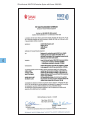
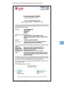
Original instructions
®
AVANTI FALL PROTECTION SYSTEM
User’s, Installation and Maintenance Manual
Runner 2000/2002 & EagleDS Runner
AVANTI Fall Protection System
User‘s Manual and Installation Instructions
All safety statements, specifications, hazards, and inspections defined shall apply only to the version of product specified in this manual. The images and
representations in this manual may vary slightly from the actual product you are using; please review your product label(s) to ensure a proper match.
Date of publication:
10th Edition: September 2014
Revision 3: 15/01/15
Manufacturer:
Avanti Wind Systems A/S
Rønnevangs Allé 6
3400 Hillerød
Denmark
P: (+45) 4824 9024
F: (+45) 4824 9124
E: [email protected]
I: www.avanti-online.com
2
Sales & Service:
Australia
Avanti Wind Systems PTY LTD China
Avanti Wind Systems Denmark
Avanti Wind Systems A/S Germany
Avanti Wind Systems GmbH Spain
Avanti Wind Systems SL UK
Avanti Wind Systems Limited USA
Avanti Wind Systems,Inc India
Avanti Wind Systems,PL Brazil
Avanti Brazil Sistemas Eólicos. S.L. Manufactured Under Process Patent NO.8,499,896.
® Registered in Europe
P: +61 (0) 7 3902 1445
P: +86 21 5785 8811
P: +45 4824 9024
P: +49 (0) 41 21-7 88 85 – 0
P: +34 976 149 524
P: +44 0 1706 356 442
P: +1 (262) 641-9101
M: +91 95 00 173 492
P: +55 85 9671 6336
Index
1.Limited Warranty . . . . . . . . . . . . . . . . . . . . . . . . . . . . . . . . . . . . . 6
2.Cautions . . . . . . . . . . . . . . . . . . . . . . . . . . . . . . . . . . . . . . . . . . . . 7
3.Description of equipment . . . . . . . . . . . . . . . . . . . . . . . . . . . . . . 8
3.1 Purpose . . . . . . . . . . . . . . . . . . . . . . . . . . . . . . . . . . . . . . . . . 8
3.2 Function . . . . . . . . . . . . . . . . . . . . . . . . . . . . . . . . . . . . . . . . . 8
3.3 Component overview . . . . . . . . . . . . . . . . . . . . . . . . . . . . . . 8
3.4 Marking . . . . . . . . . . . . . . . . . . . . . . . . . . . . . . . . . . . . . . . . . 9
4.Installation . . . . . . . . . . . . . . . . . . . . . . . . . . . . . . . . . . . . . . . . . . 9
4.1 Installation requirements . . . . . . . . . . . . . . . . . . . . . . . . . . . . 9
4.2 Installation of the rail system on the ladder . . . . . . . . . . . . . 10
4.2.1 Safety rail at the tower flange connections . . . . . . . . . 11
5.Inspection before the first use . . . . . . . . . . . . . . . . . . . . . . . . . . . 12
6.Daily inspection . . . . . . . . . . . . . . . . . . . . . . . . . . . . . . . . . . . . . . 12
7.Instructions for use . . . . . . . . . . . . . . . . . . . . . . . . . . . . . . . . . . . 12
7.1 Instructions for use of Runner 2000/2002 . . . . . . . . . . . . . . . 12
7.1.1 Attaching the Runner 2000/2002 to the safety rail . . . . 12
7.1.2 Releasing the Runner 2000/2002 from the safety rail . 13
7.2 Instructions for use of EagleDS Runner . . . . . . . . . . . . . . . . . 13
7.2.1 Attaching the EagleDS Runner to the safety rail . . . . . . . 13
7.2.2 Releasing the EagleDS Runner from the safety rail . . . . 14
8.Maintenance . . . . . . . . . . . . . . . . . . . . . . . . . . . . . . . . . . . . . . . . 15
8.1 Cautions . . . . . . . . . . . . . . . . . . . . . . . . . . . . . . . . . . . . . . . . . 15
8.2 Storage . . . . . . . . . . . . . . . . . . . . . . . . . . . . . . . . . . . . . . . . . 15
8.3 Annual inspection . . . . . . . . . . . . . . . . . . . . . . . . . . . . . . . . . 15
8.4 Inspection procedure . . . . . . . . . . . . . . . . . . . . . . . . . . . . . . 15
8.4.1 Ladder rungs . . . . . . . . . . . . . . . . . . . . . . . . . . . . . . . . . 15
8.4.2 Ladder stiles . . . . . . . . . . . . . . . . . . . . . . . . . . . . . . . . . 16
8.4.3 Flange connection kits . . . . . . . . . . . . . . . . . . . . . . . . . 16
8.4.4 Ladder ends . . . . . . . . . . . . . . . . . . . . . . . . . . . . . . . . . . 16
8.4.5 Safety rail . . . . . . . . . . . . . . . . . . . . . . . . . . . . . . . . . . . . 16
8.4.6 Fish-joints . . . . . . . . . . . . . . . . . . . . . . . . . . . . . . . . . . . 16
8.5 Ordering spare parts . . . . . . . . . . . . . . . . . . . . . . . . . . . . . . . 16
9. Appendix A: Annual inspection checklist . . . . . . . . . . . . . . . . 17
10. Appendix B: Daily inspection checklist of Runner 2000/2002 19
11. Appendix C: Daily inspection checklist of EagleDS Runner . . 20
12. Appendix D: Inspection log sheet . . . . . . . . . . . . . . . . . . . . . . 21
3
CE certificate of AVANTI Fall Protection System with Runner 2000/2002:
4
CE certificate of AVANTI Fall Protection System with EagleDS Runner:
5
Limited Warranty
Avanti Wind Systems A/S warrants that commencing from the date of
INCLUDING, BUT NOT LIMITED TO, ANY IMPLIED WARRANTY OR CON-
shipment to the Customer, and continuing for a period of the longer
DITION OF MERCHANTABILITY, FITNESS FOR A PARTICULAR PURPOSE,
of 365 days thereafter, or the period set forth in the standard Avanti
NON-INFRINGEMENT, SATISFACTORY QUALITY, COURSE OF DEALING,
warranty, the Fall Protection System (“Product”) described in this
LAW, USAGE OR TRADE PRACTICE ARE HERBY EXCLUDED TO THE MAX-
Manual will be free from defects in material and workmanship under
IMUM EXTENT PERMITTED BY APPLICABLE LAW AND ARE EXPRESSLY
normal use and service when installed and operated in accordance
DISCLAIMED BY AVANTI. IF, PURSUANT TO ANY APPLICABLE LAW, TO
with the provisions of this Manual.
THE EXTENT AN IMPLIED WARRANTY CANNOT BE EXCLUDED AS PROVIDED IN THIS LIMITED WARRANTY, ANY IMPLIED WARRANTY IS LIM-
6
This warranty is made only to the original user of the Product. The
ITED IN TIME TO THE SAME DURATION AS THE EXPRESS WARRANTY
sole and exclusive remedy and the entire liability of Avanti under
PERIOD SET FORTH ABOVE. BECAUSE SOME STATES DO NOT PERMIT
this limited warranty, shall be, at the option of Avanti, a replacement
LIMITATIONS ON THE DURATION OF IMPLIED WARRANTIES, THIS MAY
of the Product (including incidental and freight charges paid by the
NOT APPLY TO A GIVEN CUSTOMER. THIS LIMITED WARRANTY GIVES
Customer) with a similar new or reconditioned Product of equivalent
CUSTOMER SPECIFIC LEGAL RIGHTS, AND CUSTOMER MAY HAVE
value, or a refund of the purchase price if the Product is returned to
OTHER LEGAL RIGHTS UNDER APPLICABLE LAWS. This disclaimer shall
Avanti, freight and insurance prepaid. The obligations of Avanti are
apply even if the express warranty fails of its essential purpose.
expressly conditioned upon return of the Product in strict accordance
with the return procedures of Avanti.
In any cases of dispute the English original shall be taken as
authoritative.
This warranty does not apply if the Product (i) has been altered without the authorization of Avanti or its authorized representative; (ii)
has not been installed, operated, repaired, or maintained in accordance with this Manual or other instructions from Avanti; (iii) has been
subjected to abuse, neglect, casualty, or negligence; (iv) has been
furnished by Avanti to Customer without charge; or (v) has been sold
on an “AS-IS” basis.
Except as specifically set forth in this Limited Warranty, ALL EXPRESS
OR IMPLIED CONDITIONS, REPRESENTATIONS AND WARRANTIES,
1 Caution
a) The AVANTI Fall Protection System (hereafter named as FPS) shall
only be operated by users trained in daily inspection, use and work at
heights.
b) A user is trained on the correct usage of the AVANTI Fall Protection
System (FPS) and is familiar with the following standards: EN 353-1, EN
363 and EN 365.
c) A competent has successfully participated in the AVANTI Fall Protection
course.
d) A competent is qualified personnel authorised by AVANTI to perform
installation, inspection and maintenance tasks.
e) The installation, maintenance and testing of the FPS may only be performed by a competent person.
f) Users are obliged to read and understand this User’s Manual.
g) A copy of the User’s Manual shall be handed out to the FPS users and
shall be available for reference.
h) If more than one person is trusted with one of the above tasks, the
employer shall appoint a supervisor in charge of operation.
i) If the FPS is re-sold outside the original country of destination, the
reseller shall provide instructions for use, for maintenance, for periodic
examination and for repair in the language of the country in which the
product is to be used.
j) The ladder system shall be capable of supporting 15 kN. This shall be
k)
l)
m)
n)
o)
p)
q)
verified by calculations made by a qualified engineer or by static load
testing.
The FPS shall not be used by persons under the influence of alcohol or
drugs that may jeopardise the safety.
The FPS shall not be used by persons affected by vertigo, heart or lung
disorders, or other known weakening diseases/conditions.
The FPS users shall be aware of the dangers of suspension trauma
should a fall occur.
The owner shall ensure that a rescue plan is in place and that the users
are familiar with it. The rescue plan shall deal with any emergencies that
could arise during ascent and descent with the FPS.
No warranty is provided against damage resulting from reconstruction
or modification of equipment or use of non-original parts which are not
approved by the manufacturer.
The runner shall be handed out and treated as a personal protection
equipment.
The weight of the user including clothing and equipment shall be between 40 and 136 kg.
r) The maximum number of multiple users is 3.
s) In the first two meters above the ground level, the user may not be
protected against hitting the ground if a fall occurs.. Other additional
safeties shall be provided for this purpose.
t) Prior to the first use of the FPS, a competent must inspect and approve the complete FPS.
u) If oil, grease or the like has leaked onto the safety rail – wipe it off.
v) If oil, grease, chemicals or the like has leaked onto the shock absorber
or in any kind been in contact with the webbing, have an AVANTI FPS
technician replace the shock absorber.
w) The shock absorber has a limited life. Its date of expiration is printed
on the shock absorber label.
x) The operation temperature of the FPS is -30º / +60º Celsius.
y) The FPS shall only be used in connection with a full body harness that
is approved according to EN 361.
z) The FPS has been tested and approved according to EN 353-1 and
RfU 11.073.
aa) The type-examination of the FPS has been performed by: FORCE
Certification A/S, EC Notified Body 0200, Park Allé 345, DK-2605
Brøndby.
ab) The production control of the FPS is performed by the same notified
body.
ac) These instructions shall be kept together with the permanent installed
parts of the FPS (i.e. the rail system).
The owner shall verify the need for FPS inspections with the local authority and comply with the standards specified.
ad) When working at heights, the user shall minimise both the risk of
potential falls and the potential fall distance.
ae) In order to avoid collisions with the ground or obstacles should a fall
occur, the user shall verify the free space required beneath his/her
actual position taking into account sharp edges, electrical conductivity
and pendulum falls.
af) The safety of the users depends upon the continued efficiency and
durability of the FPS. Thus, regular periodic inspections shall be carried out, minimum every 12 months.
ag) All the FPS parts have been especially developed and tested for
AVANTI´s FPS. Thus, they shall not be used as part of other Fall Protection Systems.
7
ah) The combination of FPS parts in anyway other than the intended
will jeopardize safety. Thus, the FPS parts shall not be combined in
anyway other than the intended.
3.3Component overview
a) The FPS comprises the rail system and the runner system.
ai) The FPS shall never be adapted, extended, or changed in any way.
Rail
Rung fitting
Runner
Shock
Absorber
Carabiner
8
3 Description of equipment
3.1 Purpose
a) The FPS is intended for use during ascent and descent on stationary
ladders installed in towers, pylons, well shafts, or alike.
The FPS is a safety system that arrests a fall of the user during climbing.
The runner travels along a safety rail.
The safety rail is designed for permanent installation at one place.
The safety rail can be installed on ladders of different shapes and brands
as long as an approval is issued before by AVANTI.
f) The FPS is not designed for securing horizontally or for securing
equipment.
g) The FPS may not be used outside its limitations, or for any purpose other
than that for which it is intended.
b) The safety rail system comprises: the safety rail sections, the rung fittings, the top and bottom rail-stops, the fish-joints, hammerhead screws and self-locking nuts.
c) The runner comprises: the runner itself, the shock absorber, and the carabiner.
d) There are two runner models covered in this manual: Runner 2000/2002 and EagleDS Runner. Both models fit the AVANTI rail.
b)
c)
d)
e)
3.2 Function
a) The user attaches the runner to the designated D-ring of his full body harness by means of the integrated shock absorber and the carabiner.
b) Before starting to climb, the user clicks the runner on the safety rail and
checks its locking.
c) When climbing, the runner glides along the safety rail. In case that the
user experiences a fall, the runner will lock on the safety rail and arrest
Runner 2000/2002
EagleDS Runner
the person falling.
User’s Manual and Installation Instructions - AVANTI Fall Protection
3.4Marking
4 Installation
Upward direction when mounted onto rail
Read instructions before use
Runner production no.
EEC-notified body no.
4.1Installation requirements
STOP
AVANTI product name (Runner System 2000/2002 or EagleDS)
Standard no.
A competent shall be in charge of the FPS installation. The competent shall take full responsibility for the installation and shall
guarantee that it is done in accordance to these instructions.
Runner System 2000/2002
User weight / Poids utilisateur
40 - 136 kg
EN353-1: 2002 ANSIZ359.1-2007 CSA Z259.2.1.98
Class: AS Type: Rail Mount Size: AVANTI Fall Protection Rail Only. Read
and follow all instructions before use; Inspect device prior to each use.
0200
Classe: AS Type: Support de rail Taille: Uniquement pour rail de protection
contre les chutes AVANTI. Veuillez lire et suivre toutes les instructions avanti
l'utilisation et inspecter le dispositif avant chaque utilisation.
www.avanti-online.com
P/Tel.: (+45) 4824 9024
Serial No./N° de serie:
Production date/Date de Production:
Runner rating plate
EEC-notified body no.
Standard no.
Production batch no.
Read instructions before use
System 2000/2002
0200
EN353-1: 2002
ANSI Z359.1-2007
CSA Z259.2.1.98
Read supplied instructions prior to use. Min.distance 6 m (19.7 feet) between users.
Maximum number of users: 3. Systems must be inspected by a certified AVANTI technician
annually under normal use or inmediately in the event of a shock load as a result of a fall.
Only AVANTI replacement parts may be used with the system.
www.avanti-online.com
P: (+45) 4824 9024
Serial No.
Production date:
WARNING
Using replacement parts,
components not approved
by AVANTI or modified
runners with the rail
system could result in
serious injuries or death.
a) The FPS shall only be installed with original system parts.
b) All FPS elements shall be checked on site, even if the ladders are supplied with the rails already fitted.
c) The vibrations and torsional stress are absorbed by the ladder joints, not
by the safety rail.
d) Ensure that the ladder intended for mounting the FPS complies with the
requirements of EN 131 and EN ISO 14122. The internal rung width shall
be minimum 340mm (all AVANTI ladders meet this requirement).
e) The ladders with rung geometries different to AVANTI‘s may call for
special rung fittings. Prior to installation, these ladders shall be calculated,
tested and approved by AVANTI.
f) Before installing the rail system, ensure that all parts are present. Refer to
the parts list supplied with the FPS.
g) The ladders shall be installed vertically with a maximum inclination of ±5º.
h) The parts of the safety rail system to be installed are shown below.
FOLLOW ALL
INSTRUCTIONS
Safety rail rating plate
Max distance between safety rail and harnes 0,3 m
Shock absorber expiration date
Batch no.
Standard EN no. for shock absorber
EEC-notified body no.
Shock absorber label
Safety rail section (backside)
Rung fitting
9
Hammerhead bolt with self-locking nut
A rung fitting mounted on the rail
a. For each rail section, mount a rung fitting on the first (lowest) rung of the
ladder. b. For each rail section, mount a rung fitting on the last (highest) rung of
the ladder. This is also necessary even if the second or third last rung of the
ladder are mounted with a rung fitting.
c. For each rail section, mount a rung fitting at least every third rung,
never leaving more than 2 consecutive rungs without a rung fitting.
e) Use a fish-joint to join 2 consecutive safety rail sections.
f) Use 4 screws to mount each fish-joint.
g) Leave a gap between 2 consecutive safety rail sections of at least 1 mm
and maximum 4 mm.
Fish joint connector
Sample of rail-stop to be used at top and bottom of the rail installation
10
Flange connection kit
1 mm ≤ x ≤ 4 mm
Bottom rung of a
ladder section
Top rung of a
ladder section
4.2Installation of the rail system on the ladder
a) Place the safety rail on the centre and front side (the climber´s side)
of the ladder.
b) Place the safety rail so that the guide seat is situated on the left side.
h) Place the hammerhead screws with the indicator marks in an angle of 70°.
i) Tighten all the self-locking nuts to 8 N•m and ensure that they sit with the 70º
angle.
Indicator mark
70°
Guide seat
The guide seat is situated on the left side
c) Fix the safety rail to the ladder by means of the rung fittings.
d) Mount the rung fittings using hammerhead screws and self-locking
nuts, and following the instructions below.
70°
Angle of the indicator marks and of the self-locking nuts
User’s Manual and Installation Instructions - AVANTI Fall Protection
j) Use the supplied self-locking nuts at all times.
k) Ensure that each screw extends from the nut by at least half of the
thread diameter.
STOP
A rail-stop shall be installed at the top and bottom of the rail, and at any
provisional point where the runner can unintentionally run off the rail.
l)
Mount the top and bottom rail-stops on the safety rail, at the highest
and lowest travel points respectively.
m) The distance between the top end of the safety rail and the top rung
of the complete tower shall be equal or greater than 100 mm. The
distance between the bottom end of the safety rail and the floor level
shall be equal or less than 600 mm.
Top rung
of the
complete
tower
Minimum
100 mm
Bottom rung of
a tower section
Tower flange
Top rung of a
tower section
55mm ≤ x ≤ 100mm
Maximum 600 mm
Top
rail-stop
55mm ≤ x ≤ 100mm
Bottom
rail stop
Bottom rung of the
complete tower
Floor
Length limits of the top and bottom ends of the safety rail
m) During the erection phase of the wind turbine tower sections (i.e. when
the tower sections are being connected vertically), a top rail-stop shall
be mounted on the safety rail at the highest point of each tower section. This way, the technicians will be able to use the FPS during this
phase.
n) If the safety rail and the ladder are installed in a wind turbine tower
section before the tower is erected, their final position shall be adjusted
during the tower erection.
4.2.1
Safety rail at the tower flange connections
a) A rung fitting shall be mounted on the penultimate top and penultimate
bottom ladder-rung of each tower section (i.e. at tower flange connection).
b) The top end of the safety rail of each tower section shall end minimum
55 mm and maximum 100 mm above the second top rung fitting.
c) The bottom end of the safety rail of each tower section shall end
minimum 55 mm and maximum 100 mm below the rung fitting.
d) The safety rails of two consecutive tower sections shall be connected by means of a flange connection kit.
e) The distance between the safety rails of two consecutive tower
sections shall be equal or less than the length of the flange connection kit.
11
STOP
Do not use the FPS if it looks defective or if parts are missing.
If the FPS has blocked a fall or has been put out of service
because of doubts, it may only be put back to service after an
inspection by a competent is performed. The competent shall
confirm in writing that the FPS is found in safe condition to be
used again.
7 Instructions for use
Flange connection kit
The detailed installation procedure of the flange connection
kit is available upon request to AVANTI.
7.1Instructions for use of Runner 2000/2002
7.1.1 Attaching the Runner 2000/2002 to the safety rail
STOP
5 Inspection before the first use
12
STOP
Before the first use, a competent shall inspect the FPS.
The inspection before the first use shall be carried out following the
inspection procedure. During the inspection, the “Appendix A: Annual
Inspection Checklist” and the “Appendix D: Inspection log sheet” shall
be filled in for future reference.
6 Daily inspection
a) Before using the runner, perform a daily inspection following the “Appendix B:
Daily Inspection Checklist for Runner 2000/2002” or the “Appendix C: Daily
Inspection Checklist for EagleDS Runner”. If any of the checks does not pass, the
runner system cannot be used.
b) During the ascent, look for visible damages or loose parts such as loose screws
on ladder, rail or joints.
c) Equipment with defects or equipment that leaves doubt concerning safe use
must be checked by a competent person.
Before using the runner, make sure that you are wearing an ap
proved full body harness. Before attaching the runner to the rail,
ensure that you are in a safe area (ground level) or attached to an alternative fall protection.
Before attaching the runner to the rail, ensure that it is attached to the
D-ring of the full body harness in order to avoid dropping it.
The carabiner shall only be connected to the D-ring of the full body
harness located on the front side of the user and located at the chest
height.
The D-ring shall comply with the demands for climbing in vertical fall
arrest safety systems on ladders (see the user´s manual of the full
body harness).
When attaching the carabiner, ensure that the shock absorber is
not twisted between the runner and the carabiner. A twisted shock
absorber may cause the FPS to fail.
a) Place the runner on the
safety rail ensuring that the
arrow on the plate of the
runner points upwards.
Otherwise, the runner will
not arrest a fall.
User’s Manual and Installation Instructions - AVANTI Fall Protection
b) Open the runner by pressing the left bottom pin and pulling apart both
body sides of the runner simultaneously.
c) While lifting the lever, tilt the runner so the runner is parallel and close to
7.1.2 Releasing the Runner 2000/2002 from the safety rail
a) Before stepping in or stepping off the ladder, attach alternative fall protection.
the safety rail.
STOP
d) Push together the two body parts of the runner until the left bottom pin
pops out. You will hear a click sound.
Before releasing the runner from the rail, ensure that you are
in a safe area (ground level) or attached to an alternative fall
protection.
Before releasing the runner from the rail, ensure that the runner is without load and that there is no risk of falling.
Before releasing the runner from the rail, ensure that it is
attached to the D-ring of the body harness in order to avoid
dropping it.
b) Release the runner from the rail by pressing the left bottom pin and
pulling the runner body parts apart simultaneously.
c) Remove the runner from the rail. It is not intended to be parked on the
rail. The runner is personal and shall be in reach in case of an emergency.
STOP
If any damages or faults are found during operation, or any
other circumstance which may jeopardise safety: immediately
stop the work in progress, and contact the site responsible,
e.g. the turbine owner or the site foreman.
7.2Instructions for use of Eagle
DS
Runner
e) Make sure the runner is locked correctly by pulling the lever
downwards and confirming that the runner locks on the rail.
f) Climb the ladder keeping a distance of minimum 10 cm between torso
and ladder. This distance guarantees an optimal operation, enhanced
safety and better climbing ergonomics.
g) During ascent or descent, keep a minimum distance of 6 meters
between each user.
STOP
Each rail section shall only be used by one user at a time, since
having more users using the same rail section simultaneously
would jeopardise its structural resistance.
Engaging the release mechanism of the runner during ascent or descent can jeopardise the function of the braking mechanism.
The FPS is only approved as a fall arrest safety when ascending or
descending the ladder. Thus, the fall arrest system shall never be used
for work positioning. If work positioning at the ladder is required, use
separate dedicated and approved work positioning equipment.
STOP
The cautions listed previously for Runner 2000/2002 are
equally applicable to EagleDS Runner. Follow them closely.
7.2.1 Attaching the EagleDS Runner to the safety rail
a) Pull out the plunger and rotate the locking lever downwards (see
images below).
13
b) Open the runner by pressing
the right button and pulling apart
both body sides of the runner
simultaneously.
c) Place the runner on the safety rail ensuring that the arrow on the plate of the runner points upwards.
e) Push together the two body
parts of the runner until the
push button pops out and you
hear a click.
f) Pull out the plunger and rotate the locking lever upwards (see images
below).
Arrow
14
g) Make sure that the runner is locked correctly by pulling the lever downwards and confirming that the runner locks on the rail.
d) While lifting the lever, tilt the runner so the runner is parallel and close to
the safety rail.
h) Climb the ladder keeping a distance of minimum 10 cm between torso and ladder. This distance guarantees an optimal operation, enhanced safety and better climbing ergonomics.
i)
During ascent or descent, keep a minimum distance of 6 meters between each user.
User’s Manual and Installation Instructions - AVANTI Fall Protection
7.2.2 Releasing the EagleDS Runner from the safety rail
8Maintenance
a) Pull out the plunger and rotate the lever downwards to the horizontal position (see images below).
8.1Cautions
a) Keep all the parts free of oil, grease, paint, aggressive chemicals
and alike.
b) Clean the shock absorber using a weak sulpho-solution and a soft
brush. Subsequently, flush it with plenty of pure water.
c) Never place liquids or sharp objects in the vicinity of the FPS as
these might damage it.
d) If the FPS gets wet, dry the runner and the safety rail with a dry
cloth. Let the shock absorber air-dry naturally. Do not use any kind of
heating.
b) Press and hold the push button.
8.2Storage
a) Store the runner system out of direct sunlight and protected from
heat and dust.
8.3Annual inspection
a) At least every 12 months, a competent person shall inspect the
FPS (both runner and rail). Otherwise, the warranty will be void and
AVANTI will renounce all liability and claims that may appear.
STOP
c) Open the runner by pressing the push button and by pulling apart both body sides of the runner simultaneously (see image below).
STOP
The annual inspection may only be conducted by a competent.
The annual inspection shall be carried out following the inspection procedure. During the inspection, the “Appendix A: Annual
Inspection Checklist” and the “Appendix D: Inspection log sheet”
shall be filled in for future reference.
b) During this inspection, special attention shall be paid to the safety
rail and the runner
d) Remove the runner from the safety rail.
8.4Inspection procedure
8.4.1 Ladder rungs
a) Ensure that no dents, holes, or cracks have any influence on the
rung stability.
b) The dents shall not exceed 10 mm in diameter or be more than 1
mm deep.
c) If dents are found on the rung edges or corners, the step stability
can no longer be guaranteed. In such case, replace the ladder section.
15
19
|
9|
|7|8|
4|
NEXT
INSPECTION
5|6
|
16
8.4.5 Safety rail
a) Ensure that the safety rail sections are mounted according to the
installation instructions of this manual.
b) Ensure that no sharp rail ends are present.
c) Check the legibility of the product marking. If marking is not present, a
competent shall replace them.
d) During the erection of the wind turbine towers, top and bottom railstops shall be mounted on each individual tower section.
e) Ensure that top and bottom rail-stops are mounted.
11 | 12 | 14
8.4.4 Ladder ends
a) On the top and bottom ends of the complete ladder system, a
protection guard (such as the AVANTI rubber feet or end cap) shall be put
in place on the stiles.
16 | 17 | 18 |
8.4.3 Flange connection kits
a) The distance between the rungs at tower flange connection shall be
minimum 255 mm and maximum 300 mm.
15
|
deep.
c) If dents are found on the stile edges or corners, the stile stability can no
longer be guaranteed. In such case, replace the ladder section.
8.4.7 Circular inspection sticker
a) Ensure that the sticker is present and that the due date has not
expired.
10
|
8.4.2 Ladder stiles
a) Ensure that no dents, holes, or cracks have any influence on the stiles´
stability.
b) The dents shall not exceed 20mm in diameter or be more than 1 mm
20 | 1 | 2 | 3
|
8.5Ordering spare parts
a) If any part of the FPS is found to be broken, unsafe or missing,
put the FPS out of service immediately.
b) Subsequently, contact an AVANTI representative to replace/
repair the missing parts.
c) Finally, a competent person shall carry out an inspection
following the inspection procedure.
8.4.6 Fish-joints
a) Ensure that the fish-joints are mounted with 4 hammerhead screws.
b) Ensure that the gap between consecutive safety rails is minimum 1mm
and maximum 4 mm.
c) Ensure that the indicator mark of each hammer¬head screw and the
self-locking nuts are at an angle of 70º.
d) Make sure that all hammerhead screws and self-locking nuts of the rail
system are present and torqued to 8 N·m.
User’s Manual and Installation Instructions - AVANTI Fall Protection
Appendix A: Annual inspection checklist
Type of AVANTI Runner:
Runner 2000/2002 or Eagle DS
User´s name:
Standards:
EN353-1 / RfU11.073 / AS/NZS1891.3
Phone:
Tower (WEA-No.):
Name of inspector:
Date of inspection:
Date of next inspection:
1
Ladder system
1.1
Rungs
OK
NOK
COMMENTS
OK
NOK
COMMENTS
OK
NOK
COMMENTS
OK
NOK
COMMENTS
OK
NOK
COMMENTS
Are dents less than 10 mm in diameter or 1 mm deep?
Are the rung ends fixed tight to the stiles?
Are the rungs free of cracks?
1.2
Stiles
Are dents less than 20 mm in diameter or 1 mm deep?
Are the stile ends free of dents?
Are the stiles free of cracks?
1.3
Flange connection kits
Is the distance between the rungs of consecutive ladder sections at tower flange between 255 and 300 mm?
1.4
Ladder ends
Are the AVANTI rubber feet or end caps mounted?
1.5
General
Is the ladder system free of dirt (oil, corrosion, paint, etc.)?
2
Safety rail system
2.1
Safety rail sections
Are the safety rail sections mounted on the front side?
Is the guide seat of each safety rail section placed on the left side?
Are the ends of each safety rail section free of sharp edges?
2.2
Rung fitting
Is there a rung fitting on the first (lowest) rung of each ladder section?
Is there a rung fitting on the last (highest) rung of each ladder section?
Is there a rung fitting on at least every third rung of each ladder section?
Is each rung fitting free of damages?
2.3
Fish-joints
Is each fish-joint mounted with 4 hammerhead screws?
Are all the indicator marks of the hammerhead screws and the self-locking nuts at an angle of 70º?
2.4
General
Is the safety rail system free of dirt (oil, corrosion, paint, etc.)?
3
Others
3.1
Resting platforms
Are the resting platforms in place and fixed at every 15 m?
3.2
Screws
Are all the screws in place and torqued properly?
3.3
Labels and markings
Are all the labels and markings legible?
4
Runner system
4.1
-
5
Final assessment
5.1
-
Is the safety rail system free of damages?
Is the runner approved for use?
Is the FPS approved for use?
This inspection shall be carried out before the first use and at least every 12 months by AVANTI or by a competent. This checklist and the Inspection log sheet shall be filled in and filed for future reference.
Inspector´s Signature:
Appendix B: Daily inspection checklist of Runner 2000/2002
ISSUE DESCRIPTION
1
PASS
FAIL
ISSUE DESCRIPTION
9
Is the runner´s body free of corrosion, deformation and other damages? (See Fig. 1)
Is the carabiner free of marks, deformities, wear and traces of
corrosion? (See Fig. 8)
COMMENTS
COMMENTS
2
10
Is the brake lever free of corrosion, deformation and other damages? (See Fig. 2)
Is the return spring and articulation of the carabiner opening, closing
and locking properly? (See Fig. 9)
COMMENTS
COMMENTS
3
11
Is the middle plate tightly attached by the 4 fixed rivets? (See Fig. 3)
COMMENTS
4
12
Is the aluminium serial plate tightly attached by the 2 fixed rivets?
(See Fig. 4)
13
14
Is the spring securely attached? Is it retracting the lever automatically? (See Fig. 12)
COMMENTS
Is the blank aluminium plate present and sitting tight? (See Fig. 6)
15
COMMENTS
8
Does the brake lever move up and down smoothly? (See Fig. 12)
COMMENTS
Are the synthetic guides tightly seated and without bruises and
marks? (See Fig. 5)
COMMENTS
7
Does the runner close and open easily without friction or resistance? (See Fig. 11)
COMMENTS
COMMENTS
6
Does the black strap of the shock absorber cover the carabiner end
completely? (See Fig. 10)
COMMENTS
Is the middle plate free of deformation? (See Fig. 3)
COMMENTS
5
PASS
Is the shackle securely attached and free from marks, deformities,
wear and traces of corrosion? (See Fig. 13)
COMMENTS
Does the shock absorber show a normal shape? Are the absorber
and the cover free of cuts, burns, seams and visible signs of wear?
(See Fig. 7)
16
Does the runner slide smoothly along the rail? (See Fig. 13)
COMMENTS
COMMENTS
17
Is the circular inspection sticker present? Has the due date for
annual inspection not expired? (See Fig. 12)
COMMENTS
VISUAL TEST
1
8
2
3
9
4
10
5
11
6
12
7
13
FAIL
Appendix C: Daily inspection checklist of EagleDS Runner
ISSUE DESCRIPTION
1
PASS
FAIL
ISSUE DESCRIPTION
9
Are the runner´s bodies free of corrosion, deformation adn cracks?
(See Fig. 1)
Is the carabiner free of marks, deformities, wear and traces of
corrosion? (See Fig. 8)
COMMENTS
COMMENTS
2
10
Is the brake lever free of corrosion, deformation and other damages? (See Fig. 2)
Is the return spring and articulation of the carabiner opening, closing
and locking properly? (See Fig. 9)
COMMENTS
COMMENTS
3
11
Does the locking lever lock and unlock correctly? (See Fig. 3)
COMMENTS
4
12
Is the aluminium serial plate tightly attached by 2 fixed rivets? (See
Fig. 5)
13
Are the 6 rollers tightly placed and free of bruises and marks? (See
Fig. 6)
14
Does the runner slide smoothly along the rail? (See Fig. 13)
COMMENTS
Is the circular inspection sticker present? Has the due date for
annual inspection not expired? (See Fig. 4)
15
COMMENTS
8
Is the shackle tightly attached and free of marks, deformities, wear
and traces of corrosion? (See Fig. 12)
COMMENTS
COMMENTS
7
Does the runner close and open easily without friction or resistance? (See Fig. 11)
COMMENTS
COMMENTS
6
Does the black strap of the shock absorber cover the carabiner end
completely? (See Fig. 10)
COMMENTS
Does the push button move up and down correctly? (See Fig. 4)
COMMENTS
5
PASS
Does the shock absorber show a normal shape? Are the absorber
and the cover free of cuts, burns, seams and visible signs of wear?
(See Fig. 7)
Do the torsion springs work properly (i.e. the lever can be moved
up and down smoothly)? (See Fig. 12) Are they securely attached?
(See Fig. 14)
COMMENTS
COMMENTS
VISUAL TEST
1
2
3
4
5
6
7
8
9
10
11
12
13
14
FAIL
Appendix D: Inspection log sheet
Runner model:
(Runner 2000/2002 or
EagleDS runner)
Installation address:
Avanti Wind Systems A/S ·
DK-3400 Hillerød
Tel:+45 48 24 90 24 · Fax: +45 48 24 91 24
www.avanti-online.com
Date of purchase:
Serial number of runner:
Date first put into service:
Periodic examination and repair history
Date
Identification no.:
Reason for entry
(per. examination)
OK / not OK
Inspector
Due date of next annual inspection
Australia
Avanti Wind Systems PTY LTD
203 Blackburn Rd,
MT Waverley, VIC 3149
P: +61 (0) 7 3902 1445 · F: +61 (0)7 3902 1252
China
Avanti Wind Systems
Building 4 · No, 518
Gangde Road · XiaokunshanTown
Songjiang District · 201614 Shanghai
P: +86 21 5785 8811 · F: +86 21 5785 8815
Denmark
Avanti Wind Systems A/S
Rønnevangs Allé 6 · 3400 Hillerød · Denmark
P: +45 4824 9024 · F: +45 4824 9124
Germany
Avanti Wind Systems GmbH
Max-Planck-Str. 10 25335 Elmshorn
P: +49 (0) 41 21-7 88 85 – 0 · F: +49 (0) 41 21- 7 88 85-20
Spain
Avanti Wind Systems SL · Poligono Industrial Centrovia
Calle Los Angeles No 88 nave 1 · 50198 La Muela
P: +34 976 149524 · F: +34 976 149508
UK
Avanti Wind Systems Limited
Caldershaw Business Centre · Unit 29
Ings Lane · Rochdale · OL12 7LQ
P: +44 0 1706 356 442
India
Avanti Wind Systems India Private Ltd
Old No. 28 · New No. 41
Vellala Street · Aiyanambakkam
Chennai 600095 · Tamil Nadu
P: +91 44 6455 5911
Revision 3: 15/01/15
47840008 - FPS manual EN
10th Edition: September 2014
USA
Avanti Wind Systems, Inc.
5150 S. Towne Drive · New Berlin · Wisconsin 53151
P: +1 (262) 641-9101 · F: +1 (262) 641-9161
Brazil
Avanti Brazil Sistemas Eólicos. S.L.
Rodovia BR-116, Km21.
Fortaleza. Ceará
Brazil 61760-000
P: +55 85 9671 6336
I: www.avanti-online.com · E: [email protected]