1
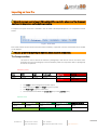
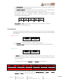
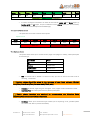
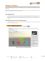
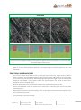
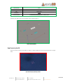
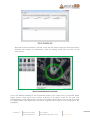
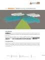
About this tutorial Smart3DCapture allows you to import all needed information to create a block from an XML or an Excel file (.xls). This is useful in many situations, including the case of aerial projects containing a large amount of photos, when orientation and positioning values are known a priori, either coarse values or accurate values estimated by third party software. While the concepts are generally known, it appears that many of them are ambiguous and depend on conventions. This tutorial will guide you in this convention jungle. It will teach you how to import data from Excel and XML files, how to check the consistency and the accuracy of the imported data and how to correct them if necessary. About this document Information in this document is subject to change without notice and is provided «as is» with no warranty. Acute3D makes no warranty of any kind with regards to this material, including, but not limited to, the implied warranties of merchantability and fitness for a particular purpose. Acute3D shall not be liable for errors contained herein or for any direct, indirect, special, incidental or consequential damages in connection with the use of this material. Acute3D S.A.S. Business Pole - Entrée A BP 19 - Cs 80019 1047 route des Dolines 06901 Sophia Antipolis Cedex - France 1 www.acute3D.com Table of contents ABOUT THIS TUTORIAL ....................................................................................................................................................... 1 ABOUT THIS DOCUMENT .................................................................................................................................................... 1 INTRODUCTION........................................................................................................................................................ 3 IMPORTING AN XML FILE ......................................................................................................................................... 4 IMPORTING AN EXCEL FILE....................................................................................................................................... 5 THE PHOTOGROUPS SHEET................................................................................................................................................. 5 THE PHOTOS SHEET........................................................................................................................................................... 6 THE CONTROLPOINTS SHEET .............................................................................................................................................. 7 THE OPTIONS SHEET.......................................................................................................................................................... 7 DEALING WITH ORIENTATIONS ................................................................................................................................ 8 STEP 1: CHECKING THE SRS ............................................................................................................................................... 8 STEP 2: CHECKING VIEWING DIRECTIONS AND PHOTO ORIENTATIONS........................................................................................ 8 STEP 3: USING A GROUND CONTROL POINT ........................................................................................................................10 USE CASE: PARIS SAMPLE ....................................................................................................................................... 13 STEP 1: IMPORTING THE FILE ............................................................................................................................................13 STEP 2: FIRST CHECK .......................................................................................................................................................13 STEP 3: CHECKING THE SRS..............................................................................................................................................14 STEP 4: CHECKING VIEWING DIRECTIONS AND CAMERA ORIENTATIONS ....................................................................................16 STEP 5: USING A CONTROL POINT ......................................................................................................................................17 Acute3D S.A.S. Business Pole - Entrée A BP 19 - Cs 80019 1047 route des Dolines 06901 Sophia Antipolis Cedex - France 2 www.acute3D.com Introduction Smart3DCapture allows you to import all needed information to create a block from an XML or an Excel file (.xls). This is useful in many situations, including the case of aerial projects containing a large amount of photos, when orientation and positioning values are known a priori, either coarse values or accurate values estimated by third party software. While the concepts are generally known, it appears that many of them are ambiguous and depend on conventions. This tutorial will guide you in this convention jungle. It will teach you how to import data from Excel and XML files, how to check the consistency and the accuracy of the imported data and how to correct them if necessary. Section 1 and 2 define the format of the import files. Section 3 gives the recommended procedure to check conventions. Finally, section 4 proposes a run with a real sample, downloadable with this tutorial. The impatient reader may proceed directly to section 4, collecting complementary information from previous sections if necessary. Note that, while importing an XML file is preferred in a production scenario, importing an Excel one is easier for quick evaluations. Acute3D S.A.S. Business Pole - Entrée A BP 19 - Cs 80019 1047 route des Dolines 06901 Sophia Antipolis Cedex - France 3 www.acute3D.com Importing an XML file Importing an XML file is thoroughly described in our User Manual. Please refer to the following files in Smart3DCapture doc folder: Smart3DCaptureUserManual.pdf, BlocksExchangeFormat.xml and Smart3DCaptureCameraModel.pdf. Acute3D S.A.S. Business Pole - Entrée A BP 19 - Cs 80019 1047 route des Dolines 06901 Sophia Antipolis Cedex - France 4 www.acute3D.com Importing an Excel file Since the concepts used to import XML and Excel files are similar, please read the documents mentioned in the previous section before proceeding. A sample Excel import document is available in the doc folder: BlockImportSample.xls. It is composed of several sheets: Figure 1: Excel sheets Each sheet contains several columns that are either mandatory or optional. Columns and sheets that are unfilled can be deleted. The case of the words defining the different sheets and fields is important. The Photogroups sheet This sheet is used to define the different "photogroups" that will be used in the block. There should be one line per photogroup. Several mandatory fields are required to define a photogroup and some are optional. Mandatory Fields Name Width Height Focal Length SensorSize PixelSize unique In pixels In pixels In mm In mm In mm Either one or the other o o o o The name of each Photogroup should be unique. Photo dimensions width and height are given in pixels. The focal length is given in millimeters. You can choose to fill either the sensor size (mm) or the pixel size (mm). Optional Fields PrincipalPointX PrincipalPointY PrincipalPointXmm PrincipalPointYmm CameraOrientation In pixels In pixels In mm In mm String Either in pixels Acute3D S.A.S. or in mm Business Pole - Entrée A BP 19 - Cs 80019 1047 route des Dolines 06901 Sophia Antipolis Cedex - France 5 www.acute3D.com o o The principal point can either be given in pixels (column, line) or in millimeters (along the X and Y axis defined by the camera orientation). The camera orientation defines the XY-axis of the camera sensor for pose rotation and any position eventually given in millimeters (principal point, measurements, etc.). The possible values are: XRightYDown (default), XRightYUp, XLeftYDown, XLeftYUp, XDownYRight, XDownYLeft, XUpYRight, XUpYLeft (see documentation, in particular Smart3DCaptureCameraModel.pdf). o K1 K2 K3 P1 P2 Real Real Real Real Real K1, K2, K3, P1 and P2 are the distortion coefficients (see documentation, in particular Smart3DCaptureCameraModel.pdf). The Photos sheet This sheet is used to list all the photos of the block. There can be only one line per photograph. This sheet gives the location of the photos on your disk (mandatory) and also pose and orientation data (optional). Mandatory Fields o o FileName PhotogroupName String String The file name can be given either with or without the file extension. The photogroup name should match one of the photogroups defined in the previous sheet. Optional Fields Directory Extension String String o A directory containing the photos can be given here. Note that, in the Options sheet, a base path can also be given (see below). Filling directory here is useful when photos are split into several sub-folders. o If not already given through the file name, a file extension can be added here. Longitude Latitude Height Easting Northing Height Real Real Real Real Real Real Either LLH o Acute3D S.A.S. or ENH If known, the position can be defined either in latitude, longitude and height or in easting, northing and height, according to the SRS given in the Options sheet (see below). Business Pole - Entrée A BP 19 - Cs 80019 1047 route des Dolines 06901 Sophia Antipolis Cedex - France 6 www.acute3D.com Omega Phi Kappa Heading Pitch Roll Rot00 … Rot22 Real Real Real Real Real Real Real … Real Either OPK HPR or Rotation o If known, the angular orientation can either be informed by omega, phi and kappa angles, by heading, pitch and roll angles, or by the coefficients of the rotation matrix (see documentation, in particular Smart3DCaptureCameraModel.pdf) The ControlPoints sheet This optional sheet is used to define control points. Optional Fields Name Longitude Latitude Height Easting Northing Height String Real Real Real Real Real Real Either LLH or ENH Coordinates are given the same way than positions. The Options sheet The options sheet allows you to choose the SRS, angle units (degree or radian), a base photo path and a block type. o OptionName Value SRS Default=WGS84 InRadians Default=false BasePhotoPath Default=none BlockType Default=Aerial SRS: the default SRS is WGS84. To choose an SRS, you have to inform the EPSG code as following: "EPSG:XXXX" Boolean values should be given in the language of your Excel software (English: true/false, French: vrai/faux, German: wahr/falsch, etc.). o o InRadians: by default, angles are given in degrees. If true, angles will be considered in radian. BasePhotoPath: add a base photo directory before photo paths. Finally, photos locations are obtained by concatenating the following fields: BasePhotoPath+Directory+FileName+Extension o Acute3D S.A.S. BlockType: allows you to choose the type of block you are importing. So far, possible options are “Aerial” and “None” (see documentation) Business Pole - Entrée A BP 19 - Cs 80019 1047 route des Dolines 06901 Sophia Antipolis Cedex - France 7 www.acute3D.com Dealing with orientations Importing navigation data requires several verifications. Due to the large choice of conventions, it is highly recommended to check the consistency of the imported data on a small sample before performing aerotriangulation. Here are the recommended steps to control and correct your import if necessary. In the following, we assume that both angles and position are known for each photo. Step 1: Checking the SRS After importing, check the consistency of the positions by exporting the block in a KML file. Open the KML file in your favorite GIS software (e.g., Google Earth) and check if the photos are correctly located on the globe. If not, the SRS definition is probably wrong (either wrong choice of SRS or wrong definition in the import file). Step 2: Checking viewing directions and photo orientations After importing your block, open the 3D view tab. When selecting a photo, a cone shows its viewing direction and a gray line its top row. You can set the size of cameras using Figure 2: a gray line shows the top of the photo (see thumbnail) Acute3D S.A.S. Business Pole - Entrée A BP 19 - Cs 80019 1047 route des Dolines 06901 Sophia Antipolis Cedex - France 8 www.acute3D.com Figure 3: a cone shows the viewing direction First, check that the projection cone seems consistent. If it is upside down or not looking at the scene, try changing the camera orientation value (XRightYDown, XRightYUp, XLeftYDown, XLeftYUp, XDownYRight, XDownYLeft, XUpYRight, XUpYLeft). This should eliminate 4 values among 8. If none of those choices seems good, the definition of the angles might be incorrect: proceed to step 4 and come back. Among the 4 left choices, use several photos and the grey line hint to the find the correct one. XUpYRight Incorrect choice: the hexagonal building is moving from the right to the left of the photos, but should be moving from the top to the bottom according to the camera orientation. Acute3D S.A.S. Business Pole - Entrée A BP 19 - Cs 80019 1047 route des Dolines 06901 Sophia Antipolis Cedex - France 9 www.acute3D.com XRightYDown Correct choice: the hexagonal building is moving from the right to the left of the photos. This is consistent with camera orientation on the 3D view. Again, if no choice seems good, the definition of the angles might be incorrect: proceed to step 4 and come back. Step 3: Using a ground control point Even a coarse control point obtained from a third-party map provider (e.g., Google Earth) is useful to check orientations. In Smart3DCapture Master, open the control points tab and add a new control point in the control point editor (Figure 4). Note that Google Earth gives MSL Height so that the following SRS should be used: WGS84 + vertical datum EGM96. See Smart3DCapture user manual to learn how to change the vertical coordinate system. Open the photo measurements' window by clicking on the "add measurements" plus sign. Click on the thumbnails on the left and check if the control point is inside the green circle for each photo selected (Figure 5). Depending on the precision of the orientation, coarse or refined, the control point will be projected more or less precisely in the photo. If the control point is not projected at the right place in the photo, the orientation is wrong or not accurate enough. Proceed to next step. Acute3D S.A.S. Business Pole - Entrée A BP 19 - Cs 80019 1047 route des Dolines 06901 Sophia Antipolis Cedex - France 10 www.acute3D.com Figure 4 : control point editor Figure 5: estimated projection of the control point into photos Acute3D S.A.S. Business Pole - Entrée A BP 19 - Cs 80019 1047 route des Dolines 06901 Sophia Antipolis Cedex - France 11 www.acute3D.com Step 4: Correcting the orientations If the orientations seem incorrect, they might not be accurate enough. However, it is more likely that the definitions and conventions used in your metadata are not consistent with the one you used in your import file. Please, check the rotation or angle definitions in Smart3DCaptureCameraModel.pdf. Frequent problems are: A sign problem: use the right one. Mismatching degree and radian: use the right option. The elementary rotations are not composed in the right order when using Heading/Roll/Pitch (HPR) or Omega/Phi/Kappa (OPK): since HPR and OPK have opposite orders, using one instead of the other and changing some signs should solve the problem. The rotation is not going from world to camera but the other way: change signs, composition order, or transpose the matrix when given by its coefficients. After correcting the orientation, you should probably check everything again from step 2. Acute3D S.A.S. Business Pole - Entrée A BP 19 - Cs 80019 1047 route des Dolines 06901 Sophia Antipolis Cedex - France 12 www.acute3D.com Use case: Paris sample Please download the appropriate files on our website: Importing_orientation_metadata_exercise.zip. Through this small extract of Paris, we will see the different issues one can be faced to when importing a block. Before trying to import the XLS file, change the base photo path in the Options sheet of the XLS document according to the location of the photos on your computer. Step 1: importing the file In Smart3DCapture Master, create a project, then click on Import Block and select the file Paris_block_import_with_errors.xls. Step 2: first check To get a first feedback, click on the 3D view tab. Figure 6: random photo orientation Figure 6 shows that there is no consistency between photos of a same flight line. This is typical of an error in angle units. In our use case, the angles are given in degrees. The value of InRadians should then be false. Check the Excel file and correct the option. Note again that Excel might expect a Boolean value to be entered in your own language. OptionName Value SRS EPSG:2154 InRadians TRUE BasePhotoPath C:\#########\#########\Paris_sample_tuto Acute3D S.A.S. Business Pole - Entrée A BP 19 - Cs 80019 1047 route des Dolines 06901 Sophia Antipolis Cedex - France 13 www.acute3D.com OptionName Value SRS EPSG:2154 InRadians FALSE BasePhotoPath C:\#########\#########\Paris_sample_tuto Import the file again. Now, the orientation seems regular (Figure 7) Figure 7: better orientation Step 3: checking the SRS Export your block in KML format (Block → Export → Export to KML) and open the generated file in Google Earth. Figure 8: incorrect geo-referencing on Earth Acute3D S.A.S. Business Pole - Entrée A BP 19 - Cs 80019 1047 route des Dolines 06901 Sophia Antipolis Cedex - France 14 www.acute3D.com The photos are georeferenced over the Arctic Ocean (Figure 8) instead of being projected over Paris. The right SRS for this block is EPSG:2154 (RGF93/Lambert93). Correct it. OptionName Value SRS EPSG:2192 InRadians FALSE BasePhotoPath C:\#########\#########\Paris_sample_tuto OptionName Value SRS EPSG:2154 InRadians FALSE BasePhotoPath C:\#########\#########\Paris_sample_tuto → Import the block again and check the projection in Google Earth. Figure 9: correct geo-referencing The photos are now correctly geo-referenced over Paris (Figure 9). Acute3D S.A.S. Business Pole - Entrée A BP 19 - Cs 80019 1047 route des Dolines 06901 Sophia Antipolis Cedex - France 15 www.acute3D.com Step 4: checking viewing directions and camera orientations Using the 3D view, it appears that photos from the photogroups "UCX" and "120724_Bleue_0001" are not looking at the correct direction (Figure 10). Figure 10: incorrect viewing directions In the Excel file, change camera orientations until you find a good one. Remember that the 8 possible options are XRightYDown (default), XRightYUp, XLeftYDown, XLeftYUp, XDownYRight, XDownYLeft, XUpYRight, andXUpYLeft. Four of these options will result in the projection cone looking at the right direction. Find the good one using successive photos and the grey line indicating their top row (see section 3.b for details). Here is the correct choice and the resulting 3D view (Figure 11). Name Width Height FocalLength SensorSize CameraOrientation 120724_Bleue_0001 8176 6132 150.0576234 49.056 XLeftYDown 120724_jaune_0002 8176 6132 149.716018 49.056 XRightYDown 120724_Verte_0003 8176 6132 150.0851242 49.056 XRightYDown UCX 9420 14430 100.4146502 103.896 XRightYUp Name Width Height FocalLength SensorSize CameraOrientation 120724_Bleue_0001 8176 6132 150.0576234 49.056 XRightYDown 120724_jaune_0002 8176 6132 149.716018 49.056 XRightYDown 120724_Verte_0003 8176 6132 150.0851242 49.056 XRightYDown UCX 9420 14430 100.4146502 103.896 XRightYDown → Acute3D S.A.S. Business Pole - Entrée A BP 19 - Cs 80019 1047 route des Dolines 06901 Sophia Antipolis Cedex - France 16 www.acute3D.com Figure 11: corrected camera orientations Step 5: using a control point Any coarse control point is useful to check orientations (see section 3.c.). Here, the Excel file already contains a control point set on the top of a building easily to find on the photos (Figure 12). Figure 12: a ground control point Open the control points tab and click on Edit control points (Figure 13). Acute3D S.A.S. Business Pole - Entrée A BP 19 - Cs 80019 1047 route des Dolines 06901 Sophia Antipolis Cedex - France 17 www.acute3D.com Figure 13: control points editor Note that Use block orientation is selected, so that only the photos viewing the control point will be accessible when adding 2D measurements. Select the existing control point and click on Add measurements. Figure 14: the predicted position of the control point Click on the different thumbnails to see the predicted position of the control point in all selectable photos (Figure 14).The control point seems correctly positioned in all photos except for the ones from photogroup120724_jaune_0002 (Figure 15 and 16).The orientations seemed correct in the 3D view so this might be a slight problem in the angles. After several tries, it appears that Phi angle is of the wrong sign for this photogroup. Acute3D S.A.S. Business Pole - Entrée A BP 19 - Cs 80019 1047 route des Dolines 06901 Sophia Antipolis Cedex - France 18 www.acute3D.com Name Extension Directory PhotogroupName Easting Northing Height Omega Phi Kappa 0002_069000_4739 jpg 120724_jaune_0002 120724_jaune_0002 652569.658 6862442.639 1313.6163 -135.34488 1.5776786 2.37382449 0002_069000_4740 jpg 120724_jaune_0002 120724_jaune_0002 652434.242 6862440.744 1317.3595 -136.03553 0.1595121 2.871351 0002_069000_4741 jpg 120724_jaune_0002 120724_jaune_0002 652298.259 6862438.929 1321.1916 -132.29513 0.4386679 0.96742971 0002_077000_1876 jpg 120724_jaune_0002 120724_jaune_0002 652217.811 6864953.63 1314.9964 134.064158 -2.26670986 179.950124 0002_077000_1877 jpg 120724_jaune_0002 120724_jaune_0002 652349.822 6864954.74 1315.8827 134.673592 -2.32098416 179.721256 0002_077000_1878 jpg 120724_jaune_0002 120724_jaune_0002 652483.354 6864955.99 1315.8852 135.149468 -1.93018145 179.439557 → change the sign of Phi angle for the photos belonging to photogroup "120724_jaune_0002" only. Name Extension Directory PhotogroupName Easting Northing Height Omega Phi Kappa 0002_069000_4739 jpg 120724_jaune_0002 120724_jaune_0002 652569.658 6862442.639 1313.6163 -135.34488 -1.5776786 2.37382449 0002_069000_4740 jpg 120724_jaune_0002 120724_jaune_0002 652434.242 6862440.744 1317.3595 -136.03553 -0.1595121 2.871351 0002_069000_4741 jpg 120724_jaune_0002 120724_jaune_0002 652298.259 6862438.929 1321.1916 -132.29513 -0.4386679 0.96742971 0002_077000_1876 jpg 120724_jaune_0002 120724_jaune_0002 652217.811 6864953.63 1314.9964 134.064158 2.26670986 179.950124 0002_077000_1877 jpg 120724_jaune_0002 120724_jaune_0002 652349.822 6864954.74 1315.8827 134.673592 2.32098416 179.721256 0002_077000_1878 jpg 120724_jaune_0002 120724_jaune_0002 652483.354 6864955.99 1315.8852 135.149468 1.93018145 179.439557 Figure 15: incorrect GCP_1 projection Acute3D S.A.S. Business Pole - Entrée A BP 19 - Cs 80019 1047 route des Dolines 06901 Sophia Antipolis Cedex - France 19 www.acute3D.com Figure 16: incorrect GCP_1 projection Import the block again. The control point is now correctly positioned in every photo. Figure 17: Correct GCP_1 projection Acute3D S.A.S. Business Pole - Entrée A BP 19 - Cs 80019 1047 route des Dolines 06901 Sophia Antipolis Cedex - France 20 www.acute3D.com Your data is now correctly imported and ready for aero-triangulation. Please note that this toy sample dataset has too few images to be correctly adjusted by automatic tie point detection. Anyway, we hope that it will help you importing your own dataset correctly and proceed to aero-triangulation and reconstruction with Smart3DCapture. We recommend performing a similar check on a small part of your dataset and then apply the spotted modifications to your complete dataset. Our Support Team is at your disposal should you have any question or request. Acute3D S.A.S. Business Pole - Entrée A BP 19 - Cs 80019 1047 route des Dolines 06901 Sophia Antipolis Cedex - France 21 www.acute3D.com