1
Motors | Automation | Energy | Transmission & Distribution | Coatings
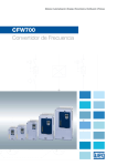
CFW700
Variable Speed Drives
www.weg.net
CFW-700
Designed for controlling squirrel cage three-phase induction motors the new CFW700 is a general
purpose drive that gives costumers the flexibility needed for the control of applications ranging from
simple speed control to more demanding ones as torque control. Since it is included on its control the
CFW700 features Sensor less and Closed loop control as standard feature (factory built). Another
outstanding characteristic we could not leave behind is that by using the internal micro PLC (SoftPLC
factory built), more sophisticated applications like overhead cranes, PCP (Progressive Cavity Pump),
pump jack and many more can be implemented.
Technology
Vectrue Technology® - WEG VARIABLE SPEED DRIVE CONTROL TECHNOLOGY
g
Four control modes in one drive, Linear and adjustable V/f, VVW (Voltage Vector
WEG), Sensorless Vector and closed loop Vector. ( Encoder interface factory built)
g
Sensorless vector control allows for high torque and quick response in open loop,
even at low speeds.
g
Self-tuning function automatically matches VSD with motor – load when on
Sensorless, VVW and closed loop Vector mode.
g
Through adjustable V/f control it is possible to adjust a quadratic V/f curve and that
implies energy saving when quadratic torque loads (e.g.: centrifugal pumps and fans)
are being driven.
Optimal Braking®
WEG FREQUENCY INVERTERS BRAKING TECHNOLOGY
In applications where high inertia and short deceleration
times are involved, a large amount of energy is returned
from the motor to the VSD.
To handle this energy traditional VSDs have to dissipate it
as heat in power resistors, such resistors are usually large
and very expensive also some installation criteria has to be
considered due to their heat dissipation.
As an alternative to the use of braking resistors the
CFW700 features a special braking method in vector
control mode named “Optimal Braking”.
This innovation delivers rated torque with high performance
requiring no resistor.
The graph given below shows a comparison of the braking
torque offered by the different braking methods used.
Braking Torque (%)
100 (%)
TB1
0
0
20%
100%
200%
Typical Braking Torque x Speed Graph for a
10 HP / 7.5 kW motor driven by a CFW700
Dynamic Braking Torque Curve
Optimal Braking Torque Curve
DC Braking Torque Curve
®
Optimal Flux®
WEG TECHNOLOGY FOR THE CONTROL OF HIGH EFFICIENCY
INDUCTION MOTORS APPLIED TO CONSTANT TORQUE LOAD
g Rated torque at very low speed discarding the use for forced
ventilation or even motor oversizing, thus costs are reduced.
g Better performance results can be achieved with the set motor +
VSD, as losses are decreased (tests were conducted based on the
set WEG high efficiency MOTOR + WEG VSD).
2
Frequency Inverter Series - CFW700
www.weg.net
Keypad
The CFW700 comes equipped with a LCD display capable of providing readings for programming, guided start-up and
troubleshooting.
This customized numeric LCD display features the following functionalities:
g LCD display with back light
g Allows adjust programming through menu separate in folders
g Remote mounting for panel assembly solutions ( it can be placed 30m distant from the drive)
Left soft-key: function defined by display
Key for scrolling through menus and perameters and
for modfying perameter content
FWD/REV Selection
Star Key
Local / Remote Selection
Stop Key
JOG Key
Remote Keypad
The Keypad can be remote assembled by using this configuration, degree of protection IP56 can be achieved.
Frequency Inverter Series - CFW700
3
www.weg.net
Allows for showing 3 variables at once through three viewing modes
Inverter Status
Auxiliar Display
Menu (parameters
group selection)
only one
parameters group
is shown each
time.
Units of Measurement
(refers to the main
display value)
Variable Monitoring Bar
Main Display
Viewing Modes
Monitoring Mode
4
Frequency Inverter Series - CFW700
Programming Mode
www.weg.net
Simplicity
The new CFW700 was designed based on the plug and play technology concept where by plugging in
expansion modules hardware and software recognize it automatically. Also this feature allows for easy
installation and safe operation with no need for additional configuration.
Slot 3 – Communication Module ( optional)
Slot 5 –Flash Module ( optional)
Frequency Inverter Series - CFW700
5
www.weg.net
Technical Features
Main parts
Frames A, B and C
Rear part of the inverter
(external part for flange mounting)
Flash memory module (not included)
Control accessory module
Mounting supports
(for through the wall
mounting)
Front cover
Fan with mounting support
CC700 control board
Keypad
Status LED
6
Frequency Inverter Series - CFW700
www.weg.net
Technical Features
Main parts
Frames D and E
Flash memory module (not included)
CC700 control board
Control accessory module
Mounting supports
(for through the wall mounting)
Status LED
Keypad
Rear part of the inverter (external
part for plange mounting)
Control rack cover
Holsting eye (only on frame E)
Fan with mounting support
Bottom front cover
Frequency Inverter Series - CFW700
7
www.weg.net
Technical Features
1.1 to 2.2kW - 1.5 to 3HP
200-240V - Single-phase
g
1.1 to 55kW - 1.5 to 75HP
220-240V - Three-phase
g
1.5 to 132kW - 2 to 175HP
380-480V - Three-phase
g
Very compact product gives flexibility for lack of space when panel mounted
High accuracy and reliability for speed and torque control
g
Hardware robustness
g
g
Control Terminal
DI8
DI7
DI6
DI5
+24V
GND(24V)
DO5
>300 Ω
>300 Ω
RL1-NA
>300 Ω
RL1-C
RL1-NF
++ +
Frequency Inverter Series - CFW700
DI4
DI3
DI2
DI1
GND(24V)
+24V
AGND (24V)
AO2
AGND (24V)
rpm
rpm
DO4
DO3
DO2
>300 Ω
B - RS485
A - RS485
GND-ENC
Z
Z
AL2-
AO1
REF-
Al1-
Al1+
≥5 kΩ
AI2+
B
B
A
A
+5V-ENC
REF+
8
COM
Z
Active high digital inputs
Brown
Grey
Z
B
Pink
Yellow
Green
B
A
Red
A
+V
Blue
White
GND
++ +
Linedrive encoder or push-pull
www.weg.net
Technical Features
2
1
DC+
BR
1
DC-
1 = DC busbar connection
2 = Connection for braking resistor
Filtro C3 (*)
(available for
models
CFW700...C3...)
Precharge
R/L1/L
S/L2/N
T/L3
U/T1
V/T2
PE
Braking IGBT (available
in CFW700...DB...inverters)
Three-phase
rectifier
DC link capacitor Bank
W/T3
DC link chokes
Power
network
POWER
Motor
Inverter
with IGBT
transistors
RFI Filter
Feedbacks:
- Voltages
- Current
PE
PC
CONTROL
Power Supplies for electronics and interfaces
between power and control.
RS485
Software
Superdrive G2
Software WLP
Accessories
MMI 3 (remote)
COMM 1
(Slot 3 Green)
HMI 3
(Slot 4 Anybus)
CC700
Digital Inputs
( DI1 to DI8)
Control
Card
with
32-bit
RISC
CPU
Analog Inputs
(AI1 and AI2)
Analog Outputs
(AO1 and AO2)
Digital Outputs
DO1 (RL1)
FLASH
Memory
Module
(Slot 5)
Digital Outputs
DO2 to DO5
3 = Keypad
(*) The capacitor to the ground of the C3 filter must be disconnected for IT networks
Notes:
1)Diode type rectifier bridge
2) Standard for frame sizes A to D
3)RFI filter factory built for frame size E
Frequency Inverter Series - CFW700
9
www.weg.net
Technical Features
Integrated options for the product
Built-in DC link Reactor
Allows the VSD to be installed in any network (No
restriction for Power supply impedance)
g Typical Power factor (PF) for steady condition:
g 0.94 for Three-phase models
g0.70 for Single-phase and Single/Three-phase
g models fed from Single-phase Power supply
g Displacement Power factor > 0.98
g
It meets 61000-3-12 standard (Limits for Harmonic
currents)
g No need for an extra line reactor
g
Encoder Interface
For applications requiring closed loop control the
encoder module is available at the control terminals.
g
No need for external power supply for the encoder
module( 5Vcc)
g
5V Line drive or push pull types can be used
g
RS-485 port Embedded
Modbus-RTU communication protocol ready
g
I/Os capability
8 Digital Inputs / 5 Digital Outputs
g 2 Analog Inputs / 2 Analog Outputs
g
Common Dc bus Connection
Very known in multi motors application the possibility
for feeding CFW700 (AC drive) with DC voltage gives
flexibility to the product as well as brings the benefit
for energy savings. By sharing a common DC bus in
some applications the energy consumption can be
lowered as the power needed to run any of the motors
can be drawn from the stored energy at the VSD DC
link.
Note: An external pre-charge circuit must be added to each of the
VSDs.
Thermal Management
g
The possibility for monitoring heat sink and inside
air temperature ensures protection to critical
components e.g. IGBTs and control board.
g
Fans installed closed to heatsink are turned on and
off depending on the temperature of power
modules.
g
Readings of fan operation hours can be analyzed
through parameters as well as alarm or fault
messages are displayed.
g
Easy removal of fans makes maintenance and or
replacement a lot faster.
10
Frequency Inverter Series - CFW700
Supply Network
Single DC Link
General Input
Rectifier Unit
CFW700
1
n
2
3
4
www.weg.net
Technical Features
Drive Features
Multi-speed: Up to 8 preset speeds can be programmed
g
PID regulation: Eliminates the use of an external controller for closed loop control, thus great
performance of speed and torque can be achieved.
g
Ride Through: Embedded in the CFW700 control this function avoids the drive from tripping during some
power outage. It uses the kinetic energy stored through a forced deceleration imposed to the load by the
VSD control algorithm.
g
Speed/Torque regulation: Open and closed loop (encoder feedback required).
g
Flying start: It is able to start smoothly a motor connected to a rotating load regardless rotation direction.
g
Control options for DC bus regulation Prevents the drive from tripping when short deceleration time is
required, very demanded for applications with high inertia loads.
g
S ramp: The smoothness at the Starting can be mandatory for process e.g. the beverage industry, by
setting up properly this functionality production losses caused by traditional starting methods can be
avoided.
g
Three-wire Start/Stop control: No retentive contact can command the drive to start/stop the motor.
g
Electronic Potentiometer: The drive keeps increasing motor speed as long as the digital input remains
closed.
g
Skip Frequency: For some applications specific frequencies must be avoided in order to protect the
machine against resonance effect.
g
Motor thermal curve adjustment: The possibility for separate adjustment between motor and drive
allows for a much more effective protection for overload cycles.
g
Copy function: By using the flash memory card MMF-02 parameter settings can be easily stored
ensuring integrity and safety in case of replacement of the drive is needed.
g
Frequency Inverter Series - CFW700
11
www.weg.net
Soft PLC
The new CFW700 incorporates PLC functionalities by means of a factory built micro PLC named Soft PLC. This extra tool
gives more flexibility to the product as well as allows the user for developing his own application through a RS-485 port
available at the control terminal. The Soft PLC features the following characteristics:
g
g
g
g
A
ccess to CFW700 I/Os and parameters
LC mathematics and Control Blocks
P
A
llows user password
U
ser can save software in the memory flash card to be downloaded into other VSDs.
Free of charge Software
WLP (WEG ladder programmer)
Software Designed for development of user
application through the micro PLC embedded
in the CFW700 hardware.
The WLP tool features the following capabilities:
Ladder programming
PLC, math and control blocks are available
g Access to all CFW700 parameters
g On-line monitoring as well as help topics
g RS-485 connection with the drive
g 49 user parameters can be individually
accessed allowing for creation of a variety
of applications.
g
g
Software superdrive G2
It is a windows-based Software designed for the
programming, commanding and monitoring of
WEG VSDs.
The following features the user can benefit from:
Automatic CFW700 recognition
CFW700 parameters monitoring
g Off-line/On-line change of parameters
g Reports can be created
g Backup of parameters
g Start/Stop command as well as speed reference
can be sent to the drive.
g
g
12
Frequency Inverter Series - CFW700
www.weg.net
Accessories
Blank cover – HMID - 011
Used when there is no need for keypad
Remote keypad frame – RHMIF-02
Used when remote keypad is needed, it
can be installed at the panel door as well
as machine console. IP 56 degree of protection.
Communication Modules
CAN-01 ( CANopen and DeviceNet)
Profibus DP-01 ( Profibus DP-V1)
Flash Memory module MMF - 02
This module allows for backup of VSD parameters
ensuring the programming to be safely stored. Also
it makes possible the programming to be passed
on to other VSDs on the same plant avoiding repetitive
programming. The Soft PLC applicative can also be store
into this memory.
1
These options must be provided already installed in the CFW700 (please see coding on page 21).
Frequency Inverter Series - CFW700
13
www.weg.net
Accessories
Kit for Shielded Cable
PCSA-01
Shielded cable Kit frame size A
PCSB-01
Shielded cable Kit frame size B
PCSC-01
Shielded cable Kit frame size C
Note:
1) The shielded cable kit for frame Sizes D and E is included to the standard version.
2) For models with RFI filter fitted in shielded cable kit comes as standard.
Enclosures
Standards
Ratings
B
C
D
E
X
IP20
X
X
x
X
IP21
KIP21A-01
KIP21B-01
KIP21C-01
KIP21D-01
-
TYPE 1
KN1A-02
KN1B-02
KN1C-02
X
KN1E-01 / KN1E-02
IEC
NEMA
Frame Sizes
A
( X ) Standard
( - ) NA
Standard
NEMA
Type 1
IEC
Accessory
Composition
KN1A-02
Conduit kit frame size A
KN1B-02
Conduit kit frame size B
KN1C-02
Conduit kit frame size C
KN1E-01
Top cover size E models 105 and 142
KN1E-02
Top Cover + Conduit kit size E models 180 and 211
KIP21A-01
Top cover kit frame size A
KIP21B-01
Top cover kit frame size B
KIP21C-01
Top cover kit frame size C
KIP21D-01
Top cover kit frame size D
Note: In the KN1X-01 Conduit kit (frame sizes A,B and C) power cable shielding is also provided
14
Frequency Inverter Series - CFW700
www.weg.net
Optionals (factory built)
External control power supply 24Vcc
Used mainly for communication networks allowing
data exchange even when there is no power
at the VSD input.(this module must be fed from a power
supply different from the one connected to the VSD).
RFI suppressor filter( for the VSD to be in accordance
with EN 61800-3 and EN 55011)
When properly installed the CFW700 meet
requirements of the electromagnetic compatibility
directive – “ EMC Directive 2004/108/EC”.
For models ranging from size A to D, the RFI filter is
optional and for size E it is included.
Safety Stop (in accordance with EN-954-1 and IEC 62061,
category III)
With this option when the safety circuit is
tripped by external causes the IGBT firing circuit is
deactivated, thus removing power from VSD output.
( pending certification).
Frequency Inverter Series - CFW700
15
www.weg.net
Applications
Pumps and fans
g Precise control of process variables (pressure, flow, temperature, etc.) through a PID regulator superposed to the speed control.
g Optimization of power consumption through speed control with an adjustable V/f curve.
g Possibility of safety and maintenance signaling and alarms of pumps and fans.
g Availability of PID regulators to control other process accessories like valves, dumpers, other VSDs, etc.
Compressors
g Optimization of system pressurization control with energy savings and improvement of compressor efficiency.
g Reduction of motor startup current minimizing wear and tear of the mechanical system avoiding fees charged by the power supplier company.
g Possibility of safety and maintenance signaling and alarms of pressurization system.
g Provides startup system control of other compressor units with an increased efficiency of the pressurization system.
Paper and Cellulose / Wood
g Precise speed and torque control.
g
Flexible hardware programming and confguration, making applications
where syncronism is required easier.
g
Possibility to be integratet in a variety of communication protocols commonly
used in the industry.
g
Provided in a compact design the CFW700 series allows for side by side
assembly.
g Quick and simplified programming.
g Highly reliable and robust.
Chemical and Petrochemical
g Highly reliable and robust.
g Plug-and-play system for additional modules, ensuring greater flexibility in adapting to existing systems.
g
Possibility to be integrated in a variety of communication protocols commonly
used in the industry.
Ironworks and Metallurgy
g Highly precise speed and torque control.
g Large overload capacity (models sized in HD).
g Flexible hardware programming and configuration.
g Possibility to be integrated in a variety of communication protocols mainly used in the industry.
16
Frequency Inverter Series - CFW700
www.weg.net
Drive Ratings
Heavy Duty (HD) Cycle:
g 150% for 60 seconds every 10 minutes
g 200% for 3 seconds every 10 minutes
Normal Duty (ND) Cycle:
g 110% for 60 seconds every 10 minutes
g 150% for 3 seconds every 10 minutes
Sizing a VFD:
The proper way how to size a frequency inverter is by matching its output current with the motor rated current. However,
tables below present the expected motor power for each VSD model.
The purpose of the table below is to be used for guidance as motor rated current may vary with number of poles and
manufacturer.
Note: Motor power stated on this table is based on IEC standard for IV poles motor.
Motor Voltage 220V and 230V
Power
Supply
1/3Ø
1Ø
Model
3Ø
200-240 V
3Ø
220230V
IEC
50Hz
220V
230V
kW
1.1
1.5
2.2
1.1
1.5
1.5
2.2
3
4
5.5
7.5
9.2
11
15
18.5
22
30
37
55
55
Normal Duty
(ND)
CFW700A06POS2
CFW700A07POS2
CFW700A10POS2
CFW700A06POB2
CFW700A07POB2
CFW700A07POT2
CFW700A10POT2
CFW700A13POT2
CFW700A16POT2
CFW700B24POT2
CFW700B28POT2
CFW700B33POT2
CFW700C45POT2
CFW700C54POT2
CFW700C70POT2
CFW700D86POT2
CFW700D0105POT2
CFW700E0142POT2
CFW700E0180POT2
CFW700E0211POT2
A
6
7
10
6
7
7
10
13
16
24
28
33.5
45
54
70
86
105
142
180
211
NEMA
IEC
50Hz
220V
230V
kW
1.1
1.5
2.2
1.1
1.5
1.1
1.5
2.2
3
5.5
5.5
7.5
9.2
11
15
18.5
22
30
37
55
Heavy Duty
(HD)
60Hz
230V
HP
1.5
2
3
1.5
2
2
3
3
5
7.5
10
10
15
20
25
30
40
50
60
75
A
5
7
10
5
7
5.5
8
11
13
20
24
28
36
45
56
70
86
115
142
180
NEMA
60Hz
230V
HP
1
2
3
1
2
1
2
3
3
5
7.5
10
10
15
20
25
30
40
50
60
Motor Voltage 380V and 460V
Model
3Ø
380-480 V
Power
Supply
CFW700A03P6T4
CFW700A05P0T4
CFW700A07P0T4
CFW700A10P0T4
CFW700A13P5T4
CFW700B17P0T4
CFW700B24P0T4
CFW700B31P0T4
CFW700C38P0T4
CFW700C45P0T4
CFW700C58P5T4
CFW700D70P5T4
CFW700D88P0T4
CFW700E0105T4
CFW700E0142T4
CFW700E0180T4
CFW700E0211T4
Normal
Duty
(ND)
A
3.6
5
7
10
13.5
17
24
31
38
45
58.5
70.5
88
105
142
180
211
IEC
50Hz
380V
415V
kW
1.5
2.2
3
4
5.5
7.5
11
15
18.5
22
30
37
45
55
75
90
110
NEMA
60Hz
440V
460V
HP
2
3
4
7.5
10
12.5
15
20
30
30
40
50
75
75
100
150
175
60Hz
460V
HP
2
3
3
5
7.5
10
15
20
25
30
40
50
60
75
100
150
150
IEC
Heavy Duty
(HD)
A
3.6
5
5.5
10
11
13.5
19
25
33
38
47
61
73
88
115
142
180
50Hz
380V
415V
kW
1.5
2.2
2.2
4
4
5.5
9.2
11
15
18.5
22
30
37
45
55
75
90
NEMA
60Hz
440V
460V
HP
2
3
3
7.5
7.5
10
12.5
15
25
30
30
50
60
75
75
100
150
Frequency Inverter Series - CFW700
60Hz
460V
HP
2
3
3
5
7.5
7.5
10
15
20
25
30
40
50
60
75
100
150
17
www.weg.net
Dimensions, Weight and Temperature
NEMA 1
Model
Frame
Size
IP20 / IP21
IP20
Dimensions mm
(in)
H
W
D
H
W
D
NEMA 1 / IP21
Maximum Surronding Air Temperature with no
derating °C (°F) _ ND/HD
CFW700A06POS2
50 (122)_ND/HD
50 (122)_ND/HD
CFW700A07POS2
50 (122)_ND/HD
45 (113)_ND/HD
CFW700A10POS2
50 (122)_ND/HD
50 (122)_ND/HD
CFW700A06POB2
50 (122)_ND/HD
50 (122)_ND/HD
50 (122)_ND/HD
45 (113)_ND/HD
50 (122)_ND/HD
45 (113)_ND/HD
CFW700A10POT2
50 (122)_ND/HD
50 (122)_ND/HD
CFW700A13POT2
45 (113)_ND
50 (122)_HD
45 (113)_ND
50 (122)_HD
CFW700A16POT2
50 (122)_ND/HD
50 (122)_ND/HD
CFW700B24POT2
45 (113)_ND/HD
40 (104)_ND/HD
50 (122)_ND/HD
50 (122)_ND/HD
50 (122)_ND/HD
45 (113)_ND
50 (122)_HD
CFW700A07POB2
CFW700A07POT2
CFW700B28POT2
A
B
305
(12.02)
351
(13.82)
CFW700C54POT2
C
CFW700C70POT2
CFW700D86POT2
CFW700D0105POT2
D
CFW700E0142POT2
CFW700E0180POT2
E
CFW700E0211POT2
227
(8.94)
247
(9.73)
145
(5.71)
227
(8.94)
190
(7.46)
227
(8.94)
293
(11.53)
190
(7.46)
227
(8.94)
448.1
(17.64)
220
(8.67)
293
(11.52)
378
(14.88)
220
(8.67)
293
(11.52)
550
(21.63)
300
(11.81)
305
(12.00)
504
(19.84)
300
(11.81)
305
(12.00)
335
(13.2)
358
(14.1)
620
(24.4)
335
(13.2)
358
(14.1)
CFW700B33POT2
CFW700C45POT2
145
(5.71)
735
(28.94)
828.9
(32.63)
50 (122)_ND/HD
50 (122)_ND/HD
50 (122)_ND/HD
50 (122)_ND/HD
50 (122)_ND/HD
50 (122)_ND/HD
50 (122)_ND/HD
50 (122)_ND/HD
50 (122)_ND/HD
50 (122)_ND/HD
45 (113)_ND/HD
45 (113)_ND/HD
45 (113)_ND/HD
45 (113)_ND/HD
45 (113)_ND/HD
45 (113)_ND/HD
CFW700A03P6T4
50 (122)_ND/HD
50 (122)_ND/HD
CFW700A05P0T4
50 (122)_ND/HD
50 (122)_ND/HD
CFW700A07P0T4
45 (113)_ND
50 (122)_HD
40 (104)_ND
50 (122)_HD
45 (113)_ND/HD
45 (113)_ND/HD
50 (122)_ND/HD
50 (122)_ND/HD
50 (122)_ND/HD
50 (122)_ND/HD
50 (122)_ND/HD
40 (104)_ND
45 (122)_HD
CFW700B31P0T4
50 (122)_ND/HD
50 (122)_ND/HD
CFW700C38P0T4
50 (122)_ND/HD
50 (122)_ND/HD
50 (122)_ND/HD
50 (122)_ND/HD
50 (122)_ND/HD
50 (122)_ND/HD
50 (122)_ND/HD
50 (122)_ND/HD
50 (122)_ND/HD
50 (122)_ND/HD
45 (113)_ND/HD
45 (113)_ND/HD
45 (113)_ND/HD
45 (113)_ND/HD
45 (113)_ND/HD
45 (113)_ND/HD
45 (113)_ND/HD
45 (113)_ND/HD
A
CFW700A10P0T4
305
(12.02)
145
(5.71)
227
(8.94)
247
(9.73)
145
(5.71)
227
(8.94)
CFW700A13P5T4
CFW700B17P0T4
CFW700B24P0T4
CFW700C45P0T4
B
C
CFW700C58P5T4
CFW700D70P5T4
CFW700D88P0T4
D
CFW700E0105T4
CFW700E0142T4
CFW700E0180T4
CFW700E0211T4
E
351
(13.82)
190
(7.46)
227
(8.94)
293
(11.53)
190
(7.46)
227
(8.94)
448.1
(17.64)
220
(8.67)
293
(11.52)
378
(14.88)
220
(8.67)
293
(11.52)
550
(21.63)
300
(11.81)
305
(12.00)
504
(19.84)
300
(11.81)
305
(12.00)
335
(13.2)
358
(14.1)
620
(24.4)
335
(13.2)
358
(14.1)
735
( 28.94)
828.9
( 32.63)
Weight
kg (lb)
Braking IGBT
6.3
(13.9)
Standard
10.4
(22.9)
20.5
(45.2)
32.6
(71.8)
650
(143.3)
Optional
6.3
(13.9)
10.4
(22.9)
Standard
20.5
(45.2)
32.6
(71.8)
650
(143.3)
Optional
H
Note: Weight data is for the VSD as IP20 enclosure, if IP21 and NEMA1 kits are being added the total weight will change. Consult the user manual for additional
information.
D
w
18
Frequency Inverter Series - CFW700
www.weg.net
Mounting Considerations
Innovative design allows the CFW700 to be assembled in three different ways:
Standard Installation
D
C
A
B
Minimum Mounting Clearance with top Cover fitted in
Frame
Size
A mm(in)
B mm(in)
C mm(in)
D mm(in)
A
25(0.98)
25(0.98)
10(0.39)
30(1.18)
B
40(1.57)
45(1.77)
10(0.39)
30(1.18)
C
110(4.33)
130(5.12)
10(0.39)
30(1.18)
D
110(4.33)
130(5.12)
10(0.39)
30(1.18)
E
100(3.94)
250(9.84)
20(0.78)
80(3.15)
Side by side Installation
The possibility for installing CFW700 series with
no space in between allows for panel space
saving.
Note: For side by side assembly option check user manual for further operating
temperature details.
Frequency Inverter Series - CFW700
19
www.weg.net
Mounting Considerations / Panel Assembly
Surface Installation
Airflow
Flange Mounting
( IP-54 rated when mounting the heatsink outside the enclosure)
Airflow
Frame
Size
20
a2 mm(in)
b2 mm(in)
c2 (M)
a3 mm(in)
b3 mm(in)
c3 (M)
d3 mm(in)
e3 mm(in)
A
115(4.53)
250(9.85)
M5
130(5.12)
240(9.45)
M5
135(5.32)
225(8.86)
B
150(5.91)
300(11.82)
M5
175(6.89)
285(11.23)
M5
179(7.05)
271(10.65)
C
150(5.91)
375(14.77)
M6
195(7.68)
365(14.38)
M6
205(8.08)
345(13.59)
D
200(7.88)
525(20.67)
M8
275(10.83)
517(20.36)
M8
285(11.23)
485(19.10)
E
200(7.8)
650(25.6)
M8
275(10.8)
635(25)
M8
315(12.40)
615(24.21)
Frequency Inverter Series - CFW700
www.weg.net
Coding
Model Identification
Product and
Series
Frame size
Rated current
No. of phases
Rated voltage
CFW700
A
03P6
T
4
Braking ¹
Degree of
Protection ¹
Conducted
Emission Level ¹
Safety Stop ²
External Power
Supply for
control
NB
20
C3
Y1
W1
Check table below
NB = Braking IGBT not available
DB = Braking IGBT available
CFW700
20 = IP20
21 = IP21 ( not available for frame size E )
N1 = Nema1 Enclosure
* Check table " enclosures " at chapter " Accessories ".
Blank = with no RFI filter
C3 = According to category 3 of IEC 61800-3 standard
Blank = with no STO function
Y1 = with STO function according to EN 954-1 / ISO 13849-1, category 3
Blank = with no External Power supply board
W1 = Control circuit is supplied through an external 24V power supply
(1) To know what models have this options in the standard product the table below shall be checked
(2)This option is not available for models frame size A with the option for Nema1
Frame
sizes
A
Output Current ( ND)
06P0 = 6.0A
07P0 = 7.0A
Input
Power Supply Voltage
Braking
Degree of protection
Conducted emission level
B = single/three phase power supply
2 = 200...240V
DB
20, 21 or N1
Blank
S = single phase power supply
2 = 200...240V
DB
20, 21 or N1
06P0 = 6.0A
A
07P0 = 7.0A
10P0 = 10A
C3
Blank or C3
07P0 = 7.0A
A
10P0 = 10A
13P0 = 13A
16P0 = 16A
24P0 = 24A
B
20, 21 or N1
28P0 = 28A
2 = 200...240V
33P5 = 33.5A
45P0 = 45A
C
DB
Blank or C3
S = three phase power supply
54P0 = 54A
70P0 = 70A
D
86P0 = 86A
21 or N1
0105 = 105A
0142 = 142A
E
0180 = 180A
2 = 220...230V
NB or DB
20 or N1
C3
B = single/three phase power supply
2 = 200...240V
DB
20, 21 or N1
Blank
S = single phase power supply
2 = 200...240V
DB
20, 21 or N1
0211 = 211A
A
06P0 = 6.0A
07P0 = 7.0A
06P0 = 6A
A
07P0 = 7.0A
10P0 = 10A
C3
Blank or C3
3P6 = 3.6A
05P0 = 5.0A
A
07P0 = 7.0A
10P0 = 10A
13P5 = 13.5A
20, 21 or N1
17P0 = 17A
B
DB
24P0 = 24A
Blank or C3
31P0 = 31A
38P0 = 38A
C
T = three phase power supply
4 = 380...480V
45P0 = 45A
58P5 = 58.5A
D
70P5 = 70.5A
21 or N1
88P0 = 88A
0105 = 105A
E
0142 = 142A
0180 = 180A
NB or DB
20 or N1
C3
0211 = 211A
Frequency Inverter Series - CFW700
21
www.weg.net
Technical Data
Single Phase
Voltage
Three Phase
Single Phase
Power
Voltage and Rating Features
Three Phase
200-220Vac ( +10%-15%)
200-220Vac ( +10%-15%)
380-480Vac ( +10%-15%)
1.5 to 3HP (1.1 to 2.2kW)
1.5 to 75HP (1.1 to 55kW)
2 to 175HP (1.5 to 110kW)
Frequency
50...60Hz (+/-2%_48 to 63Hz)
Displacement factor
Greater than 0.98
Efficiency
Greater than 0.97
Power Factor
0.94 for three phase input at nominal conditional
0.70 for single phase input at nominal conditional
Frequency Range
0 to 3.4x motor rated frequency (P0403). The rated frequency is programable up to 300Hz (V/Hz) and
120Hz(vector mode). Switching Frequency data must be observed for speed limits.
Standard: 5kHz ( A,B,C D frames)
2.5kHz for all 380V models frame E
2.5kHz for frame E 220V models 142/180Amps(ND)
Switching Frequency
2.5kHz for frame E 220V model 211Amps(ND/HD)
5kHz for frame E 220V models 142/180Amps(HD)
Control
Available options for 2.5/5/10kHz( check for derating)
Overload
Normal
Duty(ND)
110% for 1min every 10min
150% for 3s every 10min
Heavy
Duty(HD)
150% for 1min every 10min
200% for 3s every 10min
Aceleration
0 to 999s
Deceleration
0 to 999s
-10 to 50°C (14 to 122°F) for most of models. For operating temperature of each model the table " Dimensions, Weight and
Temperature" shall be checked.
Temperature
-10...60ºC for frames A, B, C and D (up to 45°C without derating for models 13A and 24A/200...240V, 7 and 10A/380...480V
and up to 50°C without derating for the other models) and-10...55°C for frame E (up to 45°C without derating). If derating has
to be considered have 2% current reduction for each °C above the specific operating temperature.
Humidity
5 to 90% with no condensation
Environment
Altitude
Braking Methods
0 to 1000 meters with no derating
Up to 4000 meters with current reduction of 1% for each 100 meters above 1000 meters
Dynamic Braking
Available as standard for frame sizes A,B,C and D. For frame size E "DB" models has to be used. An extra resistor must be
fitted in for dynamic braking capability.
Optimal Braking
There is no need for braking resistor
DC Braking
DC Current applied to motor
Regulation: 1% of rated speed
V/f
Voltage Vector VVW
Sensorless Vector
Speed Variation range 1:20
Regulation: 1% of rated speed
Speed Variation range 1:30
Speed Control Regulation: 0.5% of rated speed
Speed Variation range 1:100
Regulation:+/- 0.1% of rated speed with digital reference
(keypad, serial fieldbus, multispeed)
Regulation:+/- 0.2% of rated speed with 12bits analog input
Performance
Vector with Encoder
( Encoder Interface
built-in)
Sensorless Vector
Range: 10 to 180%
Torque
Control
I/Os
Analog
Relay
Output
Analog
24V power supply
capacity
22
Range: 20 to 180%
Regulation: +/-10% of rated torque (above 3Hz)%
Digital
Inputs
Regulation: +/-5% of rated torque
8 x isolated bidirectional 24V
2 x +/-10V, 11bits + signal(differencial) or 0/4...20mA, 11bits(differencial)
Impedance: 400kΩ for voltage signal / 500Ω for current signal
1 x relay NO/NC contact(240Vac/1A)
4 x open drain (24V/200mA)
2 x 0...10V or 0/4...20mA, 11 bits
(not isolated from inverter ground)
500mA ( available for the user, including I/Os)
Frequency Inverter Series - CFW700
www.weg.net
Technical Data
Modbus-RTU
Communication
RS-485 built-in ( Available at the control terminals)
RS-485 built-in / Superdrive and WLP communication
DeviceNet
CAN-01 ( slot 3)
CANopen
CAN-01 ( slot 3)
Profibus DP
PROFIBUS DP-01 ( slot 3)
UL 508C Power conversion equipment
UL 840 Insulation coordination including clearences and creepage distances for electrical equipment
EN61800-5-1 - Safety requirements electrical, thermal and energy.
EN 50178 - Electronic equipment for use in power installations.
Safety Standards
EN 60204-1 - Safety of machinery. Electrical equipment of machines. Part 1: General requirements. In order to have a machine in conformity
with this regulation, the machine builder is resposible forthe installation of na emergency shutdown device and na equipment for power
disconnection.
EN 60146 (IEC 146) - Semiconductor converters.
EN 61800-2 - Adjustable speed electrical power drive systems - Part 2: General requirements - Rating specifications for low voltage
adjustable frequency A.C. power drive systems
EN 60529 - Degrees of protection provided by enclosures (IP code).
UL 50 - Enclosures for electrical equipment
EN 61800-3 - Adjustable speed electrical power drive systems - Part 3: EMC product standard including specifc test methods.
EN 55011 - Limits and methods of measurement of radio disturbance characteristics of undustrial, scientific and medical(ISM)
radio-frequency equipment.
Mechanical Construccion Standards
Eletromagnetic Compatibility Standards (
EMC)
CISPR 11 - Industrial, scientifc and medical (ISM) radio-frequency equipment – Eletromagnetic disturbance characteristics
- Limits and methods of measurement.
EN 61000-4-2 - Electromagnetic compatibility (EMC) - Part 4: Testing and measurement techniques - Section 2: Eletrostatic
discharge immunity test.
EN 61000-4-3 - Electromagnetic compatibility (EMC) - Part 4: Testing and measurement techniques - Section 3: Radiated, radiofrequency, electromagnetic feld immunity test.
EN 61000-4-4 - Electromagnetic compatibility (EMC) - Part 4: Testing and measurement techniques - Section 4: Electrical fast
transient/burst immunity test.
EN 61000-4-5 - Electromagnetic compatibility (EMC) - Part 4: Testing and measurement techniques - Section 5: Surge immunity test.
EN 61000-4-6 - Electromagnetic compatibility (EMC)- Part 4: Testing and measurement techniques - Section 6: Immunity to conducted
disturbances, induced by radio-frequency fields.
Overcurrent / Short Circuit
Under / Overvoltage in the power section
Phase Loss
VSD thermal Overload ( IGBTs, rectifier and in the eletronics)
Motor thermal overload
Braking resistor overload
Protections
IGBTs overload
Motor overload
Fault / external alarm
CPU failure
Phase-to ground short circuit at the output
Failure at the heatsink fan
Motor Overspeed
Wrong connection of encoder wiring
Frequency Inverter Series - CFW700
23
WEG Worldwide Operations
AUSTRALIA
WEG AUSTRALIA PTY. LTD.
3 Dalmore Drive
Carribean Park Industrial Estate
Scoresby VIC 3179 - Melbourne
Phone: 61 (3) 9765 4600
Fax: 61 (3) 9753 2088
[email protected]
www.weg.net/au
BELGIUM
WEG BENELUX S.A.
Rue de l’Industrie 30 D,
1400 Nivelles
Phone: + 32 (67) 88-8420
Fax: + 32 (67) 84-1748
[email protected]
www.weg.net/be
CHILE
WEG CHILE S.A.
Los Canteros 8600
La Reina - Santiago
Phone: (56-2) 784 8900
Fax: (56-2) 784 8950
[email protected]
www.weg.net/cl
CHINA
WEG (NANTONG) ELECTRIC
MOTOR MANUFACTURING CO.,
LTD.
No. 128# - Xinkai South Road,
Nantong Economic &
Technical Development Zone,
Nantong, Jiangsu Province.
Phone: (86) 0513-85989333
Fax: (86) 0513-85922161
[email protected]
www.weg.net/cn
COLOMBIA
WEG COLOMBIA LTDA
Calle 46A N82 - 54
Portería II - Bodega 7 - San
Cayetano II - Bogotá
Phone: (57 1) 416 0166
Fax: (57 1) 416 2077
[email protected]
www.weg.net/co
DENMARK
WEG Scandinavia Denmark
Sales Office of WEG
Scandinavia AB
Anelysparken 43B
True
8381 Tilst – Denmark
Phone: +45 86 24 22 00
Fax : +45 86 24 56 88
[email protected]
www.weg.net/se
FRANCE
WEG FRANCE SAS
ZI de Chenes – Le Loup
13 Rue du Morellon – BP 738
38297 Saint Quentin Fallavier
Phone: +33 (0) 4 74 99 11 35
Fax: +33 (0) 4 74 99 11 44
[email protected]
www.weg.net/fr
GERMANY
WEG GERMANY GmbH
Industriegebiet Türnich 3
Geigerstraße 7
50169 Kerpen-Türnich
Phone: +49 (0)2237/9291-0
Fax: +49 (0)2237/9292-200
[email protected]
www.weg.net/de
GHANA
ZEST ELECTRIC GHANA
LIMITED - WEG Group
15, Third Close Street Airport
Residential Area, Accra PMB CT
175, Cantonments
Phone: 233 30 27 664 90
Fax: 233 30 27 664 93
[email protected]
www.zestghana.com.gh
INDIA
WEG Electric (India) Pvt.
Ltd.
#38, Ground Floor, 1st Main
Road, Lower Palace Orchards,
Bangalore – 560 003
Phone(s): +91-80-4128 2007
+91-80-4128 2006
Fax: +91-80-2336 7624
[email protected]
www.weg.net/in
ITALY
WEG ITALIA S.R.L.
V.le Brianza 20 - 20092 - Cinisello
Balsamo - Milano
Phone: (39) 02 6129-3535
Fax: (39) 02 6601-3738
[email protected]
www.weg.net/it
JAPAN
WEG ELECTRIC MOTORS
JAPAN CO., LTD.
Yokohama Sky Building 20F,
2-19-12 Takashima,
Nishi-ku, Yokohama City,
Kanagawa, Japan 220-001
Phone: (81) 45 440 6063
[email protected]
www.weg.net/jp
MEXICO
WEG MEXICO, S.A. DE C.V.
Carretera Jorobas-Tula Km. 3.5,
Manzana 5, Lote 1
Fraccionamiento Parque
Industrial - Huehuetoca,
Estado de México - C.P. 54680
Phone: + 52 (55) 5321 4275
Fax: + 52 (55) 5321 4262
[email protected]
www.weg.net/mx
NETHERLANDS
WEG NETHERLANDS
Sales Office of
WEG Benelux S.A.
Hanzepoort 23C
7575 DB Oldenzaal
Phone: +31 (0) 541-571080
Fax: +31 (0) 541-571090
[email protected]
www.weg.net/nl
PORTUGAL
WEG EURO - INDÚSTRIA
ELÉCTRICA, S.A.
Rua Eng. Frederico Ulrich
Apartado 6074
4476-908 - Maia
Phone: +351 229 477 705
Fax: +351 229 477 792
[email protected]
www.weg.net/pt
RUSSIA
WEG RUSSIA
Russia, 194292, St. Petersburg,
Prospekt Kultury 44, Office 419
Phone: +7(812)363-21-72
Fax: +7(812)363-21-73
[email protected]
www.weg.net/ru
SOUTH AFRICA
ZEST ELECTRIC MOTORS
(PTY) LTD. WEG Group
47 Galaxy Avenue, Linbro
Business Park - Gauteng Private
Bag X10011 - Sandton, 2146
Johannesburg
Phone: (27-11) 723-6000
Fax: (27-11) 723-6001
[email protected]
www.zest.co.za
SPAIN
WEG IBERIA S.L.
Avenida de la Industria,25
28823 Coslada - Madrid
Phone: (34) 916 553 008
Fax : (34) 916 553 058
[email protected]
www.weg.net/es
WEG Equipamentos Elétricos S.A.
International Division
Av. Prefeito Waldemar Grubba, 3000
89256-900 - Jaraguá do Sul - SC - Brazil
Phone:55 (47) 3276-4002
Fax: 55 (47) 3276-4060
www.weg.net
SINGAPORE
WEG SINGAPORE PTE LTD
159, Kampong Ampat,
#06-02A KA PLACE.
Singapore 368328.
Phone: +65 6858 9081
Fax: +65 6858 1081
[email protected]
www.weg.net/sg
SWEDEN
WEG SCANDINAVIA AB
Box 10196
Verkstadgatan 9
434 22 Kungsbacka
Phone: (46) 300 73400
Fax: (46) 300 70264
[email protected]
www.weg.net/se
UK
WEG ELECTRIC
MOTORS (U.K.) LTD.
28/29 Walkers Road
Manorside Industrial Estate
North Moons Moat - Redditch
Worcestershire B98 9HE
Phone: 44 (0)1527 596-748
Fax: 44 (0)1527 591-133
[email protected]
www.weg.net/uk
UNITED ARAB EMIRATES
WEG MIDDLE EAST FZE
JAFZA – JEBEL ALI FREE ZONE
Tower 18, 19th Floor,
Office LB 18 1905
P.O. Box 262508 - Dubai
Phone: +971 (4) 8130800
Fax: +971 (4) 8130811
[email protected]
www.weg.net/ae
USA
WEG ELECTRIC CORP.
6655 Sugarloaf Parkway,
Duluth, GA 30097
Phone: 1-678-249-2000
Fax: 1-770-338-1632
[email protected]
www.weg.net/us
VENEZUELA
WEG INDUSTRIAS VENEZUELA C.A.
Avenida 138-A
Edificio Torre Banco Occidental de
Descuento, Piso 6 Oficina 6-12
Urbanizacion San Jose de Tarbes
Zona Postal 2001
Valencia, Edo. Carabobo
Phone(s): (58) 241 8210582
(58) 241 8210799
(58) 241 8211457
Fax: (58) 241 8210966
[email protected]
www.weg.net/ve
Cod: 50030009 | Rev: 01 | Date (m/y): 02/2011
The values shown are subject to change without prior notice.
ARGENTINA
WEG EQUIPAMIENTOS
ELECTRICOS S.A.
(Headquarters San
Francisco-Cordoba)
Sgo. Pampiglione 4849
Parque Industrial San Francisco
2400 - San Francisco
Phone: +54 (3564) 421484
Fax: +54 (3564) 421459
[email protected]
www.weg.net/ar