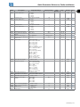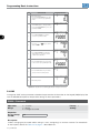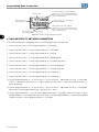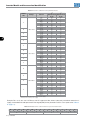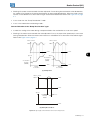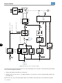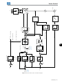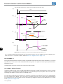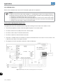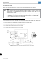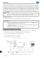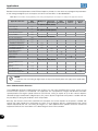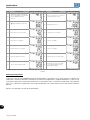
1
Motors | Automation | Energy | Transmission & Distribution | Coatings Frequency Inverter CFW700 Programming Manual Programming Manual Series: CFW700 Language: English Document Number: 10001006882 / 02 Software Version: 2.0X Publication Date: 09/2014 Summary QUICK PARAMETER REFERENCE, FAULTS AND ALARMS..................0-1 1 SAFETY NOTICES .................................................................................. 1-1 1.1 SAFETY NOTICES IN THIS MANUAL.............................................................................................1-1 1.2 SAFETY NOTICES ON THE PRODUCT..........................................................................................1-1 1.3 PRELIMINARY RECOMMENDATIONS...........................................................................................1-1 2 GENERAL INFORMATION....................................................................... 2-1 2.1 ABOUT THIS MANUAL....................................................................................................................2-1 2.2 TERMINOLOGY AND DEFINITIONS..............................................................................................2-1 2.2.1 Terms and Definitions Used in the Manual........................................................................2-1 2.2.2 Numerical Representation.................................................................................................. 2-3 2.2.3 Symbols for the Parameter Properties Description........................................................ 2-3 3 ABOUT THE CFW700..............................................................................3-1 4 KEYPAD (HMI)..........................................................................................4-1 5 PROGRAMMING BASIC INSTRUCTIONS..............................................5-1 5.1 PARAMETERS STRUCTURE.......................................................................................................... 5-1 5.2 GROUPS ACCESSED IN THE OPTION MENU IN THE MONITORING MODE........................... 5-1 5.3 PASSWORD SETTING IN P0000.................................................................................................... 5-1 5.4 HMI................................................................................................................................................... 5-2 5.5 ENGINEERING UNITS FOR SOFTPLC.......................................................................................... 5-5 5.6 DISPLAY INDICATIONS IN THE MONITORING MODE SETTINGS............................................ 5-9 5.7 INCOMPATIBILITY BETWEEN PARAMETERS ...........................................................................5-10 6 INVERTER MODEL AND ACCESSORIES IDENTIFICATION ................6-1 6.1 INVERTER DATA ............................................................................................................................ 6-1 7 STARTING-UP AND SETTINGS.............................................................. 7-1 7.1 BACKUP PARAMETERS..................................................................................................................7-1 8 AVAILABLE CONTROL TYPES...............................................................8-1 9 SCALAR CONTROL (V/f).........................................................................9-1 9.1 V/f CONTROL................................................................................................................................... 9-2 9.2 ADJUSTABLE V/f CURVE............................................................................................................... 9-5 9.3 V/f CURRENT LIMITATION ............................................................................................................ 9-6 9.4 V/f DC VOLTAGE LIMITATION........................................................................................................ 9-8 9.5 START-UP IN THE V/f CONTROL MODE.....................................................................................9-11 9.6 ENERGY SAVING...........................................................................................................................9-11 10 V V W CONTROL.................................................................................. 10-1 10.1 V V W CONTROL......................................................................................................................... 10-3 10.2 MOTOR DATA ............................................................................................................................. 10-3 10.3 V V W CONTROL MODE START-UP ......................................................................................... 10-4 11 VECTOR CONTROL............................................................................. 11-1 11.1 SENSORLESS CONTROL AND WITH ENCODER ..................................................................... 11-1 11.2 I/f MODE (SENSORLESS) ...........................................................................................................11-4 Summary 11.3 SELF-TUNING ..............................................................................................................................11-4 11.4 OPTIMAL FLUX FOR SENSORLESS VECTOR CONTROL .....................................................11-5 11.5 TORQUE CONTROL.....................................................................................................................11-6 11.6 OPTIMAL BRAKING .................................................................................................................... 11-7 11.7 MOTOR DATA ...............................................................................................................................11-8 11.7.1 Adjustment of the Parameters P0409 to P0412 Based on the Motor Data Sheet.... 11-12 11.8 VECTOR CONTROL .................................................................................................................. 11-13 11.8.1 Speed Regulator ............................................................................................................. 11-13 11.8.2 Current Regulator ........................................................................................................... 11-15 11.8.3 Flux Regulator ................................................................................................................. 11-15 11.8.4 I/f Control ........................................................................................................................ 11-17 11.8.5 Self-Tuning........................................................................................................................ 11-18 11.8.6 Torque Current Limitation..............................................................................................11-22 11.8.7 Supervision of Motor Real Speed..................................................................................11-23 11.8.8 DC Link Regulator...........................................................................................................11-23 11.9 START-UP IN THE VECTOR MODES SENSORLESS AND WITH ENCODER........................11-25 12 FUNCTIONS COMMON TO ALL THE CONTROL MODES................ 12-1 12.1 RAMPS..........................................................................................................................................12-1 12.2 SPEED REFERENCES ............................................................................................................... 12-3 12.3 SPEED LIMITS ........................................................................................................................... 12-5 12.4 ZERO SPEED LOGIC.................................................................................................................. 12-6 12.5 FLYING START/RIDE-THROUGH................................................................................................12-7 12.5.1 V/f or V V W Flying Start.................................................................................................... 12-8 12.5.2 Vector Flying Start........................................................................................................... 12-8 12.5.2.1 P0202 = 4................................................................................................................ 12-8 12.5.2.2 P0202 = 5...............................................................................................................12-10 12.5.3 VVW or V/f Ride-Through...............................................................................................12-10 12.5.4 Vector Ride-Through.......................................................................................................12-12 12.6 DC BRAKING..............................................................................................................................12-14 12.7 SKIP SPEED ..............................................................................................................................12-18 12.8 SEARCH OF ZERO OF THE ENCODER...................................................................................12-19 13 DIGITAL AND ANALOG INPUTS AND OUTPUTS.............................. 13-1 13.1 I/O CONFIGURATION .................................................................................................................13-1 13.1.1 Analog Inputs .....................................................................................................................13-1 13.1.2 Analog Outputs................................................................................................................. 13-5 13.1.3 Digital Inputs..................................................................................................................... 13-9 13.1.4 Digital Outputs/Relays....................................................................................................13-14 13.1.5 Frequency Input.............................................................................................................. 13-22 13.2 LOCAL AND REMOTE COMMAND......................................................................................... 13-23 14 DYNAMIC BRAKING............................................................................ 14-1 15 FAULTS AND ALARMS........................................................................ 15-1 15.1 MOTOR OVERLOAD PROTECTION............................................................................................15-1 15.2 MOTOR OVERTEMPERATURE PROTECTION......................................................................... 15-2 15.3 PROTECTIONS............................................................................................................................ 15-3 16 READ ONLY PARAMETERS................................................................ 16-1 16.1 FAULT HISTORY.......................................................................................................................... 16-8 17 COMMUNICATION .............................................................................. 17-1 17.1 RS-485 SERIAL INTERFACE....................................................................................................... 17-1 17.2 CAN INTERFACE – CANOPEN/DEVICENET.............................................................................. 17-1 Summary 17.3 PROFIBUS DP INTERFACE.........................................................................................................17-2 17.4 COMMUNICATION STATES AND COMMANDS........................................................................17-3 18 SOFTPLC.............................................................................................. 18-1 19 APPLICATIONS.................................................................................... 19-1 19.1 INTRODUCTION...........................................................................................................................19-1 19.2 PID CONTROLLER APPLICATION..............................................................................................19-1 19.2.1 Description and Definitions..............................................................................................19-1 19.2.2 PID Operation................................................................................................................... 19-4 19.2.3 Sleep Mode........................................................................................................................19-7 19.2.4 Monitoring Mode Screens................................................................................................19-7 19.2.5 Connection of a 2-Wire Transducer............................................................................... 19-8 19.2.6 Academic PID................................................................................................................... 19-8 19.2.7 Parameters........................................................................................................................ 19-9 19.3 ELECTRONIC POTENTIOMETER APPLICATION (EP)............................................................19-15 19.3.1 Description and Definitions ...........................................................................................19-15 19.3.2 Operation..........................................................................................................................19-17 19.3.3 Parameters.......................................................................................................................19-19 19.4 MULTISPEED APPLICATION................................................................................................... 19-20 19.4.1 Description and Definitions .......................................................................................... 19-20 19.4.2 Operation Setup............................................................................................................. 19-21 19.4.3 Parameters...................................................................................................................... 19-24 19.5 3-WIRE START/STOP COMMAND APPLICATION................................................................. 19-27 19.5.1 Description and Definitions........................................................................................... 19-27 19.5.2 Operation Setup............................................................................................................. 19-28 19.5.3 Parameters...................................................................................................................... 19-30 19.6 FORWARD/REVERSE RUN APPLICATION............................................................................. 19-31 19.6.1 Description and Definitions........................................................................................... 19-31 19.6.2 Operation Setup............................................................................................................. 19-32 19.6.3 Parameters...................................................................................................................... 19-34 19.7 COMBINED SPECIAL FUNCTIONS ........................................................................................ 19-35 19.7.1 Descriptions and Definitions......................................................................................... 19-35 19.7.2 PID2 Controller Function.............................................................................................. 19-36 19.7.2.1 Start-Up................................................................................................................ 19-38 19.7.2.2 Monitoring Mode Screen .................................................................................. 19-42 19.7.2.3 Connection of a 2-Wire Transducer ............................................................... 19-42 19.7.2.4 Academic PID2 Controller ................................................................................ 19-42 19.7.2.5 Parameters........................................................................................................... 19-43 19.7.2.5.1 Sleep Mode........................................................................................... 19-53 19.7.3 Multispeed Function ...................................................................................................... 19-58 19.7.3.1 Start-Up ............................................................................................................. 19-59 19.7.3.2 Parameters ......................................................................................................... 19-62 19.7.4 Electronic Potentiometer (EP) Function ...................................................................... 19-65 19.7.4.1 Start-Up .............................................................................................................. 19-66 19.7.4.2 Parameters........................................................................................................... 19-68 19.7.5 Three-Wire Command (Start/Stop) Function ............................................................. 19-69 19.7.5.1 Start-Up.................................................................................................................19-70 19.7.5.2 Parameters............................................................................................................19-73 19.7.6 Forward/Reverse Run Function.....................................................................................19-74 19.7.6.1 Start-Up..................................................................................................................19-75 19.7.6.2 Parameters........................................................................................................... 19-77 19.7.7 Time to keep the Motor Magnetized Function.............................................................19-78 19.7.7.1 Parameters ............................................................................................................19-78 19.7.8 Drive Logic of Mechanical Brake Function.................................................................. 19-79 19.7.8.1 Start-Up .............................................................................................................. 19-80 19.7.8.2 Parameters .......................................................................................................... 19-84 Summary Quick Parameter Reference, Faults and Alarms QUICK PARAMETER REFERENCE, FAULTS AND ALARMS Param. Description Adjustable Range Factory Setting User Setting 0 Prop. Groups Pag. P0000 Access to Parameters 0 to 9999 P0001 Speed Reference 0 to 18000 rpm 0 ro READ 16-1 5-1 16-1 P0002 Motor Speed 0 to 18000 rpm ro READ P0003 Motor Current 0.0 to 4500.0 A ro READ 16-1 P0004 DC Link Voltage (Ud) 0 to 2000 V ro READ 16-2 P0005 Motor Frequency 0.0 to 1020.0 Hz ro READ 16-2 P0006 VFD Status ro READ 16-2 P0007 Motor Voltage 0 = Ready 1 = Run 2 = Undervoltage 3 = Fault 4 = Self-Tuning 5 = Configuration 6 = DC Braking 7 = STO 0 to 2000 V ro READ 16-3 P0009 Motor Torque -1000.0 to 1000.0 % ro READ 16-3 P0010 Output Power 0.0 to 6553.5 kW ro READ 16-4 P0011 Output Cos phi 0.00 to 1.00 ro READ 16-4 P0012 DI8 to DI1 Status ro READ, I/O 13-9 P0013 DO5 to DO1 Status ro READ, I/O 13-14 P0014 AO1 Value Bit 0 = DI1 Bit 1 = DI2 Bit 2 = DI3 Bit 3 = DI4 Bit 4 = DI5 Bit 5 = DI6 Bit 6 = DI7 Bit 7 = DI8 Bit 0 = DO1 Bit 1 = DO2 Bit 2 = DO3 Bit 3 = DO4 Bit 4 = DO5 0.00 to 100.00 % ro READ, I/O 13-5 P0015 AO2 Value 0.00 to 100.00 % ro READ, I/O 13-5 P0018 AI1 Value -100.00 to 100.00 % ro READ, I/O 13-1 P0019 AI2 Value -100.00 to 100.00 % ro READ, I/O 13-1 P0022 Frequency Input 3.0 to 6500.0 Hz ro READ 13-22 P0023 P0028 Software Version Accessories Configuration 0.00 to 655.35 0000h to FFFFh ro ro READ READ 6-1 6-2 P0029 Power Hardware Configuration ro READ 6-2 P0030 IGBTs Temperature Bit 0 to 5 = Rated Current Bit 6 and 7 = Rated Voltage Bit 8 = RFI Filter Bit 9 = Safety Relay Bit 10 = (0)24 V/(1) DC Link Bit 11 = Always 0 Bit 12 = Dyn. Braking IGBT Bit 13 = Special Bit 14 and 15 = Reserved -20.0 to 150.0 °C ro READ 15-3 P0034 Internal Air Temperature -20.0 to 150.0 °C ro READ 15-3 P0036 Heatsink Fan Speed 0 to 15000 rpm ro READ 16-5 P0037 Motor Overload Status 0 to 100 % ro READ 16-5 P0038 Encoder Speed 0 to 65535 rpm ro READ 16-6 P0039 Encoder Pulse Counter 0 to 40000 ro READ 16-6 P0042 Powered Time 0 to 65535 h ro READ 16-6 P0043 Enabled Time 0.0 to 6553.5 h ro READ 16-6 P0044 kWh Output Energy 0 to 65535 kWh ro READ 16-7 P0045 Enabled Fan Time 0 to 65535 h ro READ 16-7 P0048 Present Alarm 0 to 999 ro READ 16-7 P0049 Present Fault 0 to 999 ro READ 16-7 P0050 Last Fault 0 to 999 ro READ 16-8 CFW700 | 0-1 Quick Parameter Reference, Faults and Alarms 0 Param. Description Adjustable Range Factory Setting User Setting Prop. Groups Pag. P0054 Second Fault 0 to 999 ro READ 16-8 P0058 Third Fault 0 to 999 ro READ 16-8 P0062 Fourth Fault 0 to 999 ro READ 16-8 P0066 Fifth Fault 0 to 999 ro READ 16-8 P0090 Last Fault Current 0.0 to 4500.0 A ro READ 16-8 P0091 Last Fault DC Link Voltage 0 to 2000 V ro READ 16-8 P0092 Last Fault Speed 0 to 18000 rpm ro READ 16-9 P0093 Last Fault Reference 0 to 18000 rpm ro READ 16-9 16-9 P0094 Last Fault Frequency 0.0 to 1020.0 Hz ro READ P0095 Last Fault Motor Voltage 0 to 2000 V ro READ 16-9 P0096 Last Fault DIx Status ro READ 16-10 P0097 Last Fault DOx Status ro READ 16-10 P0100 Acceleration Time Bit 0 = DI1 Bit 1 = DI2 Bit 2 = DI3 Bit 3 = DI4 Bit 4 = DI5 Bit 5 = DI6 Bit 6 = DI7 Bit 7 = DI8 Bit 0 = DO1 Bit 1 = DO2 Bit 2 = DO3 Bit 3 = DO4 Bit 4 = DO5 0.0 to 999.0 s 20.0 s BASIC 12-1 P0101 Deceleration Time 0.0 to 999.0 s 20.0 s BASIC 12-1 P0102 Acceleration Time 2 0.0 to 999.0 s 20.0 s P0103 Deceleration Time 2 0.0 to 999.0 s 20.0 s 12-1 P0104 Ramp Type 0 12-2 P0105 1st/2nd Ramp Selection P0120 Speed Reference Backup 1 12-3 12-1 P0121 Keypad Reference 0 = Linear 1 = S Curve 0 = 1st Ramp 1 = 2nd Ramp 2 = DIx 3 = Serial 4 = CO/DN/DP 5 = SoftPLC 0 = Inactive 1 = Active 0 to 18000 rpm 90 rpm 12-3 P0122 JOG/JOG+ Reference 0 to 18000 rpm 150 (125) rpm 150 (125) rpm Vector 12-3 12-4 12-4 10 % cfg 2 cfg 12-2 P0123 JOG- Reference 0 to 18000 rpm P0132 Maximum Overspeed Level 0 to 100 % P0133 Minimum Speed 0 to 18000 rpm 90 (75) rpm P0134 Maximum Speed 0 to 18000 rpm 1800 (1500) rpm P0135 Maximum Output Current 0.2 to 2 x Inom-HD 1.5 x Inom-HD V/f, V V W P0136 Manual Torque Boost 0 to 9 1 V/f P0137 Automatic Torque Boost 0.00 to 1.00 0.00 V/f 9-2 P0138 Slip Compensation -10.0 to 10.0 % 0.0 % V/f 9-3 P0139 Output Current Filter 0.0 to 16.0 s 0.2 s V/f, V V W 9-4 P0142 Maximum Output Voltage 0.0 to 100.0 % 100.0 % cfg, Adj 9-5 12-5 BASIC 12-5 BASIC 12-5 BASIC 9-6 BASIC 9-2 P0143 Intermediate Output Voltage 0.0 to 100.0 % 50.0 % cfg, Adj 9-5 P0144 3 Hz Output Voltage 0.0 to 100.0 % 8.0 % cfg, Adj 9-5 P0145 Field Weakening Speed 0 to 18000 rpm 1800 rpm cfg, Adj 9-5 P0146 Intermediate Speed 0 to 18000 rpm 900 rpm cfg, Adj 9-5 P0150 V/f DC Regulation Type 0 9-9 800 V cfg, V/f, VVW V/f, V V W 9-10 1.50 V/f, V V W 9-10 P0151 V/f DC Regulation Level 0 = Ramp Hold 1 = Ramp Acceleration 339 to 1000 V P0152 V/f DC Regulation P Gain 0.00 to 9.99 P0153 Dynamic Braking Level 339 to 1000 V P0156 100 % Speed Overload Current 0.1 to 1.5 x Inom-ND 0-2 | CFW700 748 V 14-1 1.05 x Inom-ND 15-4 Quick Parameter Reference, Faults and Alarms Param. P0157 Description Adjustable Range P0158 50 % Speed Overload 0.1 to 1.5 x Inom-ND Current 5 % Speed Overload Current 0.1 to 1.5 x Inom-ND P0159 Motor Tripping Class P0160 P0161 Speed Regulation Optimization Speed Proportional Gain 0 = Class 5 1 = Class 10 2 = Class 15 3 = Class 20 4 = Class 25 5 = Class 30 6 = Class 35 7 = Class 40 8 = Class 45 0 = Normal 1 = Saturated 0.0 to 63.9 P0162 Speed Integral Gain 0.000 to 9.999 Factory Setting User Setting Prop. Groups 0.9 x Inom-ND Pag. 15-4 0.65 x Inom-ND 15-4 1 cfg 15-5 0 cfg, Vector 11-13 7.4 Vector 11-13 0.023 Vector 11-13 P0163 LOC Reference Offset -999 to 999 0 Vector 11-14 P0164 REM Reference Offset -999 to 999 0 Vector 11-14 P0165 Speed Filter 0.012 to 1.000 s 0.012 s Vector 11-14 P0166 Speed Differential Gain 0.00 to 7.99 0.00 Vector 11-15 11-15 P0167 Current Proportional Gain 0.00 to 1.99 0.50 Vector P0168 Current Integral Gain 0.000 to 1.999 0.010 Vector 11-15 P0169 Maximum + Torque Current 0.0 to 350.0 % 125.0 % Vector 11-22 P0170 Maximum - Torque Current 0.0 to 350.0 % 125.0 % Vector 11-22 P0175 Flux Proportional Gain 0.0 to 31.9 2.0 Vector 11-16 P0176 Flux Integral Gain 0.000 to 9.999 0.020 Vector 11-16 P0178 Rated Flux 0 to 120 % 100 % Vector 11-16 P0180 Iq* after I/f 0 to 350 % 10 % Sless 11-17 P0182 Speed for I/f Activation 0 to 90 rpm 18 rpm Sless 11-17 P0183 Current in I/f Mode 0 to 9 1 Sless 11-17 P0184 DC Link Regulation Mode 1 cfg, Vector 11-23 800 V Vector 11-24 26.0 Vector 11-25 11-25 P0185 DC Link Regulation Level 0 = With Losses 1 = Without Losses 2 = Enable/Disable DIx 339 to 1000 V P0186 DC Link Proportional Gain 0.0 to 63.9 P0187 DC Link Integral Gain 0.000 to 9.999 0.010 Vector P0190 Maximum Output Voltage 0 to 600 V 440 V Vector P0191 Encoder Zero Search P0192 Encoder Zero Search Status P0200 Password P0202 Control Type P0204 Load/Save Parameters P0205 Main Display Parameter Selection 0 = Inactive 1 = Active 0 = Inactive 1 = Finished 0 = Inactive 1 = Active 2 = Change Password 0 = V/f 60 Hz 1 = V/f 50 Hz 2 = V/f Adjustable 3 = VVW 4 = Sensorless 5 = Encoder 0 = Not Used 1 = Not Used 2 = Reset P0045 3 = Reset P0043 4 = Reset P0044 5 = Load 60 Hz 6 = Load 50 Hz 7 = Load User 1 8 = Load User 2 9 = Save User 1 10 = Save User 2 0 to 1199 11-16 0 0 12-19 ro 1 READ 12-19 HMI 5-2 0 cfg 9-4 0 cfg 7-1 2 HMI 5-3 CFW700 | 0-3 0 Quick Parameter Reference, Faults and Alarms 0 Param. P0206 Description Adjustable Range Factory Setting User Setting Prop. Groups Pag. Secondary Display Parameter Selection Bar Graph Parameter Selection Main Display Scale Factor 0 to 1199 1 HMI 5-3 0 to 1199 3 HMI 5-3 100.0 % HMI 5-3 P0209 Main Display Engineering Unit 3 HMI 5-4 P0210 Main Display Decimal Point 0 HMI 5-4 P0211 Secondary Display Scale Factor Secondary Display Decimal Point 0 = None 1=V 2=A 3 = rpm 4=s 5 = ms 6=N 7=m 8 = Nm 9 = mA 10 = % 11 = °C 12 = CV 13 = Hz 14 = HP 15 = h 16 = W 17 = kW 18 = kWh 19 = H 20 = According to P0510 21 = According to P0512 22 = According to P0514 23 = According to P0516 0 = wxyz 1 = wxy.z 2 = wx.yz 3 = w.xyz 4 = According to P0511 5 = According to P0513 6 = According to P0515 7 = According to P0517 0.1 to 1000.0 % 100.0 % HMI 5-3 0 HMI 5-4 1 HMI 5-5 15 HMI P0207 P0208 P0212 0.1 to 1000.0 % P0213 Bar Full Scale 0 = wxyz 1 = wxy.z 2 = wx.yz 3 = w.xyz 4 = According to P0511 5 = According to P0513 6 = According to P0515 7 = According to P0517 1 to 65535 P0216 HMI Backlighting 0 to 15 P0217 Zero Speed Disable P0219 0 = Inactive 1 = Active (N* and N) 2 = Active (N*) Condition to Leave Zero 0 = Reference or Speed Speed Disable 1 = Reference Delay for Zero Speed Disable 0 to 999 s P0220 LOC/REM Selection Source P0218 0-4 | CFW700 0 = Always LOC 1 = Always REM 2 = LR Key LOC 3 = LR Key REM 4 = DIx 5 = Serial LOC 6 = Serial REM 7 = CO/DN/DP LOC 8 = CO/DN/DP REM 9 = SoftPLC LOC 10 = SoftPLC REM 0 cfg 0 12-7 0s 2 5-5 12-6 12-7 cfg I/O 13-23 Quick Parameter Reference, Faults and Alarms Param. Description P0221 LOC Reference Selection P0222 REM Reference Selection P0223 LOC FWD/REV Selection P0224 LOC Run/Stop Selection P0225 Selection of JOG – LOCAL Situation P0226 REM FWD/REV Selection P0227 REM Run/Stop Selection P0228 P0229 Selection of JOG – REMOTE Situation Stop Mode Selection P0230 Analog Input Dead Zone P0231 AI1 Signal Function P0232 AI1 Gain P0233 AI1 Signal Type P0234 P0235 P0236 Adjustable Range Factory Setting User Setting Prop. Groups Pag. 0 = HMI 1 = AI1 2 = AI2 3 = Sum AIs > 0 4 = Sum AIs 5 = Serial 6 = CO/DN/DP 7 = SoftPLC Refer to the P0221 options 0 cfg I/O 13-23 1 cfg I/O 13-23 0 = Forward 1 = Reverse 2 = FR Key FWD 3 = FR Key REV 4 = DIx 5 = Serial FWD 6 = Serial REV 7 = CO/DN/DP (FWD) 8 = CO/DN/DP (REV) 9 = SoftPLC (FWD) 10 = SoftPLC (REV) 11 = AI2 Polarity 0 = I/O Keys 1 = DIx 2 = Serial 3 = CO/DN/DP 4 = SoftPLC 0 = Inactive 1 = JOG Key 2 = DIx 3 = Serial 4 = CO/DN/DP 5 = SoftPLC Refer to the P0223 options 2 cfg I/O 13-24 0 cfg I/O 13-24 1 cfg I/O 13-25 4 cfg I/O 13-24 0 = I/O Keys 1 = DIx 2 = Serial 3 = CO/DN/DP 4 = SoftPLC Refer to the P0225 options 1 cfg I/O 13-24 2 cfg I/O 13-25 0 = Ramp to Stop 1 = Coast to Stop 2 = Fast Stop 3 = By Ramp with Iq* = 0 4 = Fast Stop with Iq* = 0 0 = Inactive 1 = Active 0 = Speed Reference 1 = N* without Ramp 2 = Maximum Torque Current 3 = SoftPLC 4 = PTC 5 = Application Function 1 6 = Application Function 2 7 = Application Function 3 8 = Application Function 4 9 = Application Function 5 10 = Application Function 6 11 = Application Function 7 12 = Application Function 8 0.000 to 9.999 0 cfg 0 0 I/O 13-1 cfg I/O 13-2 I/O 13-3 cfg I/O 13-4 1.000 0 13-25 AI1 Offset 0 = 0 to 10 V / 20 mA 1 = 4 to 20 mA 2 = 10 V / 20 mA to 0 3 = 20 to 4 mA 4 = -10 V to 10 V -100.00 to 100.00 % 0.00 % I/O 13-3 AI1 Filter 0.00 to 16.00 s 0.00 s I/O 13-3 AI2 Signal Function Refer to the P0231 options I/O 13-2 0 cfg CFW700 | 0-5 0 Quick Parameter Reference, Faults and Alarms 0 Param. Description Adjustable Range P0237 AI2 Gain 0.000 to 9.999 P0238 AI2 Signal Type P0239 AI2 Offset 0 = 0 to 10 V / 20 mA 1 = 4 to 20 mA 2 = 10 V / 20 mA to 0 3 = 20 to 4 mA 4 = -10 V to 10 V -100.00 to 100.00 % P0240 AI2 Filter 0.00 to 16.00 s P0246 Frequency Input Configuration P0251 AO1 Function P0252 AO1 Gain 0 = Off 1 = DI3 2 = DI4 0 = Speed Reference 1 = Total Reference 2 = Real Speed 3 = Torque Current Reference 4 = Torque Current 5 = Output Current 6 = Active Current 7 = Output Power 8 = Torque Current >0 9 = Motor Torque 10 = SoftPLC 11 = PTC 12 = Motor I x t 13 = Encoder Speed 14 = P0696 Value 15 = P0697 Value 16 = Id* Current 17 = Application Function 1 18 = Application Function 2 19 = Application Function 3 20 = Application Function 4 21 = Application Function 5 22 = Application Function 6 23 = Application Function 7 24 = Application Function 8 0.000 to 9.999 P0253 AO1 Signal Type P0254 AO2 Function 0 = 0 to 10 V / 20 mA 1 = 4 to 20 mA 2 = 10 V / 20 mA to 0 3 = 20 to 4 mA Refer to the P0251 options P0255 AO2 Gain 0.000 to 9.999 P0256 AO2 Signal Type 0 = 0 to 10 V / 20 mA 1 = 4 to 20 mA 2 = 10 V / 20 mA to 0 3 = 20 to 4 mA 0-6 | CFW700 Factory Setting User Setting Prop. 1.000 Groups Pag. I/O 13-3 I/O 13-4 0.00 % I/O 13-3 0.00 s I/O 0 0 cfg cfg 13-3 13-22 2 I/O 13-6 1.000 I/O 13-6 I/O 13-8 5 I/O 13-6 1.000 I/O 13-6 I/O 13-8 0 0 cfg cfg Quick Parameter Reference, Faults and Alarms Param. Description Adjustable Range Factory Setting User Setting Prop. Groups Pag. 1 cfg I/O 13-10 P0263 DI1 Function P0264 DI2 Function 0 = Not Used 1 = Run/Stop 2 = General Enable 3 = Fast Stop 4 = FWD/REV 5 = LOC/REM 6 = JOG 7 = SoftPLC 8 = Ramp 2 9 = Speed/Torque 10 = JOG+ 11 = JOG12 = No External Alarm 13 = No External Fault 14 = Reset 15 = Flying Start Disabling 16 = DC Link Regulator 17 = Program. Disabling 18 = Load User 1 19 = Load User 2 20 = Application Function 1 21 = Application Function 2 12 = Application Function 3 23 = Application Function 4 24 = Application Function 5 25 = Application Function 6 26 = Application Function 7 27 = Application Function 8 28 = Application Function 9 29 = Application Function 10 30 = Application Function 11 31 = Application Function 12 Refer to the P0263 options 4 cfg I/O 13-10 P0265 DI3 Function Refer to the P0263 options 0 cfg I/O 13-10 P0266 DI4 Function Refer to the P0263 options 0 cfg I/O 13-10 P0267 DI5 Function Refer to the P0263 options 6 cfg I/O 13-10 P0268 DI6 Function Refer to the P0263 options 8 cfg I/O 13-10 P0269 DI7 Function Refer to the P0263 options 0 cfg I/O 13-10 P0270 DI8 Function Refer to the P0263 options 0 cfg I/O 13-10 CFW700 | 0-7 0 Quick Parameter Reference, Faults and Alarms 0 Param. Description P0275 DO1 Function (RL1) Adjustable Range Factory Setting User Setting Prop. Groups Pag. P0276 DO2 Function 0 = Not Used 1 = N* > Nx 2 = N > Nx 3 = N < Ny 4 = N = N* 5 = Zero Speed 6 = Is > Ix 7 = Is < Ix 8 = Torque > Tx 9 = Torque < Tx 10 = Remote 11 = Run 12 = Ready 13 = No Fault 14 = No F0070 15 = No F0071 16 = No F0006/21/22 17 = No F0051 18 = No F0072 19 = 4-20 mA OK 20 = P0695 Value 21 = Forward 22 = Ride-Through 23 = Pre-Charge OK 24 = Fault 25 = Enabled Time > Hx 26 = SoftPLC 27 = N > Nx / Nt > Nx 28 = F > Fx (1) 29 = F > Fx (2) 30 = STO 31 = No F0160 32 = No Alarm 33 = No Fault/Alarm 34 = Application Function 1 35 = Application Function 2 36 = Application Function 3 37 = Application Function 4 38 = Application Function 5 39 = Application Function 6 40 = Application Function 7 41 = Application Function 8 42 = Self-tuning Refer to the P0275 options 13 cfg I/O 13-15 2 cfg I/O 13-15 P0277 DO3 Function Refer to the P0275 options 1 cfg I/O 13-15 P0278 DO4 Function Refer to the P0275 options 0 cfg I/O 13-15 P0279 DO5 Function Refer to the P0275 options 0 cfg I/O P0281 Fx Frequency 0.0 to 300.0 Hz P0282 Fx Hysteresis P0287 Nx/Ny Hysteresis P0288 Nx Speed P0289 13-15 4.0 Hz 13-19 0.0 to 15.0 Hz 2.0 Hz 13-20 0 to 900 rpm 18 (15) rpm 13-20 0 to 18000 rpm 120 (100) rpm 13-20 Ny Speed 0 to 18000 rpm 1800 (1500) rpm 13-20 P0290 Ix Current 0 to 2 x Inom-ND 1.0 x Inom-ND 13-20 P0291 Zero Speed 0 to 18000 rpm 18 (15) rpm 13-21 P0292 N = N* Band 0 to 18000 rpm 18 (15) rpm 13-21 P0293 Tx Torque 0 to 200 % 100 % 13-21 P0294 Hx Time 0 to 6553 h 4320 h 13-21 0-8 | CFW700 Quick Parameter Reference, Faults and Alarms Param. Description Adjustable Range Factory Setting P0295 ND/HD VFD Rated Current P0296 Line Rated Voltage P0297 Switching Frequency P0298 Application P0299 Starting DC-Braking Time 0=2A/2A 1 = 3.6 A / 3.6 A 2=5A/5A 3=6A/5A 4 = 7 A / 5.5 A 5=7A/7A 6 = 10 A / 8 A 7 = 10 A / 10 A 8 = 13 A / 11 A 9 = 13.5 A / 11 A 10 = 16 A / 13 A 11 = 17 A / 13.5 A 12 = 24 A / 19 A 13 = 24 A / 20 A 14 = 28 A / 24 A 15 = 31 A / 25 A 16 = 33.5 A / 28 A 17 = 38 A / 33 A 18 = 45 A / 36 A 19 = 45 A / 38 A 20 = 54 A / 45 A 21 = 58.5 A / 47 A 22 = 70 A / 56 A 23 = 70.5 A / 61 A 24 = 86 A / 70 A 25 = 88 A / 73 A 26 = 105 A / 86 A 27 = 105 A / 88 A 28 = 142 A / 115 A 29 = 180 A / 142 A 30 = 211 A / 180 A 31 = 2.9 A / 2.7 A 32 = 4.2 A / 3.8 A 33 = 7 A / 6.5 A 34 = 10 A / 9 A 35 = 12 A / 10 A 36 = 17 A / 17 A 37 = 22 A / 19 A 38 = 27 A / 22 A 39 = 32 A / 27 A 40 = 44 A / 36 A 41 = 53 A / 44 A 42 = 63 A / 53 A 43 = 80 A / 66 A 44 = 107 A / 90 A 45 = 125 A / 107 A 46 = 150 A / 122 A 0 = 200 / 240 V 1 = 380 V 2 = 400 / 415 V 3 = 440 / 460 V 4 = 480 V 5 = 500 / 525 V 6 = 550 / 575 V 7 = 600 V 0 = 1.25 kHz 1 = 2.5 kHz 2 = 5.0 kHz 3 = 10.0 kHz 4 = 2.0 kHz 0 = Normal Duty (ND) 1 = Heavy Duty (HD) 0.0 to 15.0 s P0300 Stopping DC-Braking Time 0.0 to 15.0 s 0.0 s P0301 DC-Braking Speed 0 to 450 rpm 30 rpm P0302 DC-Braking Voltage 0.0 to 10.0 % P0303 Skip Speed 1 0 to 18000 rpm User Setting Prop. Groups Pag. ro READ 6-5 According to the inverter model cfg 6-6 According to the inverter model cfg 6-6 0 cfg 6-7 0.0 s V/f, V V W, Sless V/f, V V W, Sless V/f, V V W, Sless V/f, V V W 12-15 2.0 % 600 rpm 12-15 12-17 12-17 12-18 CFW700 | 0-9 0 Quick Parameter Reference, Faults and Alarms 0 Param. Description Adjustable Range Factory Setting User Setting Prop. Groups Pag. P0304 Skip Speed 2 0 to 18000 rpm 900 rpm 12-18 P0305 P0306 Skip Speed 3 Skip Band 0 to 18000 rpm 0 to 750 rpm 1200 rpm 0 rpm 12-18 12-18 P0308 Serial Address 1 to 247 1 NET 17-1 P0310 Serial Baud Rate 1 NET 17-1 P0311 Serial Byte Configuration 1 NET 17-1 P0313 Communication Error Action 0 = 9600 bits/s 1 = 19200 bits/s 2 = 38400 bits/s 3 = 57600 bits/s 0 = 8 bits, no, 1 1 = 8 bits, even, 1 2 = 8 bits, odd, 1 3 = 8 bits, no, 2 4 = 8 bits, even, 2 5 = 8 bits, odd, 2 0 = Off 1 = Ramp Stop 2 = General Disable 3 = Goes to LOC 4 = LOC Keeping Enabled 5 = Causes Fault 0.0 to 999.0 s 1 NET 17-3 P0314 Serial Watchdog P0316 Serial Interface Status P0317 Oriented Start-up P0318 Copy Function MMF P0320 FlyStart/Ride-Through 0.0 s NET 17-1 ro NET 17-1 0 cfg STARTUP 7-2 0 cfg 7-2 0 cfg 12-8 P0321 DC Link Power Loss 0 = Off 1 = On 2 = Watchdog Error 0 = No 1 = Yes 0 = Off 1 = VFD → MMF 2 = MMF → VFD 3 = VFD Synchronization → MMF 4 = MMF Format 5 = SoftPLC Program Copy 6= SoftPLC Program Save 0 = Off 1 = Flying Start 2 = FS / RT 3 = Ride-Through 178 to 770 V 505 V Vector 12-13 P0322 DC Link Ride-Through 178 to 770 V 490 V Vector 12-13 P0323 DC Link Power Back 178 to 770 V 535 V Vector 12-13 P0325 Ride-Through P Gain 0.0 to 63.9 22.8 Vector 12-14 P0326 Ride-Through I Gain 0.000 to 9.999 0.128 Vector 12-14 P0327 FS I/f Current Ramp 0.000 to 1.000 s 0.070 Sless 12-9 P0328 Flying Start Filter 0.000 to 1.000 s 0.085 Sless 12-9 P0329 FS I/f Frequency Ramp 2.0 to 50.0 20.0 Sless 12-9 P0331 Voltage Ramp 0.2 to 60.0 s 2.0 s V/f, V V W 12-11 P0332 Dead Time 0.1 to 10.0 s 1.0 s V/f, V V W 12-11 P0340 Auto-Reset Time 0 to 255 s P0343 Ground Fault Configuration P0344 Current Limit Configuration P0348 Motor Overload Configuration P0349 I x t Alarm Level 0 = Off 1 = On 0 = Hold 1 = Decel. 0 = Off 1 = Fault/Alarm 2 = Fault 3 = Alarm 70 to 100 % P0350 IGBT Overload Configuration 0-10 | CFW700 0 = F, w/ SF rd. 1 = F/A, w/ SF rd. 2 = F, no SF rd. 3 = F/A, no SF rd. 0s 15-8 1 cfg 15-8 1 9-6 1 cfg, V/f, VVW cfg 15-8 85 % cfg 15-9 1 cfg 15-9 Quick Parameter Reference, Faults and Alarms Param. Description P0351 Motor Overtemperature Config. P0352 Fan Control Configuration P0353 IGBTs/Air Overtemp. Config. P0354 Fan Speed Configuration P0355 Config. of Fault F0185 P0356 Dead Time Compensation Adjustable Range 0 = Off 1 = Fault/Alarm 2 = Fault 3 = Alarm 0 = HS-OFF, Int-OFF 1 = HS-ON, Int-ON 2 = HS-CT, Int-CT 3 = HS-CT, Int-OFF 4 = HS-CT, Int-ON 5 = HS-ON, Int-OFF 6 = HS-ON, Int-CT 7 = HS-OFF, Int-ON 8 = HS-OFF, Int-CT 9 = HS-CT, Int -CT * 10 = HS-CT, Int -OFF * 11 = HS-CT, Int -ON * 12 = HS-ON, Int -CT * 13 = HS-OFF, Int -CT * 0 = HS-F/A, Air-F/A 1 = HS-F/A, Air-F 2 = HS-F, Air-F/A 3 = HS-F, Air-F 4 = HS-F/A, Air-F/A * 5 = HS-F/A, Air-F * 6 = HS-F, Air-F/A * 7 = HS-F, Air-F * 0 = Inactive 1 = Fault 0 = Off 1 = On 0 = Inactive 1 = Active 0 to 60 s P0357 Line Phase Loss Time P0358 Encoder Fault Config. P0360 Speed Hysteresis P0361 0.0 to 999.0 s P0372 Time with Speed different from Reference Sless DC Braking Current 0.0 to 90.0 % P0397 Regen. Slip Compensation 0 = Off 1 = F0067 ON 2 = F0079 ON 3 = F0067, F0079 ON 0.0 to 100.0 % P0398 Motor Service Factor 0 = Off 1 = On 1.00 to 1.50 P0399 Motor Rated Efficiency 50.0 to 99.9 % P0400 Motor Rated Voltage 0 to 600 V P0401 Motor Rated Current 0 to 1.3 x Inom-ND P0402 Motor Rated Speed 0 to 18000 rpm P0403 Motor Rated Frequency 0 to 300 Hz Factory Setting User Setting Prop. Groups Pag. 1 cfg 15-10 2 cfg 15-11 0 cfg 15-12 1 cfg 15-12 1 cfg 15-13 1 cfg 15-13 3s 15-13 3 cfg, Enc 15-13 10.0 % Vector 11-23 0.0 s Vector 11-23 40.0 % Sless 12-17 1 cfg, V V W 10-3 1.00 cfg MOTOR 11-9 67.0 % cfg, V V W MOTOR 10-3 440 V cfg MOTOR 11-9 1.0 x Inom-ND cfg MOTOR 11-9 1750 (1458) rpm cfg MOTOR 11-10 60 (50) Hz cfg MOTOR 11-10 CFW700 | 0-11 0 Quick Parameter Reference, Faults and Alarms 0 Param. Description Adjustable Range User Setting Prop. Groups Pag. Motormax-ND cfg MOTOR 11-10 1024 ppr cfg MOTOR 11-11 0 cfg MOTOR 11-11 0.68 cfg, V V W MOTOR 0 cfg, V V W, Vector MOTOR 9-12 10-4 11-18 0.000 ohm cfg, V V W, Vector MOTOR 11-19 MOTOR 11-20 P0404 Motor Rated Power P0405 Encoder Pulse Number P0406 Motor Ventilation P0407 Motor Rated Power Factor P0408 Run Self-Tuning 0 = No 1 = No Rotation 2 = Run for Im 3 = Run for Tm 4 = Estimate Tm P0409 Stator Resistance 0.000 to 9.999 ohm P0410 Magnetization Current 0 to 1.25 x Inom-ND Inom-ND P0411 Leakage Inductance Tr Time Constant 0.00 to 99.99 mH 0.00 mH cfg, Vector MOTOR 11-20 P0412 0.000 to 9.999 s 0.000 s Vector MOTOR 11-20 P0413 Tm Time Constant 0.00 to 99.99 s 0.00 s Vector P0510 Ind. 1 Engineering Unit P0511 Ind. Decimal Point 1 P0512 Ind. Eng. Unit 2 0 = None 1=V 2=A 3 = rpm 4=s 5 = ms 6=N 7=m 8 = Nm 9 = mA 10 = % 11 = °C 12 = CV 13 = Hz 14 = HP 15 = h 16 = W 17 = kW 18 = kWh 19 = H 0 = wxyz 1 = wxy.z 2 = wx.yz 3 = w.xyz See options in P0510 0-12 | CFW700 0 = 0.33 HP 0.25 kW 1 = 0.5 HP 0.37 kW 2 = 0.75 HP 0.55 kW 3 = 1 HP 0.75 kW 4 = 1.5 HP 1.1 kW 5 = 2 HP 1.5 kW 6 = 3 HP 2.2 kW 7 = 4 HP 3 kW 8 = 5 HP 3.7 kW 9 = 5.5 HP 4 kW 10 = 6 HP 4.5 kW 11 = 7.5 HP 5.5 kW 12 = 10 HP 7.5 kW 13 = 12.5 HP 9 kW 14 = 15 HP 11 kW 15 = 20 HP 15 kW 16 = 25 HP 18.5 kW 17 = 30 HP 22 kW 18 = 40 HP 30 kW 19 = 50 HP 37 kW 20 = 60 HP 45 kW 21 = 75 HP 55 kW 22 = 100 HP 75 kW 23 = 125 HP 90 kW 24 = 150 HP 110 kW 25 = 175 HP 130 kW 100 to 9999 ppr Factory Setting 0 = Self-Ventilated 1 = Separated Ventilation 2 = Optimal Flux 3 = Extended Protection 0.50 to 0.99 MOTOR 11-21 0 HMI 5-5 1 HMI 5-6 11 HMI 5-7 Quick Parameter Reference, Faults and Alarms Param. Description P0513 Ind. Decimal Point 2 P0514 Ind. Eng. Unit 3 P0515 Ind. Decimal Point 3 P0516 Ind. Eng. Unit 4 P0517 Ind. Decimal Point 4 P0588 P0589 Maximum Torque Level Level of Minimum Applied Voltage Minimum Speed Level Hysteresis for the Maximum Torque Level P0590 P0591 P0680 Status Word P0681 Motor Speed in 13 Bits P0682 Serial Control Word Adjustable Range 0 = wxyz 1 = wxy.z 2 = wx.yz 3 = w.xyz See options in P0510 0 = wxyz 1 = wxy.z 2 = wx.yz 3 = w.xyz See options in P0510 0 = wxyz 1 = wxy.z 2 = wx.yz 3 = w.xyz 0 to 85 % 40 to 80 % 0 to 18000 rpm 0 to 30 % Factory Setting User Setting Prop. Groups Pag. 1 HMI 5-7 10 HMI 5-8 1 HMI 5-8 13 HMI 5-9 1 HMI 5-9 0% 40 % cfg, V/f cfg, V/f 9-12 9-12 600 (525) rpm 10 % cfg, V/f cfg, V/f 9-13 9-13 Bit 0 = Reserved Bit 1 = Run command Bit 2 = Reserved Bit 3 = Reserved Bit 4 = Fast Stop Bit 5 = 2nd Ramp Bit 6 = Configuration Mode Bit 7 = Alarm Condition Bit 8 = Running Bit 9 = General Enabling Bit 10 = Forward Bit 11 = JOG Bit 12 = Remote Bit 13 = Undervoltage Bit 14 = Reserved Bit 15 = Fault Condition -32768 to 32767 ro NET 17-3 ro NET 17-3 ro NET 17-1 ro NET 17-1 ro NET 17-1 ro NET 17-1 P0683 Serial Speed Reference Bit 0 = Ramp Enable Bit 1 = General Enable Bit 2 = Run Forward Bit 3 = JOG Bit 4 = Remote Bit 5 = 2nd Ramp Bit 6 = Fast Stop Bit 7 = Fault Reset Bit 8 to 15 = Reserved -32768 to 32767 P0684 CO/DN/DP Control Word Refer to the P0682 options P0685 CO/DN/DP Speed Reference - 32768 to 32767 P0695 Settings for the Digital Outputs P0696 P0697 Bit 4 NET 17-3 Value 1 for Analog Outputs Bit 0 = DO1 Bit 1 = DO2 Bit 2 = DO3 Bit 3 = DO4 Bit 4 = DO5 - 32768 to 32767 0 NET 17-3 Value 2 for Analog Outputs - 32768 to 32767 0 NET 17-3 P0700 CAN Protocol 2 NET 17-1 P0701 CAN Address 1 = CANopen 2 = DeviceNet 0 to 127 63 NET 17-1 CFW700 | 0-13 0 Quick Parameter Reference, Faults and Alarms 0 Param. Description Adjustable Range Factory Setting User Setting Prop. Groups Pag. 0 NET 17-1 1 NET 17-1 ro NET 17-1 P0702 CAN Baud Rate P0703 Bus Off Reset P0705 CAN Controller Status P0706 Received CAN Telegrams 0 = 1 Mbps/Auto 1 = Reserved/Auto 2 = 500 Kbps 3 = 250 Kbps 4 = 125 Kbps 5 = 100 Kbps/Auto 6 = 50 Kbps/Auto 7 = 20 Kbps/Auto 8 = 10 Kbps/Auto 0 = Manual 1 = Automatic 0 = Disabled 1 = Auto-baud 2 = CAN Enabled 3 = Warning 4 = Error Passive 5 = Bus Off 6 = No Bus Power 0 to 65535 ro NET 17-1 P0707 Transmitted CAN Telegrams 0 to 65535 ro NET 17-1 P0708 Bus Off Counter 0 to 65535 ro NET 17-1 P0709 Lost CAN Messages 0 to 65535 ro NET 17-1 P0710 DeviceNet I/O Instances 0 NET 17-1 P0711 DeviceNet Reading Word # 3 0 = ODVA Basic 2W 1 = ODVA Extended 2W 2 = Manuf. Spec. 2W 3 = Manuf. Spec. 3W 4 = Manuf. Spec. 4W 5 = Manuf. Spec. 5W 6 = Manuf. Spec. 6W 0 to 1199 0 NET 17-2 P0712 DeviceNet Reading Word # 4 0 to 1199 0 NET 17-2 P0713 DeviceNet Reading Word # 5 0 to 1199 0 NET 17-2 P0714 DeviceNet Reading Word # 6 0 to 1199 0 NET 17-2 P0715 DeviceNet Writing Word # 3 0 to 1199 0 NET 17-2 P0716 DeviceNet Writing Word # 4 0 to 1199 0 NET 17-2 P0717 DeviceNet Writing Word # 5 0 to 1199 0 NET 17-2 P0718 DeviceNet Writing Word # 6 0 to 1199 0 NET 17-2 P0719 DeviceNet Network Status ro NET 17-2 P0720 DeviceNet Master Status ro NET 17-2 P0721 CANopen Com. Status ro NET 17-2 P0722 CANopen Node Status ro NET 17-2 P0740 Profibus Communication Status ro NET 17-2 P0741 Profibus Data Profile 0 = Offline 1 = Online, Not Connected 2 = Online, Connected 3 = Timed-out Connection 4 = Connection Failure 5 = Auto-Baud 0 = Run 1 = Idle 0 = Disabled 1 = Reserved 2 = Com. Enabled 3 = Error Control Enabled 4 = Guarding Error 5 = Heartbeat Error 0 = Disabled 1 = Initialization 2 = Stopped 3 = Operational 4 = Preoperational 0 = Inactive 1 = Access Error 2 = Offline 3 = Configuration Error 4 = Parameterization Error 5 = Clear Mode 6 = Online 0 = PROFIdrive 1 = Manufacturer NET 17-2 0-14 | CFW700 1 Quick Parameter Reference, Faults and Alarms Param. Description Adjustable Range Factory Setting User Setting Prop. Groups Pag. P0742 Profibus Reading # 3 0 to 1199 0 NET 17-2 P0743 Profibus Reading # 4 0 to 1199 0 NET 17-2 P0744 Profibus Reading # 5 0 to 1199 0 NET 17-2 P0745 Profibus Reading # 6 0 to 1199 0 NET 17-2 P0746 Profibus Reading # 7 0 to 1199 0 NET 17-2 P0747 Profibus Reading # 8 0 to 1199 0 NET 17-2 P0748 Profibus Reading # 9 0 to 1199 0 NET 17-2 P0749 Profibus Reading # 10 0 to 1199 0 NET 17-2 P0750 Profibus Writing # 3 0 to 1199 0 NET 17-3 P0751 Profibus Writing # 4 0 to 1199 0 NET 17-3 P0752 Profibus Writing # 5 0 to 1199 0 NET 17-3 P0753 Profibus Writing # 6 0 to 1199 0 NET 17-3 P0754 Profibus Writing # 7 0 to 1199 0 NET 17-3 P0755 Profibus Writing # 8 0 to 1199 0 NET 17-3 P0756 Profibus Writing # 9 0 to 1199 0 NET 17-3 P0757 Profibus Writing # 10 0 to 1199 0 NET 17-3 P0918 Profibus Address 1 to 126 1 NET 17-3 P0922 Profibus Telegram Selection 1 NET 17-3 P0944 Fault Counter 1 = Standard Telegram 1 2 = Telegram 100 3 = Telegram 101 4 = Telegram 102 5 = Telegram 103 6 = Telegram 104 7 = Telegram 105 8 = Telegram 106 9 = Telegram 107 0 to 65535 ro NET 17-3 P0947 Fault Number 0 to 65535 ro NET 17-3 P0963 Profibus Baud Rate ro NET 17-3 P0964 Drive Identification 0 = 9.6 kbit/s 1 = 19.2 kbit/s 2 = 93.75kbit/s 3 = 187.5 kbit/s 4 = 500 kbit/s 5 = Not detected 6 = 1500 kbit/s 7 = 3000 kbit/s 8 = 6000 kbit/s 9 = 12000 kbit/s 10 = Reserved 11 = 45.45 kbit/s 0 to 65535 ro NET 17-3 P0965 Profile Identification 0 to 65535 ro NET 17-3 P0967 Control Word 1 0000h to FFFFh 0000h ro NET 17-3 P0968 Status Word 1 0000h to FFFFh 0000h ro NET 17-3 P1000 SoftPLC Status 0 = No Applicative 1 = Installing App. 2 = Incompatible App. 3 = Stopped Applicative 4 = Applicative Running ro SPLC, READ 18-1 P1001 SoftPLC Command 0 SPLC 18-1 P1002 Scan Cycle Time 0 = Stop Applicative 1 = Run Applicative 2 = Delete Applicative 0.0 to 999.9 ms 18-1 P1003 Applicative Selection 0 cfg 18-2 P1008 P1009 P1010 Lag Error Position Gain SoftPLC Parameter 1 0 = User 1 = PID Controller 2 = EP 3 = Multispeed 4 = 3-Wire Start/Stop 5 = FWD Run/ REV Run 6 = Special Function Set -9999 to 9999 0 to 9999 -32768 to 32767 READ, SPLC SPLC 10 0 ro, Enc Enc cfg SPLC SPLC SPLC 18-2 18-3 18-3 ro CFW700 | 0-15 0 Quick Parameter Reference, Faults and Alarms 0 Param. P1011 P1012 P1013 P1014 P1015 P1016 P1017 P1018 P1019 P1020 P1021 P1022 P1023 P1024 P1025 P1026 P1027 P1028 P1029 P1030 P1031 P1032 P1033 P1034 P1035 P1036 P1037 P1038 P1039 P1040 P1041 P1042 P1043 P1044 P1045 P1046 P1047 P1048 P1049 P1050 P1051 P1052 P1053 P1054 P1055 P1056 P1057 P1058 P1059 Description SoftPLC Parameter 2 SoftPLC Parameter 3 SoftPLC Parameter 4 SoftPLC Parameter 5 SoftPLC Parameter 6 SoftPLC Parameter 7 SoftPLC Parameter 8 SoftPLC Parameter 9 SoftPLC Parameter 10 SoftPLC Parameter 11 SoftPLC Parameter 12 SoftPLC Parameter 13 SoftPLC Parameter 14 SoftPLC Parameter 15 SoftPLC Parameter 16 SoftPLC Parameter 17 SoftPLC Parameter 18 SoftPLC Parameter 19 SoftPLC Parameter 20 SoftPLC Parameter 21 SoftPLC Parameter 22 SoftPLC Parameter 23 SoftPLC Parameter 24 SoftPLC Parameter 25 SoftPLC Parameter 26 SoftPLC Parameter 27 SoftPLC Parameter 28 SoftPLC Parameter 29 SoftPLC Parameter 30 SoftPLC Parameter 31 SoftPLC Parameter 32 SoftPLC Parameter 33 SoftPLC Parameter 34 SoftPLC Parameter 35 SoftPLC Parameter 36 SoftPLC Parameter 37 SoftPLC Parameter 38 SoftPLC Parameter 39 SoftPLC Parameter 40 SoftPLC Parameter 41 SoftPLC Parameter 42 SoftPLC Parameter 43 SoftPLC Parameter 44 SoftPLC Parameter 45 SoftPLC Parameter 46 SoftPLC Parameter 47 SoftPLC Parameter 48 SoftPLC Parameter 49 SoftPLC Parameter 50 Adjustable Range -32768 to 32767 -32768 to 32767 -32768 to 32767 -32768 to 32767 -32768 to 32767 -32768 to 32767 -32768 to 32767 -32768 to 32767 -32768 to 32767 -32768 to 32767 -32768 to 32767 -32768 to 32767 -32768 to 32767 -32768 to 32767 -32768 to 32767 -32768 to 32767 -32768 to 32767 -32768 to 32767 -32768 to 32767 -32768 to 32767 -32768 to 32767 -32768 to 32767 -32768 to 32767 -32768 to 32767 -32768 to 32767 -32768 to 32767 -32768 to 32767 -32768 to 32767 -32768 to 32767 -32768 to 32767 -32768 to 32767 -32768 to 32767 -32768 to 32767 -32768 to 32767 -32768 to 32767 -32768 to 32767 -32768 to 32767 -32768 to 32767 -32768 to 32767 -32768 to 32767 -32768 to 32767 -32768 to 32767 -32768 to 32767 -32768 to 32767 -32768 to 32767 -32768 to 32767 -32768 to 32767 -32768 to 32767 -32768 to 32767 Factory Setting 0 0 0 0 0 0 0 0 0 0 0 0 0 0 0 0 0 0 0 0 0 0 0 0 0 0 0 0 0 0 0 0 0 0 0 0 0 0 0 0 0 0 0 0 0 0 0 0 0 Notes: ro = Read-only parameter. rw = Reading/writing parameter. cfg = Configuration parameter, it can be changed only with stopped motor. V/f = Parameter available in V/f mode. Adj = Parameter available only in adjustable V/f mode. V V W = Parameter available in V V W mode. Vector = Parameter available in vector mode. Sless = Parameter available only in sensorless mode. Enc = Parameter available only in vector mode with encoder. 0-16 | CFW700 User Setting Prop. Groups Pag. cfg cfg cfg cfg cfg cfg cfg cfg cfg cfg cfg cfg cfg cfg cfg cfg cfg cfg cfg cfg cfg cfg cfg cfg cfg cfg cfg cfg cfg cfg cfg cfg cfg cfg cfg cfg cfg cfg cfg cfg cfg cfg cfg cfg cfg cfg cfg cfg cfg SPLC SPLC SPLC SPLC SPLC SPLC SPLC SPLC SPLC SPLC SPLC SPLC SPLC SPLC SPLC SPLC SPLC SPLC SPLC SPLC SPLC SPLC SPLC SPLC SPLC SPLC SPLC SPLC SPLC SPLC SPLC SPLC SPLC SPLC SPLC SPLC SPLC SPLC SPLC SPLC SPLC SPLC SPLC SPLC SPLC SPLC SPLC SPLC SPLC 18-3 18-3 18-3 18-3 18-3 18-3 18-3 18-3 18-3 18-3 18-3 18-3 18-3 18-3 18-3 18-3 18-3 18-3 18-3 18-3 18-3 18-3 18-3 18-3 18-3 18-3 18-3 18-3 18-3 18-3 18-3 18-3 18-3 18-3 18-3 18-3 18-3 18-3 18-3 18-3 18-3 18-3 18-3 18-3 18-3 18-3 18-3 18-3 18-3 Quick Parameter Reference, Faults and Alarms Fault/Alarm Description Possible Causes F0006: Input Voltage Imbalance or Phase Loss The mains voltage imbalance is too high or phase A Phase Loss at the inverter input. loss at the supply line has occurred. The input voltage imbalance is > 5 %. Note: - This fault may not occur if the load at the motor shaft is too low or nonexistent. P0357 sets the time for the trip, and P0357 = 0 disables this fault. F0021: DC Link Undervoltage A DC link undervoltage condition has occurred. The input voltage is too low and the DC link voltage F0022: DC Link Overvoltage A DC link overvoltage condition has occurred. A0046: High Load at the Motor A0047: IGBT Overload Alarm F0048: IGBT Overload Fault A0050: IGBT High Temperature dropped below the minimum permitted value (monitor the P0004 parameter value): Ud < 223 V - 200 / 240 V three-phase input voltage. Ud < 170 V - 200 / 240 V single-phase input voltage (CFW700XXXXS2 or CFW700XXXXB2 models) (P0296 = 0). Ud < 385 V - 380 V input voltage (P0296 = 1). Ud < 405 V - 400 / 415 V input voltage (P0296 = 2). Ud < 446 V - 440 / 460 V input voltage (P0296 = 3). Ud < 487 V - 480 V input voltage (P0296 = 4). Ud < 530 V - input voltage 500 / 525 V (P0296 = 5). Ud < 580 V - input voltage 550 / 575 V (P0296 = 6). Ud < 605 V - input voltage 600 V (P0296 = 7). Phase loss at the inverter input. Pre-charge circuit failure. Parameter P0296 was set to a value higher than the power supply rated voltage. Too high input voltage, resulting in a DC link voltage higher than the maximum permitted value: Ud > 400 V - 220 / 230 V models (P0296 = 0). Ud > 800 V - 380 / 480 V models (P0296 = 1, 2, 3, or 4). Ud > 1000 V - 500 / 600 V models (P0296 = 5, 6 or 7). The inertia of the driven-load is too high or the deceleration time is too short. The parameter P0151, P0153 or P0185 setting is too high. It is the motor overload alarm. Note: It can be disabled by setting P0348 = 0 or 2. The settings of P0156, P0157 and P0158 are too low It is the IGBT overload alarm. Note: It can be disabled by setting P0350 = 0 or 2. It is the IGBT overload fault. The inverter output current is too high. The NTC temperature sensors located in the IGBTs detected a high temperature alarm. Note: It can be disabled by setting P0353 = 2 or 3. High surrounding air temperature (>50 °C (122 °F)) and F0051: IGBT Overtemperature The NTC temperature sensors located in the IGBTs detected a high temperature fault. F0067: Inverted Encoder/ Motor Wiring Fault related to the phase relationship between the encoder signals, if P0202 = 5 and P0408 = 2, 3 or 4. Note: - It is not possible to reset this fault (when P0408>1). - In this case, turn off the power supply, solve the problem, and then turn it on again. - When P0408 = 0, it is possible to reset this fault. This fault could be disabled by means of parameter P0358. An overcurrent or a short-circuit at the output, at the DC link or at the braking resistor, has occurred. F0070: Overcurrent/ Short-circuit 0 for the used motor. There is excessive load at the motor shaft. The inverter output current is too high. high output current. Blocked or defective fan. Very dirty heatsink. Output motor cables U, V, W are inverted. Encoder channels A and B are inverted. Error in the encoder mounting position. Short-circuit between two motor phases. Short-circuit between the dynamic braking resistor connection cables. Shorted IGBT modules. F0071: Output Overcurrent An output overcurrent has occurred. Excessive load inertia or too short acceleration ramp. P0135, or P0169 and P0170 settings are too high. F0072: Motor Overload The motor overload protection has tripped. Note: It can be disabled by setting P0348 = 0 or 3. The settings of P0156, P0157 and P0158 are too low for the used motor. There is excessive load at the motor shaft. CFW700 | 0-17 Quick Parameter Reference, Faults and Alarms 0 Fault/Alarm F0074: Ground Fault Description Possible Causes A ground fault occurred either in the cable between the inverter and the motor or in the motor itself. Note: It can be disabled by setting P0343 = 0. Short-circuit to the ground in one or more output phases. Motor cable capacitance is too large, resulting in current Fault related to the PTC temperature sensor installed in the motor. Note: - It can be disabled by setting P0351 = 0 or 3. - An analog input and an analog output must be set for the PTC function. Lack of encoder signals. Note: Detection performed only by software. The fault can be disabled by means of parameter P0358. Microcontroller watchdog fault. F0084: Auto-Diagnosis Fault Auto-Diagnosis Fault. Defect in the inverter internal circuitry. Firmware incompatible with an accessory. A0090: External Alarm External alarm monitored through a digital input. Note: It is necessary to program a digital input for “No external alarm”. A digital input (DI1 to DI8) programmed for “No external F0091: External Fault External fault monitored through a digital input. Note: It is necessary to program a digital input for “No external fault”. A digital input (DI1 to DI8) programmed for “No external A0098: Activate General Enable General enable signal is missing during the self-tuning. The digital input programmed for “General Enable” is F0099: Invalid Current Offset The current measurement circuit is presenting an abnormal value for null current. Defect in the inverter internal circuitry. F0078: Motor Overtemperature F0079: Encoder Signal Fault F0080: CPU Watchdog peaks at the output. Excessive load at the motor shaft. Severe duty cycle (too many Starts/Stops per minute). Too high surrounding air temperature. Loose connection or short-circuit (resistance < 100 Ω) in the wiring connected to the motor thermistors. Not installed motor thermistors. Blocked motor shaft. Broken wiring between encoder interface. Defective encoder. Electrical noise. alarm” is open. fault” is open. open. A0110: Fault detected through PTC type temperature High Motor Temperature sensors installed in the motor. Note: - It can be disabled by setting P0351 = 0 or 2. - An analog input and an analog output must be set for the PTC function. A0128: It indicates that the inverter stopped receiving Serial Communication valid telegrams during a certain period. Timeout Note: It can be disabled by setting P0314 = 0.0 s A0133: It is the alarm indicating that the power supply is CAN Interface without missing at the CAN controller. Power Supply A0134: The inverter CAN interface has entered the Bus Off buss off state. A0135: CANopen Communication Error A0136: Idle Master It indicates a communication error alarm. Communication problems. Wrong master configuration/settings. Incorrect configuration of the communication objects. The network master has entered the idle state. PLC in IDLE mode. PLC command register bit set to zero (0). A0137: DeviceNet Connection Timeout A0138: (2) Profibus DP Interface in Clear Mode It is the alarm indicating timeout of the DeviceNet I/O connections. One or more allocated I/O connections have entered A0139: (2) Offline Profibus DP Interface 0-18 | CFW700 Excessive load at the motor shaft. Severe duty cycle (too many Starts/Stops per minute). Too high surrounding air temperature. Not installed motor thermistors. Blocked motor shaft. Check the wiring and the ground installation. Make sure that the inverter has sent a new message within the time interval set at P0314. Broken or disconnected cable. The power supply is turned off. Incorrect communication baud rate. Two network slaves with the same address. Wrong cable connection (inverted signals). the timeout state. It indicates that the inverter received a command Verify the network master status, making sure it is in the from the Profibus DP network master to enter the execution mode (Run). clear mode. Refer to the Profibus DP communication manual for more information. It indicates an interruption in the communication Verify whether the network master is correctly configured between the Profibus DP network master and the and operating normally. inverter. Verify the network installation in a general manner - cable routing, grounding. Refer to the Profibus DP communication manual for more information. Quick Parameter Reference, Faults and Alarms Fault/Alarm A0140: (2) Profibus DP Module Access Error F0150: Motor Overspeed Description It indicates an error in the access to the Profibus DP communication module data. Possible Causes Verify whether the Profibus DP module is correctly fit into the slot 3. Refer to the Profibus DP communication manual for more information. Overspeed fault. Wrong settings of P0161 and/or P0162. It trips when the actual speed exceeds the value Problem with a hoist-type load. (100 % + P0132) for more than 20 ms. of P0134 x 100% F0151: FLASH Memory Module Fault A0152: High Internal Air Temperature FLASH Memory Module (MMF-01) fault. Defective FLASH memory module. Check the connection of the FLASH memory module. This alarm indicates that the internal air temperature is too high. Note: It can be disabled by setting P0353 = 1 or 3. High surrounding air temperature (>50 °C (122 °F)) and F0153: Internal Air Overtemperature It indicates internal air overtemperature fault. High surrounding air temperature (>50 °C (122 °F)) and F0156: Undertemperature The temperature sensors located in the IGBTs or Surrounding air temperature ≤ -30 °C (-22 °F). in the rectifier detected a low temperature, below -30 °C ( -22 °F), fault. F0157: Parameter Table Data Loss There was a problem during the initialization, during the parameter table loading routine. Some recent parameter modifications may have been lost. There was a problem during the initialization, during the parameter table loading routine. All the parameters were lost and the factory settings were loaded. Incompatible HMI The control was switched off very fast while a parameter F0160: Safety Stop Relays STO function (Safe Torque Off) relay fault. One of the relays is defective or it does not have +24 V A0163: AI1 Broken Cable It indicates that the AI1 current (4-20 mA or Broken AI1 cable. 20-4 mA) reference is out of the 4 to 20 mA range. Bad contact at the connection of the signal to the terminal strip. A0164: AI2 Broken Cable It indicates that the AI2 current (4-20 mA or 20-4 mA) reference is out of the 4 to 20 mA range. F0158: Parameter Table Fault A0159: Incompatible HMI high output current. Defective internal fan (if existent). High temperature (> 45 ºC) inside the cabinet. high output current. Defective internal fan (if existent). was being modified. Firmware updating fault. Defective control board. HMI of another product being used. applied to its coil. Broken AI2 cable. Bad contact at the connection of the signal to the terminal strip. A0168: Speed Error too High Difference between Speed Reference and Effective Speed greater than the setting in P0360. Inverter in Torque Current Limitation. F0169: Speed Error too High Difference between Speed Reference and Effective Speed greater than the setting in P0360 for longer than P0361. Inverter in Torque Current Limitation for too long. A0170: Safety Stop The STO function (Safe Torque Off) is active. The CFW700 went to the STO state. A0177: Fan Replacement Fan replacement alarm (P0045 > 50000 hours). Note: This function can be disabled by setting P0354 = 0. The heatsink fan maximum number of operating hours F0179: Heatsink Fan Speed Fault This fault indicates a problem with the heatsink fan. Dirt on the blades and in the bearings of the fan. Note: Defective fan. This function can be disabled by setting Defective fan power supply connection. P0354 = 0. F0182: Pulse Feedback Fault It indicates a fault in the output pulses feedback. Defect in the inverter internal circuitry. F0183: IGBT Overload + Temperature Overtemperature related to the IGBT overload protection. Too high inverter surrounding temperature. Operation with frequencies < 10 kHz with overload. F0185: Pre-Charge Contactor Fault It indicates a fault at the pre-charge contactor. Defective pre-charge contactor. Open command fuse. Phase loss at the L1/R or L2/S input. F0228: Serial Communication Timeout Refer to the RS-232 / RS-485 Serial Communication Manual. has been reached. CFW700 | 0-19 0 Quick Parameter Reference, Faults and Alarms 0 Fault/Alarm F0233: CAN interface without power supply Description Possible Causes Refer to the CANopen Communication Manual and/or the DeviceNet Communication Manual. F0234: Bus Off F0235: CANopen Communication Error Refer to the CANopen Communication Manual. F0236: Idle Master Refer to the DeviceNet Communication Manual. F0237: DeviceNet Connection Timeout F0238: (2) Profibus DP Interface in Clear Mode It indicates that the inverter received a command Verify the network master status, making sure it is in the from the Profibus DP network master to enter the execution mode (Run). clear mode. The fault indication will occur if P0313 = 5. Refer to the Profibus DP communication manual for more information. F0239: (2) Offline Profibus DP Interface It indicates an interruption in the communication Verify whether the network master is correctly configured F0240: (2) Profibus DP Module Access Error It indicates an error in the access to the Profibus Verify whether the Profibus DP module is correctly fit A0702: Disabled Inverter Refer to the SoftPLC Manual. between the Profibus DP network master and and operating normally. the inverter. Verify the network installation in a general manner - cable routing, grounding. The fault indication will occur if P0313 = 5. Refer to the Profibus DP communication manual for more information. DP communication module data. into the slot 3. The fault indication will occur if P0313 = 5. Refer to the Profibus DP communication manual for more information. A0704: Two Enabled Movements A0706: Reference not Programmed for SoftPLC F0711: Fault in the execution of the SoftPLC. Fault in the Execution of the SoftPLC Incompatible applicative. Fault during upload of the applicative. Notes: (1) Very long motor cables, with more than 100 m (328.08 ft), presents a high parasitic capacitance to the ground. The circulation of a leakage current through this capacitance may cause the activation of the ground fault circuit, and consequently an F0074 trip immediately after the inverter enabling. POSSIBLE SOLUTION: To reduce the switching frequency (P0297). (2) With the Profibus DP module connected into the slot 3 (XC43). ATTENTION! A bad contact in the HMI cable, or electric noise in the installation, can cause a failure in the communication between the HMI and the control board. In such case, the operation through the HMI becomes impossible and the HMI indicates the following message on the display: 0-20 | CFW700 Safety Notices 1 SAFETY NOTICES 1 This Manual contains the information necessary for the correct use of the CFW700 Frequency Inverter. It has been developed to be used by qualified personnel with suitable training or technical qualification for operating this type of equipment. 1.1 SAFETY NOTICES IN THIS MANUAL The following safety notices are used in this manual: DANGER! The procedures recommended in this warning have the purpose of protecting the user against dead, serious injuries and considerable material damage. ATTENTION! The procedures recommended in this warning have the purpose of avoiding material damage. NOTE! The text intents to supply important information for the correct understanding and good operation of the product. 1.2 SAFETY NOTICES ON THE PRODUCT The following symbols are attached to the product, serving as safety notices: High voltages are present. Components sensitive to electrostatic discharge. Do not touch them. Mandatory connection to the protective ground (PE). Connection of the shield to the ground. Hot surface. 1.3 PRELIMINARY RECOMMENDATIONS DANGER! Only qualified personnel familiar with the CFW700 Frequency Inverter and associated equipment should plan or implement the installation, start-up and subsequent maintenance of this equipment. These personnel must follow all the safety instructions included in this manual and/or defined by local regulations. Failure to comply with these instructions may result in life threatening and/or equipment damage. CFW700 | 1-1 Safety Notices 1 NOTE! For the purposes of this manual, qualified personnel are those trained to be able to: 1. Install, ground, energize and operate the CFW700 according to this manual and the effective legal safety procedures. 2. Use protection equipment according to the established standards. 3. Give first aid services. DANGER! Always disconnect the input power before touching any electrical component associated to the inverter. Many components can remain charged with high voltages or remain in movement (fans) even after that AC power is disconnected or switched off. Wait at least 10 minutes to assure a total discharge of the capacitors. Always connect the equipment frame to the protection earth (PE) at the suitable connection point. ATTENTION! Electronic boards have components sensitive to electrostatic discharges. Do not touch directly on components or connectors. If necessary, touch the grounded metallic frame before or use an adequate grounded wrist strap. Do not perform any high pot tests with the inverter! If it is necessary consult WEG. NOTE! Frequency inverter may interfere with other electronic equipment. In order to reduce these effects, take the precautions recommended in the chapter 3 - Installation and Connection, of the user's manual. NOTE! Read the user's manual completely before installing or operating the inverter. 1-2 | CFW700 General Information 2 GENERAL INFORMATION 2.1 ABOUT THIS MANUAL This manual presents the necessary information for the configuration of all of the functions and parameters of the CFW700 Frequency Inverter. This manual must be used together with the CFW700 user's manual. The text intents to supply additional information to facilitate the use and programming of the CFW700 in specific applications. 2.2 TERMINOLOGY AND DEFINITIONS 2.2.1 Terms and Definitions Used in the Manual Normal Duty Cycle (ND): it is the inverter operation regimen that defines the maximum current value for continuous operation Inom-ND and overload of 110 % during 1 minute. It is selected by programming P0298 (Application) = 0 (Normal Duty – ND). It must be used for driving motors that are not subject in that application to high torques in relation to their rated torque, when operating in permanent regimen, during start, acceleration or deceleration. Inom-ND: inverter rated current for use with normal overload regimen (ND = Normal Duty). Overload: 1.1 x Inom-ND / 1 minute. Heavy Duty Cycle (HD): it is the inverter operation regimen that defines the maximum current value for continuous operation Inom-HD and overload of 150 % during 1 minute. It is selected by programming P0298 (Application) = 1 (Heavy Duty (HD)). It must be used for driving motors that are subject in that application to high overload torques in relation to their rated torque, when operating in constant speed, during start, acceleration or deceleration. Inom-HD: inverter rated current for use with heavy overload regimen (HD = Heavy Duty). Overload: 1.5 x Inom-HD / 1 minute. Rectifier: the input circuit of the inverters that converts the input AC voltage into DC. It is formed by power diodes. Pre-charge Circuit: it charges the DC Link capacitors with a limited current, thus avoiding current peaks when powering the inverter. DC Link: this is the inverter intermediate circuit, with DC voltage and current, obtained from the rectification of the AC supply voltage, or from an external source; it supplies the output IGBTs inverter bridge. U, V and W Arm: it is a set of two IGBTs of the phases U, V and W at the inverter output. IGBT: “Insulated Gate Bipolar Transistor”; It is the basic component of the output inverter bridge. It operates like an electronic switch in the saturated (closed switch) and cut (open switch) modes. Braking IGBT: operates as a switch for the activation of the braking resistor. It is commanded by the DC Link level. PTC: it’s a resistor whose resistance value in ohms increases proportionally to the increase of the temperature; it is used as a temperature sensor in motors. NTC: it’s a resistor whose resistance value in ohms decreases proportionally to the temperature increase; it is used as a temperature sensor in power modules. Keypad (HMI): Human-Machine Interface; It is the device that allows the control of the motor, the visualization and the modification of the inverter parameters. It presents keys for commanding the motor, navigation keys and a graphic LCD display. MMF (Flash Memory Module): it is the nonvolatile memory that can be electrically written and erased. RAM Memory: Random Access Memory (volatile). CFW700 | 2-1 2 General Information PE: “Protective Earth”. RFI Filter: “Radio Frequency Interference Filter”. It is a filter that avoids interference in the radiofrequency range. 2 PWM: “Pulse Width Modulation”. It is a pulsing voltage that supplies the motor. Switching Frequency: it is the inverter bridge IGBTs commutation frequency, specified normally in kHz. General Enable: when activated, it accelerates the motor with the acceleration ramp provided Run/Stop=Run. When deactivated, the PWM pulses are immediately blocked. It can be commanded through digital input programmed for that function or via serial. Run/Stop: inverter function that when activated (Run) accelerates the motor with the acceleration ramp until reaching the speed reference, and when deactivated (Stop) decelerates the motor with the deceleration ramp down to stop. It can be commanded through digital input programmed for that function or via serial. The HMI keys and work in a similar manner: = Run, = Stop. Heatsink: it is a metal part designed for dissipating the heat generated by the power semiconductors. Amp, A: ampères. °C: degrees celsius. °F: fahrenheit degree. AC: alternating current. DC: direct current. CFM: “Cubic feet per minute”; it is a flow measurement unit. hp: “Horse Power” = 746 Watts (power measurement unit, normally used to indicate the mechanical power of electric motors). Hz: hertz. l/s: liters per second. kg: kilogram = 1000 gram. kHz: kilohertz = 1000 Hz. mA: milliamp = 0.001 Amp. min: minute. ms: millisecond = 0.001 second. Nm: newton meter; torque measurement unit. rms: “Root mean square”; effective value. rpm: revolutions per minute: speed measurement unit. s: second. V: volts. Ω: ohms. 2-2 | CFW700 General Information 2.2.2 Numerical Representation The decimal numbers are represented by means of digits without suffix. Hexadecimal numbers are represented with the letter “h” after the number. 2.2.3 Symbols for the Parameter Properties Description ro cfg V/f Adj Vector VVW Sless Encoder Reading only parameter. Parameter that can be changed only with a stopped motor. Parameter visible on the keypad (HMI) only in the V/f mode: P0202 = 0, 1 or 2. Parameter visible on the keypad (HMI) only in the V/f adjustable mode: P0202 = 2. Parameter visible on the keypad (HMI) only in the vector modes with encoder or sensorless: P0202 = 4 or 5. Parameter visible on the keypad (HMI) only in the V V W mode: P0202 = 3. Parameter visible on the keypad (HMI) only in the vector sensorless mode: P0202 = 4. Parameter visible on the keypad (HMI) only in the vector with encoder mode: P0202 = 5. CFW700 | 2-3 2 General Information 2 2-4 | CFW700 About the CFW700 3 ABOUT THE CFW700 The CFW700 is a high performance frequency inverter that makes it possible the control of speed and torque of three-phase AC induction motors. The principal characteristic of this product is the “Vectrue” technology, which presents the following advantages: Scalar control (V/f), V V W or vector control programmable in the same product. he vector control can be programmed as “sensorless” (which means that standard motors, without the need T of encoder) or vector control with motor encoder. The “sensorless” vector control allows high torque and fast response, even at very slow speeds or during starting. The “Optimal Braking” function for the vector control allows a controlled motor braking, eliminating in some applications the braking resistor. The vector control “Self-Tuning” function allows the automatic setting of the regulators and control parameters, from the identification (also automatic) of the motor and load parameters. CFW700 | 3-1 3 About the CFW700 = DC link connection = Dynamic braking resistor connection Precharge Power supply Motor Capacitor bank Three-phase rectifier PE Inverter with IGBT RFI filter transistors PE DC LINK Feedbacks: - voltage - current POWER CONTROL PC WPS software WLP software RS-485 Power supplies for electronics and for interface between power and control HMI (remote) HMI Digital inputs (DI1 to DI8) CC700 Analog inputs (AI1 and AI2) Control board with 32-bit “RISC” CPU Accessories COMM 1 (Slot 3 – green) Analog outputs (AO1 and AO2) FLASH memory module (Slot 5) Digital outputs DO1 (RL1) Digital outputs DO2 to DO5 = Human-machine interface Figure 3.1: CFW700 block diagram 3-2 | CFW700 About the CFW700 2 9 5 1 3 4 6 7 8 3 1 - Mounting supports (for surface mounting) 2 - Back side of the inverter (outside for flange mounting) 3 - Fan with fixing support 4 - Control accessory module (refer to section 7.2 Accessories, of the CFW700 user's manual) 5 - FLASH memory module (not included) 6 - Front cover (frame sizes A, B and C) 7 - Keypad (HMI) 8 - Status LED (STATUS) 9 - CC700 control board Figure 3.2: CFW700 main components 1 1 Status LED Green: Normal operation without fault or alarm Yellow: In the alarm condition Blinking red: In the fault condition Figure 3.3: LEDs CFW700 | 3-3 About the CFW700 3-4 | CFW700 Keypad (HMI) 4 KEYPAD (HMI) The integral keypad can be used to operate and program (view / edit all parameters) of the CFW700 inverter. There are two operation modes in the keypad: monitoring and programming. The key functions and display indications of the keypad may change according to the operation mode. The programming mode consists of three levels. - When in monitoring mode: press this key to increase the speed. - When in programming mode, level 1: press this key to go back to the previous group. - When in programming mode, level 2: press this key to go to the next parameter. - When in programming mode, level 3: press this key to increase the parameter value. USB communication port - When in monitoring mode: press this key to decrease the speed. - When in programming mode, level 1: press this key to go to the next group. - When in programming mode, level 2: press this key to go back to the previous parameter. - When in programming mode, level 3: press this key to decrease the parameter value. - When in monitoring mode: press this key to enter in the programming mode. - When in programming mode, level 1: press this key to select the desired parameter group – it shows the parameters of the selected group. - When in programming mode, level 2: press this key to show the parameter – it shows the parameter value for its modification. - When in programming mode, level 3: press this key to save the new parameter value – it returns to level 2 of the programming mode. - When in programming mode, level 1: press this key to go back to the monitoring mode. - When in programming mode, level 2: press this key to go back to the level 1. - When in programming mode, level 3: press this key to cancel the new value (the value will not be saved) and it will return to level 2 of the programming mode. - Press this key to define the motor rotation. This option is active when: P0223 = 2 or 3 in LOC and/or P0226 = 2 or 3 in REM. - Press this key to accelerate the motor according to the acceleration ramp time. This option is active when: P0224 = 0 in LOC and/or P0227 = 0 in REM. - Press this key to change between LOCAL and REMOTE mode. This option is active when: P0220 = 2 or 3. - Press this key to accelerate the motor up to the speed set in P0122. The motor speed is maintained while the key is pressed. When the key is released the motor decelerates up to its complete stop. This function is active when all the following conditions are met: 1. Start/Stop = Stop. 2. General Enable = Active. 3. P0225 = 1 in LOC and/or P0228 = 1 in REM. - Press this key to decelerate the motor according to the deceleration ramp time. This option is active when: P0224 = 0 in LOC and/or P0227 = 0 in REM. Figure 4.1: HMI keys Installation: The keypad (HMI) can be installed or removed with the inverter energized. CFW700 | 4-1 4 Keypad (HMI) 4 4-2 | CFW700 Programming Basic Instructions 5 PROGRAMMING BASIC INSTRUCTIONS 5.1 PARAMETERS STRUCTURE In order to make the programming of the inverter easier, the parameters of the CFW700 were divided into 10 groups that can be individually selected in the Menu area of the keypad. When the ENTER/MENU key is pressed on monitoring mode, the programming mode is set. In this mode, it is possible to select the desired group of parameters through the keys and . Refer to the CFW700 user's manual for more details on the keypad keys programming. The parameter group structure is presented in the next item. NOTE! The inverter leaves the factory with frequency (V/f 50/60 Hz mode) and voltage adjusted according to the market. The reset to the factory default may change the content of the parameters related to the frequency (50 Hz / 60 Hz). In the detailed description, some parameters present values in parentheses, which must be adjusted in the inverter for using the 50 Hz frequency. 5.2 GROUPS ACCESSED IN THE OPTION MENU IN THE MONITORING MODE In the monitoring mode access the groups of the option “Menu” by pressing the ENTER/MENU “soft key”. Table 5.1: Parameter groups accessed in the option menu of the monitoring mode Group PARAM Contained Parameters or Groups All the parameters. READ Parameters used only for reading. MODIF Only parameters whose contents are different from the factory settings. BASIC Parameters for simple applications: ramps, minimum and maximum speed, maximum current and torque boost. Presented in details in the CFW700 user’s manual at item 5.2.2 - Basic Application Menu. MOTOR I/O Parameters related to the motor data control. Groups related to digital and analog, inputs and outputs. NET Parameters related to the communication network. HMI Parameters for the keypad (HMI) configuration. SPLC STARTUP Parameters related to the SoftPLC function. Parameter for entering the “Oriented Start-up” mode. 5.3 PASSWORD SETTING IN P0000 P0000 – Access to Parameters Adjustable Range: 0 to 9999 Factory 0 Setting: Properties: Access Groups via HMI: In order to be able to change the content of the parameters, it is necessary to set correctly the password in P0000, as indicated below. Otherwise the content of the parameters can only be visualized. It is possible to customize the password by means of P0200. Refer to the description of this parameter in the section 5.4 HMI on page 5-2, of this manual. CFW700 | 5-1 5 Programming Basic Instructions Seq. 5 Action/Result 1 -- Monitoring mode. Press the ENTER/MENU key to enter into the 1st level of the programming mode. 2 -- The PARAM group is already available, press the ENTER/MENU key to access parameter P0000. 3 -- Press ENTER/MENU key again to access the parameter value. 4 or -- Press the desired value. 5 -- Press ENTER/MENU key when the desired value is reached in order to confirm the modification. 6 -- Press the BACK/ESC key to go back to the 2nd level of programming mode. 7 -- Press the BACK/ESC key in order to go back to the monitoring mode. 8 -- Monitoring mode. Display Indication keys to set the Figure 5.1: Sequence for allowing parameter changes via P0000 5.4 HMI In the group “HMI” are the parameters related to the presentation of information on the keypad (HMI) display. See next the detailed description of the possible settings for those parameters. P0200 – Password Adjustable Range: 0 = Inactive 1 = Active 2 = Change Password Factory 1 Setting: Properties: Access Groups via HMI: HMI Description: It allows changing the password and/or setting its status, configuring it as active or inactive. For more details on each option, refer to the Table 5.2 on page 5-3 described next. 5-2 | CFW700 Programming Basic Instructions Table 5.2: Options for the parameter P0200 P0200 0 (Inactive) 1 (Active) 2 (Change Password) Kind of Action It allows parameter changes regardless of P0000. It does only allow parameter changes when the content of P0000 is equal to the password. It makes the value presented in P0000 the current password. Follow the procedure below to change your password: 1. Enter the current password value (factory settings, P0000 = 5). 2. Set the password parameter to inactive (P0200 = 0). 5 3. Enter the new desired password value in P0000. 4. Set the password parameter to change password (P0200 = 2). 5. The setting is completed, the new password is active and P0200 is automatically set to 1 (Enables password). P0205 – Main Display Parameter Selection P0206 – Secondary Display Parameter Selection P0207 – Bar Graph Parameter Selection Adjustable Range: 0 to 1199 Factory Setting: P0205 = 2 P0206 = 1 P0207 = 3 Properties: Access Groups via HMI: HMI Description: These parameters define which parameters are displayed on the keypad in the monitoring mode. More details on the programming can be seen in section 5.6 DISPLAY INDICATIONS IN THE MONITORING MODE SETTINGS on page 5-9. P0208 – Main Display Scale Factor P0211 – Secondary Display Scale Factor Adjustable Range: 0.1 to 1000.0 % Factory Setting: 100.0 % CFW700 | 5-3 Programming Basic Instructions P0210 – Main Display Decimal Point P0212 – Secondary Display Decimal Point Adjustable Range: 5 0 = wxyz 1 = wxy.z 2 = wx.yz 3 = w.xyz 4 = According to P0511 5 = According to P0513 6 = According to P0515 7 = According to P0517 Factory 0 Setting: Properties: Access Groups via HMI: HMI Description: These parameters allow changing the range of the Main Display and the Secondary Display in order to convert motor variables such as speed (rpm) in production units such as meters/minutes or cubic feet/minutes for example. P0209 – Main Display Engineering Unit Adjustable Range: 0 = None 1=V 2=A 3 = rpm 4=s 5 = ms 6=N 7=m 8 = Nm 9 = mA 10 = % 11 = º C 12 = CV 13 = Hz 14 = HP 15 = h 16 = W 17 = kW 18 = kWh 19 = H 20 = According to P0510 21 = According to P0512 22 = According to P0514 23 = According to P0516 Factory 3 Setting: Properties: Access Groups via HMI: HMI Description: This parameter selects the engineering unit to be presented in the main display. The content of this parameter is automatically adjusted to match the unit of the parameter selected by P0205 when its value is changed by the HMI. 5-4 | CFW700 Programming Basic Instructions P0213 – Bar Graph Full Scale Adjustable Range: Factory 1 Setting: 1 to 65535 Properties: Access Groups via HMI: HMI Description: This parameter sets the full scale of the Bar Graph parameter (selected by P0207). 5 P0216 – HMI Backlighting Adjustable Range: 0 to 15 Factory 15 Setting: Properties: Access Groups via HMI: HMI Description: It allows setting the keypad (HMI) display contrast level. Higher values configure a higher contrast level. 5.5 ENGINEERING UNITS FOR SOFTPLC This parameter group allows the user to configure the engineering unit for the user's parameters of the SoftPLC function. P0510 – SoftPLC 1 Engineering Unit Adjustable Range: 0 = None 1=V 2=A 3 = rpm 4=s 5 = ms 6=N 7=m 8 = Nm 9 = mA 10 = % 11 = °C 12 = CV 13 = Hz 14 = HP 15 = h 16 = W 17 = kW 18 = kWh 19 = H Factory 0 Setting: Properties: Access Groups via HMI: HMI CFW700 | 5-5 Programming Basic Instructions Description: This parameter selects the engineering unit that will be viewed in the user’s parameter of the SoftPLC which is associated to it, that is, any user’s parameter of the SoftPLC that is associated to SoftPLC 1 engineering unit will be viewed in this format on the HMI of the CFW700. NOTE! Parameters P1011, P1012, P1013, P1014, P1015, P1016, P1023, P1024, P1030, P1032, P1037 and P1038 of the PID2 Controller function (combined special functions) are associated to SoftPLC 1 engineering unit. 5 P0511 – Form of Indication of SoftPLC 1 Engineering Unit Adjustable Range: 0 = wxyz 1 = wxy.z 2 = wx.yz 3 = w.xyz Factory 1 Setting: Properties: Access Groups via HMI: HMI Description: This parameter selects the decimal point that will be viewed in the user’s parameter of the SoftPLC which is associated to it, that is, any user’s parameter of the SoftPLC that is associated to the indication form of SoftPLC 1 engineering unit will be viewed in this format on the HMI of the CFW700. NOTE! Parameters P1011, P1012, P1013, P1014, P1015, P1016, P1023, P1024, P1030, P1032, P1037 and P1038 of the PID2 Controller function (combined special functions) are associated to the indication form of SoftPLC 1 engineering unit. 5-6 | CFW700 Programming Basic Instructions P0512 – SoftPLC 2 Engineering Unit Adjustable Range: 0 = None 1=V 2=A 3 = rpm 4=s 5 = ms 6=N 7=m 8 = Nm 9 = mA 10 = % 11 = °C 12 = CV 13 = Hz 14 = HP 15 = h 16 = W 17 = kW 18 = kWh 19 = H Factory 3 Setting: 5 Properties: Access Groups via HMI: HMI Description: This parameter selects the engineering unit that will be viewed in the user’s parameter of the SoftPLC which is associated to it, that is, any user’s parameter of the SoftPLC that is associated to SoftPLC 2 engineering unit will be viewed in this format on the HMI of the CFW700. NOTE! Parameters P1041, P1042, P1043, P1044, P1045, P1046, P1047 and P1048 of the Multispeed function (combined special functions) are associated to SoftPLC 2 engineering unit. P0513 – Form of Indication of SoftPLC 2 Engineering Unit Adjustable Range: 0 = wxyz 1 = wxy.z 2 = wx.yz 3 = w.xyz Factory 0 Setting: Properties: Access Groups via HMI: HMI Description: This parameter selects the decimal point that will be viewed in the user’s parameter of the SoftPLC which is associated to it, that is, any user’s parameter of the SoftPLC that is associated to the indication form of SoftPLC 2 engineering unit will be viewed in this format on the HMI of the CFW700. NOTE! Parameters P1041, P1042, P1043, P1044, P1045, P1046, P1047 and P1048 of the Multispeed function (combined special functions) are associated to the indication form of SoftPLC 2 engineering unit. CFW700 | 5-7 Programming Basic Instructions P0514 – SoftPLC 3 Engineering Unit Adjustable Range: 5 0 = None 1=V 2=A 3 = rpm 4=s 5 = ms 6=N 7=m 8 = Nm 9 = mA 10 = % 11 = °C 12 = CV 13 = Hz 14 = HP 15 = h 16 = W 17 = kW 18 = kWh 19 = H Factory 0 Setting: Properties: Access Groups via HMI: HMI Description: This parameter selects the engineering unit that will be viewed in the user’s parameter of the SoftPLC which is associated to it, that is, any user’s parameter of the SoftPLC that is associated to SoftPLC 3 engineering unit will be viewed in this format on the HMI of the CFW700. P0515 – Form of Indication of SoftPLC 3 Engineering Unit. Adjustable Range: 0 = wxyz 1 = wxy.z 2 = wx.yz 3 = w.xyz Factory 0 Setting: Properties: Access Groups via HMI: HMI Description: This parameter selects the decimal point that will be viewed in the user’s parameter of the SoftPLC which is associated to it, that is, any user’s parameter of the SoftPLC that is associated to the indication form of SoftPLC 3 engineering unit will be viewed in this format on the HMI of the CFW700. 5-8 | CFW700 Programming Basic Instructions P0516 – SoftPLC 4 Engineering Unit Adjustable Range: 0 = None 1=V 2=A 3 = rpm 4=s 5 = ms 6=N 7=m 8 = Nm 9 = mA 10 = % 11 = °C 12 = CV 13 = Hz 14 = HP 15 = h 16 = W 17 = kW 18 = kWh 19 = H Factory 0 Setting: 5 Properties: Access Groups via HMI: HMI Description: This parameter selects the engineering unit that will be viewed in the user’s parameter of the SoftPLC which is associated to it, that is, any user’s parameter of the SoftPLC that is associated to SoftPLC 4 engineering unit will be viewed in this format on the HMI of the CFW700. P0517 – Form of Indication of SoftPLC 4 Engineering Unit. Adjustable Range: 0 = wxyz 1 = wxy.z 2 = wx.yz 3 = w.xyz Factory 0 Setting: Properties: Access Groups via HMI: HMI Description: This parameter selects the decimal point that will be viewed in the user’s parameter of the SoftPLC which is associated to it, that is, any user’s parameter of the SoftPLC that is associated to the indication form of SoftPLC 4 engineering unit will be viewed in this format on the HMI of the CFW700. 5.6 DISPLAY INDICATIONS IN THE MONITORING MODE SETTINGS Every time the inverter is powered the display goes to the Monitoring Mode. To facilitate reading the parameters of the inverter, the display is designed to show three parameters at the same time according to the user's choice. Two of these parameters (Main Display and Secondary Display) are shown in numerical form and the other in a Bar Graph form. The selection of these parameters is done via P0205, P0206, P0207, as shown in Figure 5.2 on page 5-10. CFW700 | 5-9 Programming Basic Instructions Inverter status Menu selection of parameter groups. Engineering unit of the main display (selected by P0209). Bar graph for parameter monitoring (selected by P0207). 5 Secondary display (selected by P0206). Displays the content of parameter (Pxxxx), value of parameter (Pxxxx), Fault indication (Fxxx) or Alarm (Axxx). Main display (selected by P0205). Displays the content of parameter (Pxxxx), value of parameter (Pxxxx), Fault indication (Fxxx) or Alarm (Axxx). Figure 5.2: Screen at startup and display indication 5.7 INCOMPATIBILITY BETWEEN PARAMETERS If any of the combinations listed below occur, the CFW700 goes to the “Config” state. 1. Two or more DIx (P0263...P0270) programmed for (4 = FWD/REV). 2. Two or more DIx (P0263 .... P0270) programmed for (5 = LOC/REM). 3. Two or more DIx (P0263 .... P0270) programmed for (8 = Ramp 2). 4. Two or more DIx (P0263 .... P0270) programmed for (9 = Speed/Torque). 5. Two or more DIx (P0263 .... P0270) programmed for (15 = Disable Flying Start). 6. Two or more DIx (P0263 .... P0270) programmed for (16 = DC Link Regulator). 7. Two or more DIx (P0263 .... P0270) programmed for (17 = Programming Off). 8. Two or more DIx (P0263 .... P0270) programmed for (18 = Load User 1). 9. Two or more DIx (P0263 .... P0270) programmed for (19 = Load User 2). 10. [P0202 programmed for (0 = V/f 60 Hz) OR (1 = V/f 50 Hz) OR (2 = Adjustable V/f) OR (3 = V V W )] AND [P0231 = 1 (No Ramp Ref.) OR P0231 = 2 (Max. Torque Cur) OR P0236 = 1 (No Ramp Ref.) OR P0236 = 2 (Max. Torque Cur). 11. [P0202 programmed for (0 = V/f 60 Hz) OR (1 = V/f 50 Hz) OR (2 = Adjustable V/f) OR (3 = V V W )] AND [DIx (P0263...P0270) programmed for (10 = JOG+) OR (11 = JOG-). 12. [P0224 programmed for (1 = DIx) OR P0227 programmed for (1 = DIx)] AND [without DIx (P0263...P0270) programmed for (1 = Run/Stop) AND without DIx (P0263...P0270) programmed for (2 = General Enable) AND without DIx (P0263...P0270) programmed for (3 = Fast Stop). 5-10 | CFW700 Inverter Model and Accessories Identification 6 INVERTER MODEL AND ACCESSORIES IDENTIFICATION In order to identify the model of the inverter, verify the code existent on the product identification labels: the complete one, located at the side of the inverter, or the abbreviated one, under the keypad (HMI). The figures below show examples of those labels. Manufacturing date (03 corresponds to week and H to year) Serial number Maximum environment temperature CFW700 model WEG part number Inverter net weight Input rated data (voltage, number of phases, rated currents for operation with ND and HD overload cycles, and frequency). Output rated data (voltage, number of phases, rated currents for operation with ND and HD overload cycles, overload currents for 1 min and 3 s, and frequency range). Current specifications for operation with normal overload cycle (ND). The maximum output frequency depends on the settings of the motor rated frequency, control mode and inverter switching frequency. For further details, see CFW700 user's manual table 8.1. Current specifications for operation with heavy overload cycle (HD). (a) Nameplate affixed to the side of the inverter CFW700 model Manufacturing date (03 corresponds to week and H to year) Part number Serial number (b) Nameplate located under the keypad Figure 6.1: (a) and (b) Nameplates Once the inverter model identification code is verified, one must interpret it in order to understand its meaning. Refer to the section 2.3 - Identification, of the CFW700 user's manual. 6.1 INVERTER DATA In this group are the parameters related to the inverter information and characteristics, such as inverter model, accessories identified by the control circuit, software version, switching frequency, etc. P0023 – Software Version Adjustable Range: 0.00 to 655.35 Properties: ro Access Groups via HMI: READ Factory Setting: Description: It indicates the software version contained in the FLASH memory of the microcontroller located on the control board. CFW700 | 6-1 6 Inverter Model and Accessories Identification P0028 – Accessories Configuration Adjustable Range: 0000h to FFFFh Properties: ro Access Groups via HMI: READ Factory Setting: Description: Those parameters identify by means of a hexadecimal code the accessories that were found installed on the control module. The next table shows the codes shown in those parameters, regarding the main CFW700 accessories. 6 Table 6.1: CFW700 accessory identification codes Name Identification Code P0028 CE-- Description RS-485-01 RS-485 serial communication module. RS-232-02 Serial communication module RS-232C with switch for FLASH memory programming of the microcontroller. CC-- CAN and RS-485 interface module. CAN interface module. FLASH Memory Module. CA-CD-----(1) CAN/RS-485-01 CAN-01 MMF-02 For the FLASH memory module, the P0028 identification code will depend on the combination of these accessories, as presented in the next table. Table 6.2: Formation of the two first codes for P0028 parameter 6 ∅ FLASH Memory Module Bits 7 5 4 ∅ 2nd Hexadecimal Code 3 2 1 0 0 0 0 0 1st Hexadecimal Code Bit 6:indicates the presence of the FLASH memory module (0 = without memory module, 1 = with memory module). (1) P0029 – Power Hardware Configuration Adjustable Range: Bit 0 to 5 = Rated Current Bit 6 and 7 = Rated Voltage Bit 8 = RFI Filter Bit 9 = Safety Relay Bit 10 = (0) 24 V / (1) DC Link Bit 11 = Always 0 Bit 12 = Dyn. Brak. IGBT Bit 13 = Special Bit 14 and 15 = Reserved Properties: ro Access Groups via HMI: READ 6-2 | CFW700 Factory Setting: Inverter Model and Accessories Identification Description: In a similar way than parameters P0028, the parameter P0029 identifies the inverter model and the present accessories. The codification is formed by the combination of binary digits, and presented in the keypad (HMI) in hexadecimal format. The bits that compose the code are explained in the next table. Table 6.3: Parameter P0029 code constitution 14 13 12 11 10 9 8 1 1 0 with braking IGBT 0 with 24 V supply with safety relay with RFI filter Bits 15 4th Hexadecimal Code 3rd Hexadecimal Code 7 6 5 Voltage 00 = 200...240 V 01 = 380...480 V 10 = 500...600 V 2nd Hexadecimal Code 4 3 2 1 0 Current 6 1st Hexadecimal Code Bits 15, 14 and 13: are fixed in 110. Bit 12: it indicates the presence of the dynamic braking IGBT (0 = with braking IGBT, 1 = without braking IGBT). Note: Frame size D/500 / 600 V models are not able to identify the absence of the dynamic braking IGBT, always indicate "0 = with braking IGBT", even if the dynamic braking IGBT is absent. See intelligent code on the product label to identify the presence or absence of the dynamic braking IGBT. Bit 11: always 0. Bit 10: indicates if the inverter has the DC/DC converter for receiving external 24 V electronics power supply (0 = with DC/DC converter, 1 = without DC/DC 24 V converter). Bit 9: indicates the presence of the safety relay (0 = without safety relay, 1 = with safety relay). Bit 8: indicates if the inverter is equipped with RFI suppressor filter (0 = without RFI filter, 1 = with RFI filter). Note: Frame size B/500 / 600 V models are not able to identify the presence of the Suppressor RFI Filter, always indicate "0 = without RFI Filter ", even if the Suppressor RFI Filter is present. See intelligent code on the product label to identify the presence or absence of the Suppressor RFI Filter. Bits 7 and 6: indicate the inverter power supply voltage (00 = 200...240 V, 01 = 380…480 V, 10 = 500...600 V). Bits 5, 4, 3, 2, 1 and 0: together with the voltage indication bits (7 and 6), they indicate the inverter rated current (ND). The next table presents the combinations available for those bits. CFW700 | 6-3 Inverter Model and Accessories Identification Table 6.4: Current codification for the parameter P0029 Frame Size Voltage 2A* 6A* 7A* 10 A * 7A 10 A 13 A 16 A 24 A 28 A 33.5 A 45 A 54 A 70 A 86 A 105 A 180 A 211 A 142 A 3.6 A 5A 7A 10 A 13.5 A 17 A 24 A 31 A 38 A 45 A 58.5 A 70.5 A 88 A 105 A 142 A 180 A 211 A 2.9 A 4.2 A 7A 10 A 12 A 17 A 22 A 27 A 32 A 44 A 22 A 27 A 32 A 44 A 53 A 63 A 80 A 107 A 125 A 150 A 53 A** 63 A** 80 A** A B 200...240 V C D 6 E A B 380...480 V C D E B C D 2 nd Hexadecimal Code 0 0 0 0 0 0 0 0 0 0 0 0 0 0 1 1 1 1 1 4 4 4 4 4 4 4 4 4 4 4 4 4 5 5 5 5 8 8 8 8 8 8 B B B B 8 8 8 8 9 9 9 9 9 9 B B B Current 500...600 V E 1st Hexadecimal Code 0 1 2 3 4 5 6 7 8 9 A C D E 0 1 2 3 4 0 1 2 4 5 8 6 7 3 A B C D 0 1 2 3 A B C D E F 6 7 8 9 6 7 8 9 0 1 2 3 4 5 1 2 3 *Models with single-phase/three-phase power supply. ** Models with 24 V fan power supply. Example: For a 10 A, 380...480 V CFW700, with RFI suppressor filter, without safety relay and without external 24 V supply, the hexadecimal code presented in the keypad (HMI) for the parameter P0029 is C544 (refer to the Table 6.5 on page 6-4). Table 6.5: Example of the code at P0029 for a specific inverter model 15 1 14 1 13 0 C 6-4 | CFW700 12 0 11 0 10 1 9 0 5 8 1 7 0 6 1 5 0 4 4 0 3 0 2 1 1 0 4 0 0 Inverter Model and Accessories Identification P0295 – ND/HD VFD Rated Current Adjustable Range: 0=2A/2A 1 = 3.6 A / 3.6 A 2=5A/5A 3=6A/5A 4 = 7 A / 5.5 A 5=7A/7A 6 = 10 A / 8 A 7 = 10 A / 10 A 8 = 13 A / 11 A 9 = 13.5 A / 11 A 10 = 16 A / 13 A 11 = 17 A / 13.5 A 12 = 24 A / 19 A 13 = 24 A / 20 A 14 = 28 A / 24 A 15 = 31 A / 25 A 16 = 33.5 A / 28 A 17 = 38 A / 33 A 18 = 45 A / 36 A 19 = 45 A / 38 A 20 = 54 A / 45 A 21 = 58.5 A / 47 A 22 = 70 A / 56 A 23 = 70.5 A / 61 A 24 = 86 A / 70 A 25 = 88 A / 73 A 26 = 105 A / 86 A 27= 105 A / 88 A 28= 142 A / 115 A 29= 180 A / 142 A 30= 211 A / 180 A 31 = 2.9 A / 2.7 A 32 = 4.2 A / 3.8 A 33 = 7 A / 6.5 A 34 = 10 A / 9 A 35 = 12 A / 10 A 36 = 17 A / 17 A 37 = 22 A / 19 A 38 = 27 A / 22 A 39 = 32 A / 27 A 40 = 44 A / 36 A 41 = 53 A / 44 A 42 = 63 A / 53 A 43 = 80 A / 66 A 44 = 107 A / 90 A 45 = 125 A / 107 A 46 = 150 A / 122 A Properties: ro Access Groups via HMI: READ Factory Setting: 6 Description: This parameter presents the inverter rated current for the normal overload regimen (ND) and for the heavy overload regimen (HD). The inverter operation mode, if it is ND or HD, is defined by the content of P0298. CFW700 | 6-5 Inverter Model and Accessories Identification P0296 – Line Rated Voltage Adjustable Range: 0 = 200 / 240 V 1 = 380 V 2 = 400 / 415 V 3 = 440 / 460 V 4 = 480 V 5 = 500 / 525 V 6 = 550 / 575 V 7 = 600 V Properties: cfg Factory Setting: According to the inverter model Access Groups via HMI: 6 Description: Setting according to the inverter power supply voltage. The adjustable range depends on the inverter model, according to the Table 6.6 on page 6-6, which also presents the factory default value. NOTE! When adjusted via the keypad (HMI), this parameter may change automatically the following parameters: P0151, P0153, P0185, P0321, P0322 and P0323. Table 6.6: P0296 setting according to the CFW700 inverter model Inverter Model 200 / 240 V Adjustable Range 0 = 200 ... 240 V Factory Setting 0 380 / 480 V 1 = 380 V 2 = 400 / 415 V 3 = 440 / 460 V 4 = 480 V 3 500 / 600 V 5 = 500 / 525 V 6 = 550 / 575 V 7 = 600 V 6 P0297 – Switching Frequency Adjustable Range: 0 = 1.25 kHz 1 = 2.5 kHz 2 = 5.0 kHz 3 = 10.0 kHz 4 = 2.0 kHz Properties: cfg Factory Setting: According to the inverter model Access Groups via HMI: Description: Refer to the allowed current for switching frequencies different from the default, in the tables available in chapter 8 Technical Specifications, of the CFW700 user's manual. The inverter switching frequency can be adjusted according to the needs of the application. Higher switching frequencies imply in lower motor acoustic noise, however, the selection of the switching frequency results in a compromise between the motor acoustic noises, the losses in the inverter IGBTs and the maximum allowed currents. 6-6 | CFW700 Inverter Model and Accessories Identification The reduction of the switching frequency reduces effects related to motor instability, which occur in specific application conditions. It also reduces the earth leakage current, being able to avoid the actuation of the faults F0074 (Ground Fault) or F0070 (Output Overcurrent/Short-circuit). Note: The option 0 (1.25 kHz) is only allowed for the V/f or V V W control (P0202 = 0, 1, 2 or 3). P0298 - Application Adjustable Range: 0 = Normal Duty (ND) 1 = Heavy Duty (HD) Properties: cfg Factory Setting: 0 Access Groups via HMI: 6 Description: Set the content of this parameter according to the application. The Normal Duty Regimen (ND) defines the maximum current for continuous operation (Inom-ND) and an overload of 110 % during 1 minute. It must be used for driving motors that are not subject in that application to high torques in relation to their rated torque, when operating in permanent regimen, during start, acceleration or deceleration. The Heavy Duty Regimen (HD) defines the maximum current for continuous operation (Inom-HD) and an overload of 150 % during 1 minute. It must be used for driving motors that are subject in that application to high overload torques in relation to their rated torque, when operating in constant speed, during start, acceleration or deceleration. The Inom-ND and Inom-HD are presented in P0295. Refer to the CFW700 user's manual chapter 8 Technical Specifications, for more details regarding these operation regimens. CFW700 | 6-7 Inverter Model and Accessories Identification 6 6-8 | CFW700 Starting-up and Settings 7 STARTING-UP AND SETTINGS In order to start-up in the several types of controls, beginning from the factory settings, consult the following sections: section 9.5 START-UP IN THE V/f CONTROL MODE on page 9-11. section 10.3 VVW CONTROL MODE START-UP on page 10-4. section 11.9 START-UP IN THE VECTOR MODES SENSORLESS AND WITH ENCODER on page 11-25. In order to use previously loaded parameters, refer to the section 7.1 BACKUP PARAMETERS on page 7-1, described next. 7.1 BACKUP PARAMETERS The CFW700 BACKUP functions allow saving the content of the current inverter parameters in a specific memory, or vice-versa (overwrite the contents of the current parameters with the memory contents). Besides, there is a function exclusive for software update, by means of the FLASH Memory Module. P0204 – Load/Save Parameters Adjustable Range: 0 = Not Used 1 = Not Used 2 = Reset P0045 3 = Reset P0043 4 = Reset P0044 5 = Load 60 Hz 6 = Load 50 Hz 7 = Load User 1 8 = Load User 2 9 = Save User 1 10 = Save User 2 Properties: cfg Factory Setting: 0 Access Groups via HMI: Description: It makes it possible to save the actual inverter parameters in an area of the control module memory or the other way around, to load the contents of that area into the parameters. It also allows resetting the Time Enabled (P0043), kWh (P0044) and Fan Enabled Time (P0045) counters. The Table 7.1 on page 7-1 describes the actions performed by each option. Table 7.1: Parameter P0204 options P0204 0, 1 2 3 4 5 6 7 8 9 10 Action Not Used: no action. Reset P0045: resets the enabled fan hour counter. Reset P0043: resets the enabled hours counter. Reset P0044: resets the kWh counter. Load WEG 60 Hz: loads the 60 Hz factory settings into the inverter parameters. Load WEG 50 Hz: loads the 50 Hz factory settings into the inverter parameters. Load User 1: loads the User 1 parameters into the current inverter parameters. Load User 2: loads the User 2 parameters into the current inverter parameters. Save User 1: saves the current inverter parameters into the User 1 parameter memory. Save User 2: saves the current inverter parameters into the User 2 parameter memory. CFW700 | 7-1 7 Starting-up and Settings P 04 02 = 09 P Current inverter parameters P0 20 4 = 04 02 7 P0204 = 5 ou 6 P0 = 8 20 4 = User memory 1 Factory setting 10 User memory 2 Figure 7.1: Parameter transfer In order to load parameters from User 1 and/or User 2 to the CFW700 operation area (P0204 = 7 or 8), it is necessary that these areas had been saved previously. 7 The operation of loading one of those memories can also be performed via digital inputs (DIx). Refer to item 13.1.3 Digital Inputs on page 13-9, for more details regarding this programming (P0204 = 9 or 10). NOTE! When P0204 = 5 or 6, the parameters P0296 (Rated voltage), P0297 (Switching frequency), P0308 (Serial address) are not changed by the factory settings. P0317 – Oriented Start-Up Adjustable Range: 0 = No 1 = Yes Properties: cfg Access Groups via HMI: STARTUP Factory Setting: 0 Description: When this parameter is changed to “1”, the Oriented Start-up routine starts. The CFW700 goes into the “CONF” state, which is indicated on the HMI. Within the Oriented Start-up, the user has access to important configuration parameters of the CFW700 and of the motor for the control type to be used in the application. For further information on the use of this parameter, refer to the following sections: section 10.3 VVW CONTROL MODE START-UP on page 10-4. section 11.9 START-UP IN THE VECTOR MODES SENSORLESS AND WITH ENCODER on page 11-25. 7-2 | CFW700 Starting-up and Settings P0318 – Copy Function MMF Adjustable Range: 0 = Off 1 = VFD → MMF 2 = MMF → VFD 3 = VFD Synchronization → MMF 4 = MMF Format 5 = SoftPLC Program Copy 6 = SoftPLC Program Save Properties: cfg Factory Setting: 0 Access Groups via HMI: Description: This function allows saving the contents of the inverter writing parameters in the FLASH Memory Module (MMF), or vice-versa, and can be used to transfer the contents of the parameters from one inverter to another. Table 7.2: Parameter P0318 options P0318 0 1 2 3 4 5 6 7 Action Inactive: no action. Inverter → MMF: transfers the inverter current parameters contents to the MMF. MMF → Inverter: transfers the contents of the parameters stored in the MMF to the inverter control board. Updates the MMF automatically whenever any parameter of the CFW700 is changed. Format the MMF. Copy the SoftPLC program from the MMF to the CFW700. Save the SoftPLC program of the CFW700 to the MMF. After storing the parameters of one inverter in a FLASH memory module, it is possible to pass them to another inverter with this function. NOTE! During the inverter operation, the modified parameters are saved in the FLASH memory module regardless of user's command, when P0318 = 3. This assures that the MMF will always have an updated copy of the inverter parameters. NOTE! When the inverter is powered on and the memory module is present, the current values of its parameters is overridden if P0318 = 3. If you want to copy from another inverter, set P0318 to 0 before inserting the card. NOTE! When the inverter is powered on and the memory module is not detected, P0318 is not visible or changeable by the user and it is automatically set to 0. NOTE! In order to copy or save the SoftPLC program (P0318 = 5 or 6), it is necessary to stop the Application (P1001 = 0). CFW700 | 7-3 Starting-up and Settings 7 7-4 | CFW700 Available Control Types 8 AVAILABLE CONTROL TYPES The inverter feeds the motor with variable voltage, current and frequency, by means of whose the control of the motor speed is obtained. The values applied to the motor follow a control strategy, which depends on the selected type of control and on the inverter parameter settings. Choose the control type in function of the static and dynamic, torque and speed requirements of the driven load. Control modes and their main characteristics: V/f: scalar control; it is the simplest control mode, by imposed voltage/frequency; with an open loop speed regulation or with slip compensation (programmable); it allows multimotor operation. V V W: Voltage Vector WEG; it allows a static speed control more accurate than the V/f mode; it adjusts itself automatically to the line variations, and also to the load variations, however it does not present fast dynamic response. Sensorless Vector: it is a field oriented control; without motor speed sensor; able to drive any standard motor; speed control range of 1:100; speed control static precision of 0.5 % of the rated speed; high control dynamics. ector with Encoder: it is a field oriented control; it needs motor encoder; speed control down to 0 rpm; V speed control static precision of 0.01 % of the rated speed; high static and dynamic performance of the speed and torque control. All these control modes are described in details in the chapter 9 SCALAR CONTROL (V/f) on page 9-1, chapter 10 VVW CONTROL on page 10-1 and chapter 11 VECTOR CONTROL on page 11-1, the related parameters and orientations regarding the use of each of these modes. CFW700 | 8-1 8 Available Control Types 8 8-2 | CFW700 Scalar Control (V/f) 9 SCALAR CONTROL (V/f) It consists of a simple control based on a curve that links output voltage and frequency. The inverter operates as a voltage source, generating frequency and voltage values according to that curve. It is possible to adjust this curve to standard 50 Hz or 60 Hz motors or to special ones through the adjustable V/f curve. Refer to the block diagram at the Figure 9.1 on page 9-1. The advantage of the V/f control is that due to its simplicity just a few settings are necessary. The start-up is fast and simple, and the factory settings require generally few or no modifications. P0202 = type of control V P0202 = 0 or 1 = V/f PWM P0136 PWM V Total reference (Refer to Figure 13.7 on page 13-27) Speed V P0202 = 2 = ajustable V/f P0142 f P0143 P0144 P0146 V P0145 Speed 9 Reference V Automatic torque BOOST V P0137 Speed TRANSF. P0138 Speed Is = output current Slip compensation I active P0139 Figure 9.1: V/f control block diagram The V/f or scalar control is recommended for the following cases: Operation of several motors with the same inverter (multimotor operation). The motor rated current is less than 1/3 of the inverter rated current. The inverter is, for test purposes, enabled without motor or with a small motor and no load. The scalar control can also be used in applications that do neither require fast dynamic response, nor accuracy in the speed regulation, and also do not require high starting torque (the speed error is a function of the motor slip, and by programming the parameter P0138 – Slip Compensation – it is possible to get a accuracy of approximately 1 % at the rated speed with the load variation). CFW700 | 9-1 Scalar Control (V/f) 9.1 V/f CONTROL P0136 – Manual Torque Boost Adjustable Range: 0 to 9 Properties: V/f Access Groups via HMI: BASIC Factory Setting: 1 Description: It acts at low speeds, increasing the inverter output voltage in order to compensate the voltage drop across the motor stator resistance, with the purpose of keeping the torque constant. The optimum setting is the lowest value of P0136 that allows a satisfactory starting of the motor. Values higher than the necessary will increase the motor current at low speeds, being able to lead the inverter to a fault (F0048, F0051, F0071, F0072, F0078 or F0183) or alarm (A0046, A0047, A0050 or A0110) condition. Output voltage Nominal 9 1/2 nominal P0136 = 9 P0136 = 0 Nnom/2 Nnom Speed Figure 9.2: Effect of P0136 on the V/f curve (P0202 = 0 or 1) P0137 – Automatic Torque Boost Adjustable Range: 0.00 to 1.00 Properties: V/f Factory Setting: 0.00 Access Groups via HMI: Description: The Automatic Torque Boost compensates the voltage drop on the stator resistance in function of the motor active current. The criteria for adjusting P0137 are the same as for the parameter P0136. P0007 P0136 IxR Speed reference P0137 Automatic IxR Active output current P0139 Figure 9.3: Torque boost block diagram 9-2 | CFW700 Voltage applied to the motor Scalar Control (V/f) Output voltage Nominal 1/2 nominal Compensation zone Nnom/2 Nnom Speed Figure 9.4: Effect of P0137 on the V/f curve (P0202 = 0…2) P0138 – Slip Compensation Adjustable Range: -10.0 to 10.0 % Properties: V/f Factory Setting: 0.0 % Access Groups via HMI: 9 Description: The parameter P0138 is used in the motor slip compensation function, when adjusted to positive values. In this case it compensates the drop in the speed due to the application of load to the motor shaft. It increases the output frequency in function of the increase in the motor active current. The setting of P0138 allows regulating the slip compensation precisely. Once P0138 is adjusted the inverter will keep the speed constant even with load variations by adjusting the voltage and frequency automatically. Negative values are used in special applications where one wants to reduce the output speed in function of the increase in the motor current. E.g.: Load distribution in motors operated in parallel. Total reference (Refer to Figure 9.1 on page 9-1) Speed Output active current Slip compensation P0139 ∆F P0138 Figure 9.5: Slip compensation block diagram CFW700 | 9-3 Scalar Control (V/f) Output voltage Vnom ∆V ∆F (Function of the motor load) Nnom Speed Figure 9.6: V/f curve with slip compensation For the adjustment of the parameter P0138 to compensate the motor slip: 1. Run the motor with no load at approximately half the working speed. 2. Measure the motor or equipment speed with a tachometer. 3. Apply rated load to the equipment. 9 4. Increase the content of P0138 until the speed reaches the value measured before with no load. P0139 – Output (Active) Current Filter Adjustable Range: 0.0 to 16.0 s Properties: V/f, V V W Factory Setting: 0.2 s Access Groups via HMI: Description: It sets the active current filter time constant. It is used in the Automatic Torque Boost and Slip Compensation functions. Refer to the Figure 9.3 on page 9-2 and Figure 9.5 on page 9-3. It sets the response time of the Slip Compensation and of the Automatic Torque Boost. Refer to the Figure 9.3 on page 9-2 and Figure 9.5 on page 9-3. P0202 – Control Type Adjustable Range: 0 = V/f 60 Hz 1 = V/f 50 Hz 2 = V/f Adjustable 3 = V V W (Voltage Vector WEG) 4 = Sensorless 5 = Encoder Properties: cfg Access Groups via HMI: 9-4 | CFW700 Factory Setting: 0 Scalar Control (V/f) Description: In order to get an overview of the control types, as well as orientation to choose the most suitable type for the application, refer to the chapter 8 AVAILABLE CONTROL TYPES on page 8-1. For the V/f mode, select P0202 = 0, 1 or 2: Parameter P0202 setting for the V/f mode: P0202 = 0 for motors with rated frequency = 60 Hz. P0202 = 1 for motors with rated frequency = 50 Hz. Notes: The correct setting of P0400 assures the application of the correct V/f ratio at the output, in case of 50 Hz or 60 Hz motors with voltage different from the inverter input voltage. P0202 = 2: for special motors with rated frequency different from 50 Hz or 60 Hz, or for the adjustment of special V/f curve profiles. Example: the approximation of a quadratic V/f curve for energy saving in variable torque loads like centrifuge pumps and fans. 9.2 ADJUSTABLE V/f CURVE P0142 – Maximum Output Voltage 9 P0143 – Intermediate Output Voltage P0144 – 3 Hz Output Voltage Adjustable Range: 0.0 to 100.0 % Factory Setting: P0142 = 100.0 % P0143 = 50.0 % P0144 = 8.0 % Factory Setting: P0145 = 1800 rpm P0146 = 900 rpm P0145 – Field Weakening Speed P0146 – Intermediate Speed Adjustable Range: 0 to 18000 rpm Properties: cfg, Adj Access Groups via HMI: Description: This function allows the adjustment of the curve that links output voltage and frequency by means of parameters, as presented by the Figure 9.7 on page 9-6, in V/f mode. It is necessary when the used motor has a rated frequency different from 50 Hz or 60 Hz, or when a quadratic V/f curve, for energy saving in the operation of centrifuge pumps and fans, is desired, or even in special applications, such as, for instance, when a transformer is used at the inverter output, between it and the motor. The function is activated with P0202 = 2 (Adjustable V/f). The factory setting of P0144 (8.0 %) is adequate for standard motors with rated frequency of 60 Hz. When using a motor with rated frequency (adjusted in P0403) different from 60 Hz, the default value for P0144 may become inadequate, being able to cause difficulties in the motor starting. A good approximation for the setting of P0144 is given by the formula: CFW700 | 9-5 Scalar Control (V/f) P0144 = 3 x P0142 P0403 If it is necessary to increase the starting torque, increase gradually the value of P0144. Output voltage Line rated voltage 100 % P0142 P0202 = 2 P0143 P0144 Speed/ Frequency 0.1 Hz 3 Hz P0146 P0145 P0134 Figure 9.7: V/f curve in function of P0142 to P0146 9.3 V/f CURRENT LIMITATION 9 P0135 – Maximum Output Current Adjustable Range: 0.2 to 2xInom-HD Properties: V/f, V V W Access Groups via HMI: BASIC Factory Setting: 1.5xInom-HD P0344 – Current Limitation Configuration Adjustable Range: 0 = Hold 1 = Decel. Properties: cfg, V/f, V V W Factory Setting: 1 Access Groups via HMI: Description: It is the current limitation for the V/f control with actuation mode defined by P0344 (refer to the Table 9.1 on page 9-6) and the current limit defined by P0135. Table 9.1: Current limitation configuration P0344 0 = Hold 1 = Decel. Function Current limitation of the “Ramp Hold” type. Current limitation of the “Ramp Deceleration” type. Description Current limitation according to the Figure 9.8 on page 9-7. Current limitation according to the Figure 9.8 on page 9-7. Current limitation of the “Ramp Hold” type: It avoids the stalling of the motor during a torque overload at the acceleration or at the deceleration. 9-6 | CFW700 Scalar Control (V/f) Working: if the motor current exceeds the value adjusted in P0135 during the acceleration or the deceleration, the speed will no longer be increased (acceleration) or decreased (deceleration). When the motor current reaches a value below P0135 the motor will again accelerate or decelerate. Refer to the Figure 9.8 on page 9-7. It acts faster than the “Ramp Deceleration” mode. It acts in the motorization and braking modes. Current limitation of the “Ramp Deceleration” type: It avoids the stalling of the motor during a torque overload at the acceleration or at constant speed. Working: if the motor current exceeds the value adjusted in P0135, the input of the speed ramp is set to zero forcing a deceleration. When the motor current reaches a value below P0135 the motor will accelerate again. Refer to the Figure 9.8 on page 9-7. Motor current Motor current P0135 P0135 Time Time 9 Speed Speed Deceleration via ramp (P0101) Acceleration via ramp (P0100) Time During acceleration Time During deceleration (a) “Ramp Hold” Motor current Time P0135 Time Speed Decelerates via ramp P0101 Time (b) “Ramp Deceleration” Figure 9.8: (a) and (b) Current limitation via P0135 working modes CFW700 | 9-7 Scalar Control (V/f) 9.4 V/f DC VOLTAGE LIMITATION There are two functions in the inverter for limiting the DC link voltage during the motor braking. They act limiting the braking torque and power, avoiding therefore the tripping of the inverter by overvoltage (F0022). The overvoltage on the DC link is more common when a load with high inertia is driven or when a short deceleration time is programmed. NOTE! When using the dynamic braking the function “Ramp Hold” or “Ramp Acceleration” must be disabled. Refer to the P0151 description. In the V/f mode, there are two types of function to limit the DC link voltage: 1 - “Ramp Hold”: It is effective only during the deceleration. Working: When the DC link voltage reaches the level adjusted in P0151, a command is sent to the “ramp” block, which inhibits the motor speed variation (“ramp hold”). Refer to the Figure 9.9 on page 9-8 and Figure 9.10 on page 9-8. With this function an optimized deceleration time (minimum possible) for the driven load is obtained. 9 The use is recommended for loads running with high inertia moment referenced to the motor shaft, or loads with medium inertia, which require short deceleration ramps. Error Dc link voltage (Ud) Error < 0: Ramp hold = inactive Error ≥ 0: Ramp hold = active Ramp hold P0151 Output Input Acceleration/Deceleration Ramp Figure 9.9: Limitation of the DC link voltage using Ramp Acceleration function block diagram DC Link voltage (P0004) F0022 - overvoltage P0151 nominal Ud DC Link regulation Time Output speed Time Figure 9.10: Example of the DC link voltage limitation working with the Ramp Hold function 9-8 | CFW700 Scalar Control (V/f) 2 - Ramp Acceleration: It is effective in any situation, regardless of the motor speed condition, accelerating, decelerating or at constant speed. Working: the DC link voltage is compared with the value adjusted in P0151, the difference between these signals is multiplied by the proportional gain (P0152) and the result is added to the ramp output. Refer to the Figure 9.11 on page 9-9 and Figure 9.12 on page 9-9. In a similar manner as the Ramp Hold, with this function an optimized deceleration time (minimum possible) for the driven load is also obtained. The use is recommended for loads that require braking torques in constant speed situation. Example: driving of loads with eccentric shafts such as the existent in pumpjacks. P0152 Dc link voltage (Ud) Speed Ramp output P0151 9 Figure 9.11: Limitation of the DC link voltage using Ramp Acceleration function block diagram DC Link voltage (P0004) F0022 - overvoltage P0151 Nominal Ud DC Link regulation Time Output speed Time Figure 9.12: Example of the DC link voltage limitation working with the Ramp Acceleration function P0150 – V/f DC Regulation Type Adjustable Range: 0 = Ramp Hold 1 = Ramp Acceleration Properties: cfg, V/f, V V W Factory Setting: 0 Access Groups via HMI: Description: It selects the DC link voltage limitation function type in the V/f mode. CFW700 | 9-9 Scalar Control (V/f) P0151 – V/f DC Regulation Level Adjustable Range: 339 to 400 V 585 to 800 V 585 to 800 V 585 to 800 V 585 to 800 V 809 to 1000 V 809 to 1000 V 809 to 1000 V Properties: V/f, V V W Factory 400 V (P0296 = 0) Setting: 800 V (P0296 = 1) 800 V (P0296 = 2) 800 V (P0296 = 3) 800 V (P0296 = 4) 1000 V (P0296 = 5) 1000 V (P0296 = 6) 1000 V (P0296 = 7) Access Groups via HMI: Description: It is the actuation level of the DC link voltage limitation function for the V/f mode. Setting of P0151 value: 1. The P0151 factory setting leaves inactive the DC link voltage limitation function for the V/f mode. In order to activate it, one must reduce the value of P0151 as suggested in the Table 9.2 on page 9-10. Table 9.2: Recommended actuation levels for the DC link regulation 9 Inverter Vnom 220 / 230 V 380 V 400 / 415 V 440 / 460 V 480 V 500 / 525 V 500 / 575 V 600 V P0296 P0151 0 375 V 1 618 V 2 675 V 3 748 V 4 780 V 5 893 V 6 972 V 7 972 V 2. In case DC link overvoltage (F0022) keeps happening during the deceleration, reduce the value of P0151 gradually or increase the deceleration ramp time (P0101 and/or P0103). 3. If the supply line is permanently at a voltage level that results in a DC link voltage higher than the P0151 setting, it will not be possible to decelerate the motor. In this case, reduce the line voltage or increase the value of the P0151 setting. 4. If, even with the procedures above, it is not possible to decelerate the motor in the necessary time, use the Dynamic Braking (Refer to the chapter 14 DYNAMIC BRAKING on page 14-1). P0152 – V/f DC Regulation Proportional Gain Adjustable Range: 0.00 to 9.99 Properties: V/f, V V W Factory Setting: 1.50 Access Groups via HMI: Description: It defines the DC Link Voltage Regulator proportional gain (refer to the Figure 9.11 on page 9-9). P0152 multiplies the DC link voltage error, i.e., Error = actual DC link voltage – (P0151), and it is normally used to prevent overvoltage in applications with eccentric loads. 9-10 | CFW700 Scalar Control (V/f) 9.5 START-UP IN THE V/f CONTROL MODE NOTE! Read the whole CFW700 user's manual before installing, powering or operating the inverter. Sequence for installation, verification, powering and start-up: 1. Install the inverter: according to the chapter 3 Installation and Connection, of the CFW700 user's manual, wiring all the power and control connections. 2. Prepare the inverter and apply power: according to the section 5.1 Prepare for Start-Up, of the CFW700 user's manual. 3. Adjust the password P0000 = 5: according to the section 5.3 PASSWORD SETTING IN P0000 on page 5-1, of this manual. 4. Adjust the inverter to operate with the application line and motor: execute the Oriented Start-up routine according to item 5.2.1 Oriented Start-up Menu, of the CFW700 user's manual. Refer to the section 11.7 MOTOR DATA on page 11-8, of this manual. 5. Setting of specific parameters and functions for the application: program the digital and analog inputs and outputs, HMI keys, etc., according to the application needs. For applications: 9 hat are simple, which can use the factory settings programming for the digital and analog inputs and outputs, T use the Menu “BASIC”. Refer to item 5.2.2 Basic Application Menu, of the CFW700 user's manual. hat require only the digital and analog inputs and outputs with programming different from the factory settings, T use the Menu “I/O”. hat need functions as Flying Start, Ride-Through, DC Braking, Dynamic Braking, etc., access and modify T those functions parameters by means of the Menu “PARAM”. 9.6 ENERGY SAVING The efficiency of a machine is defined as being the ratio between the output mechanical power and the input electrical power. Remember that the mechanical power is the product between torque and rotor speed, and that the input electric power is the sum of the output mechanical power and the motor losses. In the case of the three-phase induction motor, the optimized efficiency is achieved with ¾ of the rated load. In the region below this point, the Energy Saving function has its best performance. The Energy Saving function acts directly on the voltage applied at the inverter output; thus, the flux relationship delivered to the motor is changed so as to reduce the motor losses and enhance the efficiency, consequently reducing consumption and noise. The function is active when the load is below the maximum value (P0588) and the speed is above the minimum value (P0590). In addition, in order to prevent the stalling of the motor, the applied voltage is limited to a minimum acceptable value (P0589). The parameter group presented in the sequence defines those and other characteristics necessary for the energy saving function. CFW700 | 9-11 Scalar Control (V/f) P0407 – Motor Rated Power Factor Adjustable Range: 0.50 to 0.99 Properties: cfg, V/f, V V W Factory Setting: 0.68 Access Groups via HMI: Description: Setting of the motor rated power factor. In order to obtain the proper operation of the energy saving function, the motor power factor must be correctly set, according to the information on the motor nameplate. Note: With the motor nameplate data and for applications with constant torque, the motor optimum efficiency is normally obtained with the energy saving function active. In some cases, the output current may increase, and then it is necessary to gradually reduce the value of this parameter to the point in which the current value remains equal to or below the current value obtained with the function disabled. For information regarding the actuation of P0407 in the V V W control mode, refer to section 10.2 MOTOR DATA on page 10-3. 9 P0588 – Maximum Torque Level Adjustable Range: 0 to 85 % Properties: cfg, V/f Factory 0 % Setting: Access Groups via HMI: Description: This parameter defines the torque value to activate the operation of the energy saving function. Setting this parameter to zero disables the function. It is recommended to set this parameter to 60 %, but it has to be set according the application requirement. P0589 – Level of Minimum Applied Voltage Adjustable Range: 40 to 80 % Properties: cfg, V/f Factory 40 % Setting: Access Groups via HMI: Description: This parameter defines the minimum voltage value that will be applied to the motor when the energy saving function is active. This minimum value is relative to the voltage imposed by the V/f curve for a certain speed. 9-12 | CFW700 Scalar Control (V/f) P0590 – Minimum Speed Level Adjustable Range: 0 to 18000 rpm Properties: cfg, V/f Factory 600 rpm Setting: 525 rpm Access Groups via HMI: Description: This parameter defines the minimum speed value at which the energy saving function will remain active. The hysteresis for the minimum speed level is of 2 Hz. P0591 – Hysteresis for the Maximum Torque Level Adjustable Range: 0 to 30 % Properties: cfg, V/f Factory 10 % Setting: Access Groups via HMI: Description: Hysteresis used to activate and deactivate the energy saving function. If the function is active and the output current oscillates, it is necessary to increase the value of the hysteresis. NOTE! It is not possible to set these parameters while the motor is spinning. CFW700 | 9-13 9 Scalar Control (V/f) 9 9-14 | CFW700 V V W Control 10 V V W CONTROL The V V W (Voltage Vector WEG) control mode uses a control method with intermediate performance between V/f and Sensorless Vector. Refer to the Figure 10.1 on page 10-2 block diagram. The main advantage compared to the V/f control is the better speed regulation with higher torque capability at low speeds (frequencies below 5 Hz), allowing a sensible improvement of the inverter performance in permanent regimen. Comparing to the Sensorless Vector, the settings are simpler and easier. The V V W control uses the stator current measurement, the stator resistance value (that can be obtained with the self-tuning routine) and the induction motor nameplate data to perform automatically the torque estimation, the output voltage compensation and consequently the slip compensation, replacing the function of the parameters P0137 and P0138. In order to obtain a good speed regulation in permanent regimen, the slip frequency is calculated based on the load estimated torque, which considers the existent motor data. 10 CFW700 | 10-1 10-2 | CFW700 P0100-P0104 Hold P0151 t Ud Figure 10.1: V V W control block diagram P0403 Ud P0404, P0399, P0401, P0409, P0402, P0403 P0133 P0134 DC voltage regulation Filter fslip t Torque estimation TL /TR, sR Fslip Calculation + + fo la lo m fo fo la Flux control lo P0400, P0403, P0401, P0407, P0409, P0178 10 Reference (Refer to Figure 13.8 on page 13-28) P0151 Ud P0202 = 3 (V V W control) m* m fo m lo lo Calculation P0295 la la Calculation P0295 Output voltage compensation Ud I v , Iw I v , Iw Space vector modulation PWM Speed direction PWM I v , Iw MI 3Ø Ud lo Line V V W Control V V W Control 10.1 V V W CONTROL Only three parameters are related to this function: P0139, P0202 and P0397. However, since the parameters P0139 and P0202 were already presented in the section 9.1 V/f CONTROL on page 9-2, only the parameter P0397 will be described next. P0397 – Slip Compensation During Regeneration Adjustable Range: 0 = Off 1 = On Properties: cfg, V V W Factory 1 Setting: Access Groups via HMI: Description: It enables or disables the slip compensation during the regeneration in the V V W control mode. Refer to the parameter P0138 in the section 9.1 V/f CONTROL on page 9-2, for more details on the slip compensation. 10.2 MOTOR DATA The parameters for the used motor data setting are listed in this group. They must be adjusted according to the motor nameplate data (P0398 to P0407, except P0405) and by means of the Self-Tuning or from data of the motor data sheet (other parameters). In this section only the parameters P0399 and P0407 will be presented, the others are presented in the section 11.7 MOTOR DATA on page 11-8. P0398 – Motor Service Factor Refer to the section 11.7 MOTOR DATA on page 11-8, for more information. P0399 – Motor Rated Efficiency Adjustable Range: 50.0 to 99.9 % Properties: cfg, V V W Access Groups via HMI: MOTOR Factory 67.0 % Setting: Description: It sets the motor rated efficiency. This parameter is important for the V V W control precise operation. The inaccurate setting implies in incorrect calculation of the slip compensation and consequently an imprecise speed control. CFW700 | 10-3 10 V V W Control P0400 – Motor Rated Voltage P0401 – Motor Rated Current P0402 – Motor Rated Speed P0403 – Motor Rated Frequency P0404 – Motor Rated Power P0406 – Motor Ventilation Refer to the section 11.7 MOTOR DATA on page 11-8, for more information. P0407 – Motor Rated Power Factor Adjustable Range: 0.50 to 0.99 Properties: cfg, V V W Access Groups via HMI: MOTOR Factory 0.68 Setting: Description: 10 It is the motor power factor setting, according to the motor nameplate data (cos Ø). This parameter is important for the V V W control operation. The inaccurate setting will imply in incorrect calculation of the slip compensation. The default value of this parameter is adjusted automatically when the parameter P0404 is changed. The suggested value is valid for three-phase, IV pole WEG motors. For other motor types the setting must be done manually. P0408 – Run Self-Tuning P0409 – Motor Stator Resistance (Rs) P0410 – Motor Magnetizing Current (Im) Refer to item 11.8.5 Self-Tuning on page 11-18, for more information. 10.3 V V W CONTROL MODE START-UP NOTE! Read the whole CFW700 user's manual before installing, powering or operating the inverter. Sequence for installation, verification, powering and start-up: 1. Install the inverter: according to the chapter 3 - Installation and Connection, of the CFW700 user's manual, wiring all the power and control connections. 2. Prepare the inverter and apply power: according to the section 5.1 - Prepare for Start-up, of the CFW700 user's manual. 10-4 | CFW700 V V W Control 3. Adjust the password P0000 = 5: according to the section 5.3 PASSWORD SETTING IN P0000 on page 5-1, of this manual. 4. Adjust the inverter to operate with the application line and motor: by means of the “STARTUP” Menu access P0317 and change its content to 1, which makes the inverter initiate the “Oriented Start-up” routine. The “Oriented Start-up” routine presents on the keypad (HMI) the main parameters in a logical sequence. The setting of these parameters prepares the inverter for operation with the application line and motor. Verify the step by step sequence in the Figure 10.2 on page 10-6. The setting of the parameters presented in this operation mode results in the automatic modification of the content of other inverter parameters and/or internal variables, as indicated in the Figure 10.2 on page 10-6. In this way one gets a stable operation of the control circuit with adequate values to obtain the best motor performance. During the “Oriented Start-up” routine the “Config” (Configuration) status will be indicated on the keypad (HMI). Parameters related to the motor: rogram the contents of parameters from P0398 to P0407 directly with the motor nameplate data. Refer to P the section 11.7 MOTOR DATA on page 11-8. Options for the setting of parameter P0409: I –Automatic by the inverter, performing the self-tuning routine selected in P0408. II –From the motor test data sheet, supplied by the manufacturer. Refer to item 11.7.1 Adjustment of the Parameters P0409 to P0412 Based on the Motor Data Sheet on page 11-12, in this manual. II –Manually, copying the parameters content of another CFW700 that runs an identical motor. 5. Setting of specific parameters and functions for the application: program the digital and analog inputs and outputs, HMI keys, etc., according to the application needs. For applications: hat are simple, which can use the factory settings programming for the digital and analog inputs and outputs, T use the Menu “BASIC”. Refer to item 5.2.2 - Basic Application Menu, of the CFW700 user's manual. hat require only the digital and analog inputs and outputs with programming different from the factory settings, T use the Menu “I/O”. hat need functions as Flying Start, Ride-Through, DC Braking, Dynamic Braking, etc., access and modify T those function parameters by means of the Menu “PARAM”. Step Action/Result 1 Display Indication Step Action/Result -- Monitoring Mode. -- Press the ENTER/MENU key to get into the first level of the programming mode. 2 -- The PARAM group is selected, press the or keys to select the STARTUP group. 3 -- Press ENTER/MENU when the group is selected. 4 -- The parameter “P0317 – Oriented Start-up” is then selected, press the ENTER/MENU to get into the parameter content. 5 -- Change the parameter P0317 to “1 Yes”, by using the key. 6 -- Press ENTER/MENU to save. Display Indication CFW700 | 10-5 10 V V W Control 10 Step Action/Result 7 -- In this moment the Oriented Start-up routine is initiated and the “CONF” status is indicated at the keypad (HMI). -- The parameter “P0000 - Access to Parameters” is selected. Change the password to set the remaining parameters if necessary. -- Press the key to the next parameter. Display Indication Step Action/Result 8 -- If necessary, change “P0296 - Line Rated Voltage”. This change will affect P0151, P0153, P0185, P0321, P0322, P0323 and P0400. -- Press the key to the next parameter. 9 -- If n e c e s s a r y, c h a n g e “ P 0 2 9 8 Application” parameter. This change will af fect P0156, P0157, P0158, P0401, P0404 and P0410 (this last one only if P0202 = 0, 1 or 2 - V/f modes). The time and level of the IGBT overload protection will also be affected. -- Press the key to the next parameter. 10 -- Set parameter “P0202 - Type of Control” pressing “ENTER/MENU”. Press the key to select the desired option: “[3] = VVW”. Then, press “ENTER/MENU”. There are three options to exit the oriented start-up: 1 -Running the Self-tunning; 2 -Manual settings of parameters from P0409 to P0413; 3 -Changing P0202 from vector to V/Hz control. -- Press the key to the next parameter. 11 -- If necessary, change “P0398 - Motor Service Factor” parameter. This change will affect the current and the time of the motor overload protection operation. -- Press the key to the next parameter. 12 -- If necessary, change “P0399 - Motor Rated Efficiency” parameter. -- Press the key to the next parameter. 13 -- If necessary, change “P0400 - Motor Rated Voltage” parameter. -- This change corrects the output voltage by the factor “x = P0400/P0296”. -- Press the key to the next parameter. 14 -- If necessary, change “P0401 - Motor Rated Current” parameter. This change will affect P0156, P0157, P0158 and P0410. -- Press the key to the next parameter. 15 -- If necessary, change “P0404 - Motor R a t e d Powe r ” pa ra mete r. T his change will affect P0410. -- Press the key to the next parameter. 16 -- If necessary, change “P0403 - Motor Rated Frequency” parameter. This change will affect P0402. -- Press the key to the next parameter. 17 -- If necessary, change “P0402 - Motor Rated Speed”. This change will affect P0122 to P0131, P0133, P0134, P0135, P0182, P0208, P0288 and P0289. -- Press the key to the next parameter. 18 -- If necessary, change “P0405 - Encoder Pulses Number” according to the encoder model. -- Press the key to the next parameter. 19 -- If necessary, change “P0406 - Motor Ventilation” parameter. -- Press the key to the next parameter. 20 -- If necessary, change “P0407 - Motor Rated Power Factor”. -- Press the key to the next parameter. 21 -- In this moment the keypad presents the option to perform “Self-tunning”. The Self-tunning should be performed whenever it is possible. Press “ENTER/MENU” key to access parameter P0408 and press to select the option “1 = No rotation”. Refer to item 11.8.5 Self-Tuning on page 11-18, for more details. Then, press “ENTER/MENU” to start the Self-tunning. -- The keypad will show “CONF” and “RUN” status simultaneously during the self-tunning. The “RUN” status is automatically off and parameter P0408 is automatically set back to zero. 22 -- Press BACK/ESC key to finish the start-up routine. -- Press BACK/ESC key again to get back to the monitoring mode. Figure 10.2: V V W mode Oriented Start-up 10-6 | CFW700 Display Indication Vector Control 11 VECTOR CONTROL It consists in the control type based on the separation of the motor current into two components: Flux producing current Id (oriented with the motor electromagnetic flux). Torque producing current Iq (perpendicular to the motor flux vector). The Id current is related to the motor electromagnetic flux, while the Iq current is directly related to the torque produced at the motor shaft. With this strategy one gets the so called decoupling, i.e., one can control the motor flux and torque independently by controlling the Id and Iq currents respectively. Since these currents are represented by vectors that rotate at the synchronous speed, when observed from a stationary referential, a referential transformation is done so that they are changed to the synchronous referential. In the synchronous referential these values become DC values proportional the respective vector amplitudes. This simplifies considerably the control circuit. When the Id vector is aligned with the motor flux, it can be said that the vector control is orientated. Therefore it is necessary that the motor parameters be correctly adjusted. Some of those parameters must be programmed with the motor nameplate data and others obtained automatically through self-tuning or from the motor data sheet supplied by the manufacturer. The Figure 11.2 on page 11-3 presents the block diagram for the vector control with encoder and the Figure 11.1 on page 11-2 for the sensorless vector control. The information of the speed, as well as of the currents measured by the inverter, will be used to obtain the correct vector orientation. In the vector with encoder control case, the speed is obtained directly from the encoder signal, while in the sensorless vector control there is an algorithm which estimates the speed, based in the output currents and voltages. The vector control measures the current, separates the flux and torque portions and transforms these variables to the synchronous referential. The motor control is accomplished by imposing the desired currents and comparing them with the actual values. 11.1 SENSORLESS CONTROL AND WITH ENCODER The Sensorless Vector Control is recommended for the majority of the applications, because it allows the operation in a speed variation range of 1:100, speed control with 0.5 % accuracy of rated speed, high starting torque and fast dynamic response. Another advantage of this control type is the greater robustness against sudden line voltage and load changes, avoiding unnecessary overcurrent trips. The necessary settings for the good operation of the sensorless vector control are done automatically. Therefore the used motor must be connected to the CFW700 inverter. CFW700 | 11-1 11 11-2 | CFW700 Usq, Usd Ud Gp = P0161 Gi = P0162 Maximum output voltage regulator t Gd = P0166 n Speed regulator Gp = 1.00 Gi = 0.00 Gp = P0186 Gi = P0187 ψ* P0165 + Torque 11 P0190 Total reference (refer to the Figure 13.7 on page 13-27) P0185 DC Link regulator Gp = P0175 Gi = P0176 Flux regulator R.T = ON (refer to the Figure 12.6 on page 12-12) Speed R.T.=OFF DIx = 9 (Speed/Torque) 120 % Id ψ stator flux Id * Iq N estimated speed MaxT+ = P0169 MaxT- = P0170 Iq* Iq Id Flux current MOTOR MODEL Gp = P0167 Gi = P0168 Torque current Id Iq Current regulator AIx = 2 - MAX. torque current P0185 < default value P0185 = default value Usd * Usq* MI 3~ PWM Usd, Usq lv, lw Ud Vector Control Figure 11.1: Sensorless vector control block diagram The Vector Control with Encoder presents the same advantages of the sensorless control previously described, with the following additional benefits: Torque and speed control down to 0 (zero) rpm. peed control accuracy of 0.01 % (if digital references are used, for instance via keypad (HMI), Profibus DP, S DeviceNet, etc.). Refer to the user's manual for more details about the installation and connection of the incremental encoder. P0190 Total reference (refer to the Figure 13.7 on page 13-27) P0185 Usq ,Usd Ud Gd = P0166 Gp = P0161 Gi = P0162 Maximum output voltage regulator n Speed regulator Gp = 1.00 Gi = 0.00 Gp = P0186 Gi = P0187 Imr* DC Link regulator Imr Torque + - Speed Gp = P0175 Gi = P0176 Flux regulator R.T = ON (Refer to the Figure 12.6 on page 12-12) R.T.=OFF DIx = 9 (Speed./Torque) 120 % Id* Id Iq Measured speed Im: Magnetizing current MaxT+ = P0169 MaxT- = P0170 Iq* Id Iq P0165 Gp = P0167 Gi = P0168 Current regulator AIx = 2 - Max. Torque current P0185 < default value P0185 = default value 12 ms Tr Flux current Torque current Usd* Usq* Figure 11.2: Vector with encoder control block diagram CFW700 | 11-3 n P0405 = PPR F TRANSF. Iv, Iw Ud PPR MI 3~ PWM Vac Encoder Vector Control 11 Vector Control 11.2 I/f MODE (SENSORLESS) NOTE! It is activated automatically at low speeds if P0182>3 and when the Control Mode is Sensorless Vector (P0202 = 4). The operation at the low speed region may present instability. In this region the motor operation voltage is also very low, being difficult to be measured accurately. In order to keep a stable operation of the inverter in that region, the automatic commutation occurs, from sensorless mode to the so called I/f mode, which is a scalar control with imposed current. Scalar control with imposed current means a current control with a constant reference value, adjusted in a parameter and controlling only the frequency in an open loop. The parameter P0182 defines the speed below which the transition to I/f mode occurs and the parameter P0183 defines the value of the current to be applied to the motor. The minimum speed recommended for the operation of the Sensorless Vector Mode is 18 rpm for 60 Hz IV pole motors, and 15 rpm for 50 Hz IV pole motors. If P0182 ≤ 3 rpm the inverter will always operate in Sensorless Vector mode, i.e., the I/f function will be disabled. 11.3 SELF-TUNING Some motor parameters that are not available on the motor nameplate, necessary for the operation of the sensorless vector or vector with encoder control, are estimated: Stator resistance. 11 Motor flux leakage inductance. Rotor time constant Tr. Rated magnetizing current of the motor. Mechanic time constant of the motor and the driven load. These parameters are estimated with the application of voltages and currents to the motor. The parameters related to the regulators used by the vector control, as well as other control parameters, are adjusted automatically in function of the motor parameters estimated through the self-tuning routine. The best self-tuning results are obtained with a preheated motor. The parameter P0408 controls the self-tuning routine. Depending on the chosen option some parameters can be obtained from tables that are valid for WEG motors. In the option P0408 = 1 (No Rotation) the motor remains stopped throughout the self-tuning. The magnetizing current value (P0410) is obtained from a table, valid for WEG motors up to 12 poles. In the option P0408 = 2 (Run for Im) the value of P0410 is estimated with the motor rotating and the load decoupled from the motor shaft. In the option P0408 = 3 (Run for Tm) the value of P0413 (Mechanic time constant – Tm) is estimated with the motor rotating. It must be done, preferably, with the load coupled to the motor. 11-4 | CFW700 Vector Control NOTE! Every time that P0408 = 1 or 2 the parameter P0413 (Mechanic time constant – Tm) will be adjusted for a value close to the motor rotor mechanic time constant. Therefore, the motor rotor inertia (table data valid for WEG motors), the inverter rated voltage and current, are taken into consideration. P0408 = 2 (Run for Im) in the vector with encoder mode (P0202 = 5): After finishing the self-tuning routine, couple the load to the motor and set P0408 = 4 (Estimate Tm). In this case P0413 will be estimated taking into account also the driven load. If the option P0408 = 2 (Run for Im) is executed with the load coupled to the motor, an incorrect value of P0410 (Im) may be estimated. This will implicate in estimation error for P0412 (rotor time constant - Tr) and for P0413 (mechanic time constant – Tm). Overcurrent fault (F0071) may also occur during the inverter operation. Note: The term “load” includes everything that might be coupled to the motor shaft, for instance, gearbox, inertia disk, etc. In the option P0408 = 4 (Estimate Tm) the self-tuning routine estimates only the P0413 (Mechanic time constant – Tm) value, with the motor rotating. It must be done, preferably, with the load coupled to the motor. During its execution, the self-tuning routine can be canceled by pressing the key, provided that the values of P0409 through P0413 be all different from zero. For more details on the self-tuning parameters, refer to item 11.8.5 Self-Tuning on page 11-18, in this manual. Alternatives for the acquisition of the motor parameters: Instead of running the self-tuning, it is possible to obtain the values for P0409 to P0412 in the following manner: rom the motor test data sheet that can be supplied by its manufacturer. Refer to item 11.7.1 Adjustment of F the Parameters P0409 to P0412 Based on the Motor Data Sheet on page 11-12, of this manual. anually, by copying the contents of the parameters from another CFW700 inverter that uses an identical M motor. 11.4 OPTIMAL FLUX FOR SENSORLESS VECTOR CONTROL NOTE! Active function only on the Sensorless Vector mode (P0202 = 4), if P0406 = 2. The Optimal Flux function can be used for driving some types of WEG motors (*) making it possible the operation at low speed with rated torque without the need of forced ventilation on the motor. The frequency range for operation is 12:1, i.e., from 5 Hz to 60 Hz for 60 Hz rated frequency motors and from 4.2 Hz to 50 Hz for 50 Hz rated frequency motors. NOTE! (*) WEG motors that can be used with the Optimal Flux function: Nema Premium Efficiency. Nema High Efficiency. IEC Premium Efficiency. IEC Top Premium Efficiency. Alto Rendimento Plus. When this function is activating, the motor flux is controlled in a way to reduce their electric losses on slow speeds. That flux is dependent of the torque current filtered (P0009). The Optimal Flux function is unnecessary in motors with independent ventilation. CFW700 | 11-5 11 Vector Control 11.5 TORQUE CONTROL In vector control modes sensorless or with encoder, it is possible to use the inverter in torque control mode instead of using it in speed control mode. In this case the speed regulator must be kept saturated and the imposed torque value is defined by the torque limits in P0169/P0170. Performance of the torque control: Vector control with encoder: Torque control range: 10 % to 180 %. Accuracy: ± 5 % of the rated torque. Sensorless vector control: Torque control range: 20 % to 180 %. Accuracy: ± 10 % of the rated torque. Minimum operating frequency: 3 Hz. When the speed regulator is positively saturated, i.e., forward speed direction defined in P0223/P0226, the value for the torque current limitation is adjusted in P0169. When the speed regulator is negatively saturated, i.e., reverse speed direction, the value for the torque current limitation is adjusted in P0170. The torque at the motor shaft (Tmotor) in % is given by the formula: (*) The equation below must be used for “+” torque. Replace P0169 by P0170 for “-“ torque. P0401 x P0169 x K 100 (*) Tmotor = (P0401) - P0410 x P0178 100 2 11 x 100 2 Where: Nnom = motor synchronous speed, N = motor current speed K= 1 for N ≤ P0190 x Nnom P0400 Nnom x P0190 for N > P0190 x Nnom N P0400 P0400 NOTE! For torque control in the sensorless vector mode (P0202 = 4), observe: The torque limits (P0169/P0170) must be higher than 30 % to assure the motor starting. After the start and with the motor rotating above 3 Hz, they can be reduced, if necessary, to values below 30 %. For torque control applications with frequencies until to 0 Hz, use the vector with encoder control mode (P0202 = 5). In the vector with encoder control type set the speed regulator for the mode saturated (P0160 = 1), besides keeping the regulator in the saturated state. NOTE! The motor rated current must be equivalent to the CFW700 rated current, in order that the torque control has the best possible accuracy. 11-6 | CFW700 Vector Control Settings for the torque control: Torque limitation: 1. Via parameters P0169, P0170 (through the keypad (HMI), Serial or Fieldbus). Refer to item 11.8.6 Torque Current Limitation on page 11-22. 2. Through the analog inputs AI1 or AI2. Refer to item 13.1.1 Analog Inputs on page 13-1, option 2 (maximum torque current). Speed reference: 3. Set the speed reference 10 %, or more, higher than the working speed. This assures that the speed regulator output remains saturated at the maximum value allowed by the torque limit adjustment. NOTE! The torque limitation with the saturated speed regulator has also a protection (limitation) function. E.g.: for a winder, when the material being wound brakes, the regulator leaves the saturated condition and starts controlling the motor speed, which will be kept at the speed reference value. 11.6 OPTIMAL BRAKING NOTE! Only activated on the Vector with Encoder mode (P0202 = 5 or 4), when P0184 = 0, P0185 is smaller than the standard value and P0404 < 21 (75 CV). NOTE! The occurrence of optimal braking may cause at the motor: Increase of the vibration level. Increase of the acoustic noise. Increase of the temperature. Verify the impact of those effects in the application before using the optimal braking. 11 It is a function that helps the motor controlled braking, eliminating in many cases the need of additional braking IGBT and braking resistor. The Optimal Braking makes it possible braking the motor with a higher torque than the one obtained with traditional methods, as for instance, the braking by the injection of direct current (DC braking). In the DC braking case, only the losses in the motor rotor are used to dissipate the energy stored as the mechanic load inertia, rejecting the total friction losses. With the Optimal Braking, in the other hand, the total losses in the motor, as well as the total inverter losses, are used. It is possible to get a braking torque roughly 5 times greater than with DC braking. In the Figure 11.3 on page 11-8 the Torque x Speed curve of a typical 10 hp/7.5 kW IV pole motor is presented. The braking torque obtained at the rated speed, for an inverter with a torque limit (P0169 and P0170) adjusted in a value equal to the motor rated torque, is supplied by the TB1 point on the Figure 11.3 on page 11-8. The value of TB1 is on the function of the motor efficiency, and it is defined by the following expression, being despised the attrition losses: TB1 = 1-η η Where: η = motor efficiency. In the Figure 11.3 on page 11-8 case, the efficiency of the motor for the rated load is η = 0.84 (or 84 %), which results in TB1 = 0.19 or 19 % of the motor rated torque. CFW700 | 11-7 Vector Control The braking torque, starting from the TB1 point, varies in the inverse ratio of the speed (1/N). At low speeds, the braking torque reaches the torque limit of the inverter. In the Figure 11.3 on page 11-8 case, the torque reaches the torque limitation (100 %) when the speed is less than approximately 20 % of the rated speed. It is possible to increase the braking torque by increasing the inverter current limitation during the optimal braking (P0169 – torque in the forward speed direction or P0170 – reverse). Generally smaller motors have lower efficiency because they present more losses. Therefore, comparatively higher braking torque is obtained if they are compared to bigger motors. Examples: 1 hp/0.75 kW, IV poles: η = 0.76 resulting in TB1 = 0.32. 20 hp/15.0 kW, IV poles: η = 0.86 resulting in TB1 = 0.16. T Tnom 1.0 (a) (b) TB1 11 0 0 (c) 0.2 1.0 2.0 N Nnom (a) Torque generated by the motor in normal operation, driven by the inverter in the “motor mode” (load resistant torque). (b) Braking torque generated by the Optimal Braking use. (c) Braking torque generated by the DC braking use. Figure 11.3: T x N curve for Optimal Braking with a typical 10 hp/7.5 kW motor, driven by an inverter with the torque adjusted at a value equal to the motor rated torque In order to use the Optimal Braking: 1. Activate the optimal braking by setting P0184 = 0 (DC Link Regulation Mode = with losses) and set the DC link regulation level in P0185, as presented in item 11.8.8 DC Link Regulator on page 11-23, with P0202 = 5 or 4 and P0404 smaller than 21 (75 hp). 2. In order to enable and disable the Optimal Braking via a digital input, set one of the inputs (DIx) for “DC Link Regulation”. (P0263…P0270 = 6 and P0184 = 2). Results: DIx = 24 V (closed): Optimal Braking is active, equivalent to P0184 = 0. DIx = 0 V (open): Optimal Braking is inactive. 11.7 MOTOR DATA In this group are listed the parameters for the setting of the used motor data. Adjust them according to the motor nameplate data (P0398 to P0407), except P0405, and by means of the self-tuning routine or with the data existent in the motor data sheet (the other parameters). In the Vector Control mode the parameters P0399 and P0407 are not used. 11-8 | CFW700 Vector Control P0398 – Motor Service Factor Adjustable Range: 1.00 to 1.50 Properties: cfg Access Groups via HMI: MOTOR Factory Setting: 1.00 Description: It is the continuous overload capability, i.e., a reserve of power that gives the motor the capability to withstand working in adverse conditions. Set it according to the value informed on the motor nameplate. It affects the motor overload protection. P0399 – Motor Rated Efficiency Refer to the section 10.2 MOTOR DATA on page 10-3, for more details. P0400 – Motor Rated Voltage Adjustable Range: 0 to 600 V Properties: cfg Access Groups via HMI: MOTOR Factory Setting: 220 V (P0296 = 0) 440 V (P0296 = 1, 2, 3 or 4) 575 V (P0296 = 5, 6 or 7) 11 Description: Set it according to the motor nameplate data and to the motor cable wiring in the connection box. This value cannot be higher than the rated voltage adjusted in P0296 (Line Rated Voltage). NOTE! In order to validate a new P0400 setting out of the Oriented Start-up Routine it is necessary to cycle the power of the inverter. P0401 – Motor Rated Current Adjustable Range: 0 to 1.3xInom-ND Properties: cfg Access Groups via HMI: MOTOR Factory Setting: 1.0xInom-ND Description: Set it according to the used motor nameplate data, taking into consideration the motor voltage. In the Guided Start-up routine the value adjusted in P0401 automatically modifies the parameters related to the motor overload protection, according to the Table 11.2 on page 11-12. CFW700 | 11-9 Vector Control P0402 – Motor Rated Speed Adjustable Range: 0 to 18000 rpm Properties: cfg Access Groups via HMI: MOTOR Factory Setting: 1750 rpm (1458 rpm) Factory Setting: 60 Hz (50) Hz Factory Setting: Motormax-ND Description: Set it according to the used motor nameplate data. For V/f and V V W controls the setting is from 0 to 18000 rpm. For vector control the setting is from 0 to 7200 rpm. P0403 – Motor Rated Frequency Adjustable Range: 0 to 300 Hz Properties: cfg Access Groups via HMI: MOTOR Description: Set it according to the used motor nameplate data. For V/f and V V W controls the setting range goes up to 300 Hz. 11 For vector control the setting range is from 30 Hz to 120 Hz. P0404 – Motor Rated Power Adjustable Range: 0 to 25 (refer to the next table) Properties: cfg Access Groups via HMI: MOTOR Description: Set it according to the used motor nameplate data. 11-10 | CFW700 Vector Control Table 11.1: P0404 (Motor rated power) setting P0404 0 1 2 3 4 5 6 7 8 9 10 11 12 13 14 15 16 17 18 19 20 21 22 23 24 25 Motor Rated Power (hp) 0.33 0.50 0.75 1.0 1.5 2.0 3.0 4.0 5.0 5.5 6.0 7.5 10.0 12.5 15.0 20.0 25.0 30.0 40.0 50.0 60.0 75.0 100.0 125.0 150.0 175.0 NOTE! When adjusted via keypad (HMI), this parameter may change the parameter P0329 automatically. Refer to item 12.5.2 Vector Flying Start on page 12-8. P0405 – Encoder Pulse Number Adjustable Range: 100 to 9999 ppr Properties: cfg Access Groups via HMI: MOTOR Factory Setting: 1024 ppr Factory Setting: 0 Description: It sets the number of pulses per rotation (ppr) of the used incremental encoder. P0406 – Motor Ventilation Adjustable Range: 0 = Self-Ventilated 1 = Separated Ventilation 2 = Optimal Flux 3 = Extended Protection Properties: cfg Access Groups via HMI: MOTOR CFW700 | 11-11 11 Vector Control Description: During the Oriented Start-up Routine, the value adjusted in P0406 changes the parameters related to the motor overload automatically, in the following manner: Table 11.2: Motor overload protection modification in function of P0406 P0406 0 1 2 3 P0156 (Overl.Curr.100 %) 1.05xP0401 1.05xP0401 1.05xP0401 0.98xP0401 P0157 (Overl.Curr.50 %) 0.9xP0401 1.05xP0401 1.0xP0401 0.9xP0401 P0158 (Overl.Curr.5 %) 0.65xP0401 1.05xP0401 1.0xP0401 0.55xP0401 ATTENTION! Refer to the section 11.4 OPTIMAL FLUX FOR SENSORLESS VECTOR CONTROL on page 11-5, for more details on the use of option P0406 = 2 (Optimal Flux). P0407 – Motor Rated Power Factor Refer to the section 10.2 MOTOR DATA on page 10-3, for more details. P0408 – Run Self-Tuning P0409 – Motor Stator Resistance (Rs) P0410 – Motor Magnetization Current (Im) P0411 – Motor Flux Leakage Inductance (σls) 11 P0412 – Lr/Rr Constant (Rotor Time Constant – Tr) P0413 – Tm Constant (Mechanical Time Constant) Self-Tuning function parameters. Refer to item 11.8.5 Self-Tuning on page 11-18. 11.7.1 Adjustment of the Parameters P0409 to P0412 Based on the Motor Data Sheet Being in the possession of the motor equivalent circuit data, it is possible to calculate the value to be programmed in the parameters from P0409 to P0412, instead of using the self-tuning to obtain them. Input data: Motor data sheet: Vn = testing voltage to get the motor parameters in Volts. fn = testing frequency to get the motor parameters in Hz. R1 = resistance of the motor stator per phase, in Ohms. R2 = resistance of the motor rotor per phase, in Ohms. X1 = stator inductive reactance, in Ohms. X 2 = rotor inductive reactance, in Ohms. Xm = magnetizing inductive reactance, in Ohms. Io = motor no load current. ω = angular speed. ω = 2 x π x fn 11-12 | CFW700 Vector Control P0409 = P0400 x R1 Vn P0410 = Vn x Io x 0.95 P0400 P0411 = P0412 = P0400 x [X1 +(X2 x Xm)/(X2 + Xm)] Vn x ω P0400 x (Xm + X2) Vn x ω x R2 11.8 VECTOR CONTROL 11.8.1 Speed Regulator The parameters related to the CFW700 speed regulator are presented in this group. P0160 – Speed Regulation Optimization Adjustable Range: 0 = Normal 1 = Saturated Properties: cfg, Vector Factory 0 Setting: Access Groups via HMI: Description: Set P0160 = 1 (Saturated) for torque control in vector mode with encoder. For more details, refer to the section 11.5 TORQUE CONTROL on page 11-6, in this manual. 11 P0161 – Speed Regulator Proportional Gain Adjustable Range: 0.0 to 63.9 Factory 7.4 Setting: P0162 – Speed Regulator Integral Gain Adjustable Range: 0.000 to 9.999 Properties: Vector Factory 0.023 Setting: Access Groups via HMI: Description: The speed regulator gains are calculated automatically in function of the parameter P0413 (Tm constant). However, these gains can be adjusted manually in order to optimize the speed dynamic response, which becomes faster with their increase. Yet, if the speed begins to oscillate, they must be reduced. In a general manner, one can say that the Proportional gain (P0161) stabilizes abrupt speed or reference changes, while the Integral gain (P0162) corrects the error between the reference and the speed, and improves the torque response at low speeds as well. Procedure for Manual Optimization of the Speed Regulator: 1. Select the acceleration (P0100) and/or deceleration (P0101) time according to the application. CFW700 | 11-13 Vector Control 2. Adjust the speed reference for 75 % of the maximum value. 3. Configure an analog output (AOx) for Real Speed, by programming P0251 or P0254 in 2. 4. Disable the speed ramp (Run/Stop = Stop) and wait until the motor stops. 5. Enable the speed ramp (Run/Stop = Run). Observe with an oscilloscope the motor speed signal at the chosen analog output. 6. Verify among the options of the Figure 11.4 on page 11-14, which waveform best represents the observed signal. N(V) N(V) N(V) t (s) (a) Low integral gain (P0162) and/ or High proportional gain (P0161) t (s) (b) Optimized speed regulator t (s) (c) High integral gain (P0162) and/or low proportional gain (P0161) Figure 11.4: (a) to (c) Speed regulators response types 7. Adjust P0161 and P0162 according to the response type presented in the Figure 11.4 on page 11-14. (a)Reduce the proportional gain (P0161) and/or increase the integral gain (P0162). (b)Speed regulator is optimized. (c)Increase the proportional gain and/or reduce the integral gain. P0163 – Local Reference Offset 11 P0164 – Remote Reference Offset Adjustable Range: -999 to 999 Properties: Vector Factory Setting: 0 Access Groups via HMI: Description: It adjusts the analog inputs (AIx) speed reference offset. Refer to the Figure 13.7 on page 13-27. P0165 – Speed Filter Adjustable Range: 0.012 to 1.000 s Properties: Vector Factory Setting: 0.012 s Access Groups via HMI: Description: It adjusts the speed filter time constant. Refer to the Figure 11.1 on page 11-2 or Figure 11.2 on page 11-3. 11-14 | CFW700 Vector Control NOTE! Generally, this parameter must not be changed. The increment in its value turns the system response slower. P0166 – Speed Regulator Differential Gain Adjustable Range: 0.00 to 7.99 Properties: Vector Factory Setting: 0.00 Access Groups via HMI: Description: The differential action may minimize the effects of the application or removal of load, in the motor speed. Refer to the Figure 11.1 on page 11-2 or Figure 11.2 on page 11-3. Table 11.3: Differential gain action in the speed regulator P0166 0.00 0.01 to 7.99 Diferential Gain Actuation Inactive Active 11.8.2 Current Regulator The parameters related to the CFW700 current regulator are presented in this group. P0167 – Current Regulator Proportional Gain Adjustable Range: 0.00 to 1.99 Factory Setting: 0.50 Factory Setting: 0.010 P0168 – Current Regulator Integral Gain Adjustable Range: 0.000 to 1.999 Properties: Vector Access Groups via HMI: Description: Parameters P0167 and P0168 are adjusted automatically as a function of the parameters P0411 and P0409. NOTE! Do not change these parameters values. 11.8.3 Flux Regulator The parameters related to the CFW700 flux regulator are presented next. CFW700 | 11-15 11 Vector Control P0175 – Flux Regulator Proportional Gain Adjustable Range: Factory Setting: 0.0 to 31.9 2.0 P0176 – Flux Regulator Integral Gain Adjustable Range: 0.000 to 9.999 Properties: Vector Factory 0.020 Setting: Access Groups via HMI: Description: These parameters are adjusted automatically in function of the parameter P0412. In general, the automatic setting is sufficient and the readjustment is not necessary. These gains must only be readjusted manually when the flux current signal (Id*) is unstable (oscillating) and compromising the system operation. NOTE! For gains in P0175 > 12.0 the flux current (Id*) may become unstable. Note: (Id*) is observed at the analog outputs AO1 and/or AO2, by setting P0251 = 16 and/or P0254 = 16. 11 P0178 – Rated Flux Adjustable Range: 0 to 120 % Properties: Vector Factory Setting: 100 % Access Groups via HMI: Description: The parameter P0178 is the flux reference, while the maximum value for the flux (magnetization) current is 120 %. NOTE! This parameter must not be modified. P0190 – Maximum Output Voltage Adjustable Range: 0 to 600 V Properties: Vector Access Groups via HMI: 11-16 | CFW700 Factory Setting: P0296. Automatic setting during the Oriented Start-up Routine: P0400. Vector Control Description: This parameter defines the value of the maximum output voltage. Its standard value is defined in the condition of the nominal supply voltage. The voltage reference used in the regulator “Maximum output voltage” (see the Figure 11.1 on page 11-2 or Figure 11.2 on page 11-3) is directly proportional to the voltage supply. If this voltage increases, the output voltage will then be able to increase to the adjusted value in the parameter P0400 - Motor Rated Voltage. If the voltage supply decreases, the maximum output voltage will decrease in the same proportion. 11.8.4 I/f Control P0180 – Iq* after the I/f Adjustable Range: 0 to 350 % Properties: Sless Factory Setting: 10 % Access Groups via HMI: Description: It allows setting an offset in the torque current reference variable (Iq*) of the speed regulator in the first execution of this regulator after the transition from I/f mode to sensorless vector. P0182 – Speed for I/f Control Activation Adjustable Range: 0 to 90 rpm Properties: Sless Factory Setting: 18 rpm Access Groups via HMI: Description: It defines the speed of the transition from I/f mode to the sensorless vector control and vice-versa. The minimum recommended speed for the operation of the sensorless vector control is 18 rpm for motors with rated frequency of 60 Hz and 4 poles and 15 rpm for motors with 4 poles with rated frequency of 50 Hz. NOTE! For P0182 ≤ 3 rpm the I/f function will be disabled and the inverter will remain always in the sensorless vector mode. P0183 – Current in the I/f Mode Adjustable Range: 0 to 9 Properties: Sless Factory Setting: 1 Access Groups via HMI: CFW700 | 11-17 11 Vector Control Description: It defines the current to be applied to the motor when the inverter is operating in the I/f mode, i.e., with the motor speed below the value defined by P0182. Table 11.4: Current applied in the I/f mode P0183 0 1 2 3 4 5 6 7 8 9 Current in the I/f Mode as a Percentage of P0410 (I m) 100 % 120 % 140 % 160 % 180 % 200 % 220 % 240 % 260 % 280 % 11.8.5 Self-Tuning In that group are the parameters that are related to the motor and can be estimated by the inverter during the self-tuning routine. P0408 – Run Self-Tuning 11 Adjustable Range: 0 = No 1 = No Rotation 2 = Run for Im 3 = Run for Tm 4 = Estimate Tm Factory Setting: Properties: cfg, V V W, Vector Access Groups via HMI: MOTOR 0 Description: By changing from the factory setting to one of the 4 available options, it is possible to estimate the value of the parameters related to the motor being used. Refer to the next description for more details on each option. Table 11.5: Self-tuning options P0408 0 1 2 3 4 Self-tuning No No Rotation Run for Im Run for Tm Estimate Tm Control Type – Sensorless vector, with encoder or V V W Sensorless vector or with encoder Vector with encoder Vector with encoder Estimate Parameter – P0409, P0410, P0411, P0412 and P0413 P0413 P0408 = 1 – No rotation: the motor stands still during the self-tuning. The P0410 value is obtained from a table, valid for WEG motors up to 12 poles. NOTE! Therefore P0410 must be equal to zero before initiating the self-tuning. If P0410 ≠ 0, the self-tuning routine will keep the existent value. Note: When using another brand of motor P0410 must be adjusted with the adequate value (no load motor current) before initiating the self-tuning. 11-18 | CFW700 Vector Control P0408 = 2 – Run for Im: the P0410 value is estimated with the motor rotating. It must be executed without load coupled to the motor. P0409, P0411 to P0413 are estimated with the motor standing still. ATTENTION! If the option P0408 = 2 (Run for Im) is performed with the load coupled to the motor, an incorrect value of P0410 (Im) may be estimated. This will implicate in estimation error for P0412 (Rotor time constant - Tr) and for P0413 (Mechanic time constant – Tm). Overcurrent fault (F0071) may also occur during the inverter operation. Note: The term “load” includes everything that might be coupled to the motor shaft, for instance, gearbox, inertia disk, etc. P0408 = 3 – Run for Tm: the value of P0413 (Mechanic time constant – Tm) is estimated, with the motor rotating. It must be done, preferably, with the load coupled to the motor. P0409 to P0412 are estimated with the motor standing still and P0410 is estimated in the same manner as with P0408 = 1. P0408 = 4 – Estimate Tm: it estimates only the P0413 (Mechanic time constant – Tm) value, with the motor rotating. It must be done, preferably, with the load coupled to the motor. NOTES! Every time that P0408 = 1 or 2: The parameter P0413 (Mechanic time constant – Tm) will be adjusted to a value close to the motor mechanic time constant. Therefore, the motor rotor inertia (table data valid for WEG motors), the inverter rated voltage and current are taken into consideration. Vector mode with encoder (P0202 = 5): When using P0408 = 2 (Run for Im), one must, after finishing the self-tuning routine, couple the load to the motor and set P0408 = 4 (Estimate Tm) in order to estimate the value of P0413. In this case P0413 will also consider the driven load. V V W mode – Voltage Vector WEG (P0202 = 3): In the V V W control self-tuning routine only the value of the stator resistance (P0409) will be obtained. Therefore, the self-tuning will always be performed without rotating the motor. Better self-tuning results are obtained with the motor warm. P0409 – Motor Stator Resistance (Rs) Adjustable Range: 0.000 to 9.999 ohm Properties: cfg, V V W, Vector Access Groups via HMI: MOTOR Factory Setting: 0.000 ohm Description: It is the value estimated by the self-tuning. NOTE! The P0409 setting determines the value of the current regulator integral gain P0168. The parameter P0168 is recalculated every time the content of P0409 is modified via keypad (HMI). CFW700 | 11-19 11 Vector Control P0410 – Motor Magnetization Current (Im) Adjustable Range: 0 to 1.25 x Inom-ND Factory Setting: Inom-ND Properties: Access Groups via HMI: MOTOR Description: It is the motor magnetization current value. It can be estimated by the self-tuning routine when P0408 = 2 (Run for Im) or obtained from an internal table based in standard WEG motors, when P0408 = 1 (No rotation). When a standard WEG motor is not used and it is not possible to run the self-tuning with P0408 = 2 (Run for Im), then adjust P0410 with a value equal to the motor no load current, before initiating the self-tuning. For P0202 = 5 (vector mode with encoder), the value P0410 determines the motor flux, therefore it must be properly adjusted. If it is low, the motor will operate with a reduced flux compared to the rated condition, having, consequently, its torque capability reduced. P0411 – Motor Flux Leakage Inductance (σls) 11 Adjustable Range: 0.00 to 99.99 mH Properties: cfg, Vector Access Groups via HMI: MOTOR Factory Setting: 0.00 mH Description: It is the value estimated by the self-tuning. The P0411 setting determines the current regulator proportional gain. NOTE! When adjusted via the keypad (HMI), this parameter may change the parameter P0167 automatically. P0412 – Lr/Rr Constant (Rotor Time Constant – Tr) Adjustable Range: 0.000 to 9.999 s Properties: Vector Access Groups via HMI: MOTOR Factory Setting: 0.000 s Description: The P0412 setting determines the flux regulator gains (P0175 and P0176). The value of this parameter interferes in the speed accuracy in the sensorless vector control. Normally the self-tuning is performed with the motor cold. Depending on the motor, the P0412 value may vary more or less with the motor temperature. Thus, for the sensorless vector control and normal operation with the motor warm, P0412 must be adjusted until the speed of the motor with load (measured at the motor shaft with a tachometer) stays equal to that one indicated on the keypad (HMI) (P0001). 11-20 | CFW700 Vector Control This adjustment must be performed with half the rated speed. For P0202 = 5 (vector with encoder), if P0412 is incorrect, the motor will loose torque. Thus, one must adjust P0412 so that at half the rated speed, and with stable load, the motor current (P0003) stays the lowest possible. In the sensorless vector control mode the P0175 gain, provided by the self-tuning, will be limited in the range: 3.0 ≤ P0175 ≤ 8.0. Table 11.6: Typical rotor constant (Tr ) values for WEG motors Motor Power (hp) / (kW) 2 / 1.5 5 / 3.7 10 / 7.5 15 / 11 20 / 15 30 / 22 50 / 37 100 / 75 150 / 110 200 / 150 2 (50 Hz / 60 Hz) 0.19 / 0.14 0.29 / 0.29 0.36 / 0.38 0.52 / 0.36 0.49 / 0.51 0.70 / 0.55 0.9 / 0.84 1.64 / 1.08 1.33 / 1.74 1.5 / 1.92 Tr (s) Number of Poles 4 (50 Hz / 60 Hz) 6 (50 Hz / 60 Hz) 0.13 / 0.14 0.1 / 0.1 0.18 / 0.12 0.14 / 0.14 0.32 / 0.25 0.21 / 0.15 0.30 / 0.25 0.20 / 0.22 0.27 / 0.29 0.38 / 0.2 0.37 / 0.34 0.35 / 0.37 0.55 / 0.54 0.62 / 0.57 1.32 / 0.69 0.84 / 0.64 1.05 / 1.01 0.71 / 0.67 1.0 / 0.95 1.3 / 0.65 8 (50 Hz / 60 Hz) 0.07 / 0.07 0.14 / 0.11 0.13 / 0.14 0.28 / 0.22 0.21 / 0.24 0.37 / 0.38 0.31 / 0.32 0.70 / 0.56 0.72 / 0.67 0.8 / 1.03 NOTE! When adjusted via the keypad (HMI), this parameter may change automatically the following parameters: P0175, P0176, P0327 and P0328. P0413 – Tm Constant (Mechanical Time Constant) Adjustable Range: 0.00 to 99.99 s Properties: Vector Access Groups via HMI: MOTOR Factory Setting: 0.00 s Description: The P0413 setting determines the speed regulator gains (P0161 and P0162). When P0408 = 1 or 2, it must be observed: If P0413 = 0, the time constant Tm will be obtained in function of the inertia of the programmed motor (table value). If P0413 > 0, the value of P0413 will not be changed by the self-tuning. Sensorless vector control (P0202 = 4): hen the P0413 value obtained through the self-tuning provides inadequate speed regulator gains (P0161 W and P0162), it is possible to change them by setting P0413 via keypad (HMI). The P0161 gain provided by the self-tuning or through P0413 change, will be limited to the range: 6.0 ≤ P0161 ≤ 9.0. The P0162 value varies in function of the P0161 value. In case it be necessary to increase even more these gains, they must be adjusted directly at P0161 and P0162. CFW700 | 11-21 11 Vector Control Note: Values of P0161 > 12.0 may turn the torque current (Iq) and the motor speed unstable (oscillating). Vector control with encoder (P0202 = 5): The P0413 value is estimated by the self-tuning when P0408 = 3 or 4. The measurement procedure consists in accelerating the motor up to 50 % of the rated speed, applying a current step equal to the motor rated current. In case that it is not possible to submit the load to this type of request, adjust P0413 via keypad (HMI), refer to item 11.8.1 Speed Regulator on page 11-13. 11.8.6 Torque Current Limitation The parameters placed in this group define the torque limitation values. P0169 – Maximum “+” Torque Current P0170 – Maximum “-” Torque Current Adjustable Range: 0.0 to 350.0 % Properties: Vector Factory Setting: 125.0 % Access Groups via HMI: Description: 11 These parameters limit the value of the motor current component that produces “+” torque (P0169) or “-” torque (P0170). The setting is expressed as a percentage of rated motor current (P0401). In case that any Analog Input (AIx) be programmed for the option 2 (Maximum Torque Current), P0169 and P0170 become inactive and the current limitation will be specified by the AIx. In this case the limitation value can be monitored at the parameter correspondent to the programmed AIx (P0018 or P0019). In the torque limitation condition the motor current can be calculated by: P0169 or P0170(*) x P0401 100 Imotor= 2 + (P0410)2 The maximum torque developed by the motor is given by: Tmotor(%)= P0401 x P0169(*) or P0170 x K 100 (P0401)2 - P0410 x P0178 100 2 x100 Where: Nnom = motor synchronous speed. N = motor current speed. K= 1 for N ≤ P0190 x Nnom P0400 Nnom x P0190 for N > P0190 x Nnom N P0400 P0400 (*) In case that the torque current limitation be provided by an analog input, replace P0169 or P0170 by P0018 11-22 | CFW700 Vector Control or P0019 according to the programmed AIx. For more details refer to item 13.1.1 Analog Inputs on page 13-1. 11.8.7 Supervision of Motor Real Speed In some applications, the frequency inverter cannot operate in torque limitation, that is, the motor real speed cannot be much different from the speed reference. In case of operation in this condition, the frequency inverter will detect it and generate an alarm (A0168) or fault (F0169). For this type of application, a maximum acceptable value of speed hysteresis for normal operating condition is defined (P0360). In case the value of the difference between the real speed and reference speed is greater than this hysteresis, the alarm condition Real Motor Speed Different from Speed Reference (A0168) will be detected. In case this alarm remains for a period (P0361), the fault condition Real Motor Speed Different from Speed Reference (F0169) will be generated. P0360 – Speed Hysteresis Adjustable Range: 0.0 to 100.0 % Properties: Vector Factory Setting: 10.0 % Access Groups via HMI: Description: This parameter defines the percentage of the motor synchronous speed that will be the speed hysteresis to detect that the Motor Real Speed is different from the Speed Reference and generate the alarm A0168. Value in 0.0 % disables the alarm A0168 and fault F0169. P0361 – Time with Speed Different from Reference Adjustable Range: 0.0 to 999.0 s Properties: Vector Factory Setting: 0.0 s Access Groups via HMI: Description: This parameter defines the time that the condition Motor Real Speed different from Speed Reference (A0168) must remain active in order to generate the fault Motor Real Speed different from Speed Reference (F0169). Value in 0.0 s disables fault F0169. 11.8.8 DC Link Regulator For the deceleration of high inertia loads or with short deceleration times, the CFW700 has available the DC Link Regulation function, which avoids the tripping of the inverter by overvoltage in the DC link (F0022). P0184 – DC Link Regulation Mode Adjustable Range: 0 = With losses 1 = Without losses 2 = Enable/Disable DIx Properties: cfg, Vector Factory Setting: 1 Access Groups via HMI: CFW700 | 11-23 11 Vector Control Description: It enables or disables the Optimal Braking function (section 11.6 OPTIMAL BRAKING on page 11-7) in the DC voltage regulation, according to the next table. Table 11.7: DC link regulation modes P0184 Action 0 = With losses (Optimal Braking) The Optimal Braking is active as described at P0185. This assures the minimum possible deceleration time without using dynamic or regenerative braking. 1 = Without losses Automatic control of the deceleration ramp. The Optimal Braking is inactive. The deceleration ramp is automatically adjusted in order to keep the DC link below the level adjusted in P0185. This procedure avoids the overvoltage fault at the DC link (F0022). It can also be used with eccentric loads. 2 = Enable/Disable via DIx DIx = 24 V: Braking actuates as described for P0184 = 1. DIx = 0 V: The Without Losses Braking stays inactive. The DC link voltage will be controlled by the parameter P0153 (Dynamic Braking). P0185 – DC Link Voltage Regulation Level Adjustable Range: 339 to 400 V 585 to 800 V 585 to 800 V 585 to 800 V 585 to 800 V 809 to 1000 V 809 to 1000 V 809 to 1000 V Properties: Vector Factory 400 V (P0296 = 0) Setting: 800 V (P0296 = 1) 800 V (P0296 = 2) 800 V (P0296 = 3) 800 V (P0296 = 4) 1000 V (P0296 = 5) 1000 V (P0296 = 6) 1000 V (P0296 = 7) Access Groups via HMI: 11 Description: This parameter defines the DC link voltage regulation level during the braking. During the braking, the time of the deceleration ramp is automatically extended, thus avoiding an overvoltage fault (F0022). The setting of the DC link regulation can be done in two manners: 1. With losses (Optimal Braking) – set P0184 = 0. 1.1. P0404 < 20 (60 hp): in this way the current flux is modulated in a way to increase the losses of the motor, increasing the break torque. A better operation can be obtained with motors of smaller efficiency (small motors). 1.2. P0404 > 20 (60 hp): the current flux will be increased up to the maximum value defined on P0169 or P0170, as the speed is reduced. The break torque in the weakness field area is small. 2. Without losses – set P0184 = 1. Activates only the DC link voltage regulation. NOTE! The factory setting for P0185 is adjusted at the maximum, which disables the DC link voltage regulation. In order to activate it, set P0185 according to the Table 11.8 on page 11-24. Table 11.8: DC link voltage regulation recommended levels Inverter Vnom 200 ... 240 V 380 V 400 / 415 V 440 / 460 V 480 V 500 / 525 V 550 / 575 V 600 V P0296 P0185 0 375 V 1 618 V 2 675 V 3 748 V 4 780 V 5 893 V 6 972 V 7 972 V 11-24 | CFW700 Vector Control P0186 – DC Link Voltage Regulation Proportional Gain Adjustable Range: 0.0 to 63.9 Factory Setting: 26.0 Factory Setting: 0.010 P0187 – DC Link Voltage Regulation Integral Gain Adjustable Range: 0.000 to 9.999 Properties: Vector Access Groups via HMI: Description: These parameters adjust the DC link voltage regulator gain. Normally the factory settings are adequate for the majority of the applications, not being necessary to adjust them. 11.9 START-UP IN THE VECTOR MODES SENSORLESS AND WITH ENCODER NOTE! Read the whole CFW700 user's manual before installing, powering or operating the inverter. Sequence for installation, verification, powering and start-up: 1. Install the inverter: according to the chapter 3 - Installation and Connection, of the CFW700 user's manual, wiring all the power and control connections. 2. Prepare the inverter and apply power: according to the section 5.1 - Prepare for Start-up, of the CFW700 user's manual. 3. Adjust the password P0000 = 5: according to the section 5.3 PASSWORD SETTING IN P0000 on page 5-1, of this manual. 4. Adjust the inverter to operate with the application line and motor: by means of the “STARTUP” Menu access P0317 and change its content to 1, which makes the inverter initiate the “Oriented Start-up” routine. The “Oriented Start-up” routine presents on the keypad (HMI) the main parameters in a logical sequence. The setting of these parameters prepares the inverter for operation with the application line and motor. Verify the step by step sequence in the Figure 11.5 on page 11-27. The setting of the parameters presented in this operation mode results in the automatic modification of the content of other inverter parameters and/or internal variables, as indicated in the Figure 11.5 on page 11-27. In this way one gets a stable operation of the control circuit with adequate values to obtain the best motor performance. During the “Oriented Start-up” routine the “Config” (Configuration) status will be indicated on the keypad (HMI). Parameters related to the motor: Program the contents of parameters from P0398, P0400 to P0406 directly with the motor nameplate data. Options for the setting of parameters P0409 to P0412: - Automatic, with the inverter executing the self-tuning routine as selected in one of the P0408 options. - From the motor data sheet supplied by its manufacturer. Refer to the procedure in item 11.7.1 Adjustment of the Parameters P0409 to P0412 Based on the Motor Data Sheet on page 11-12, of this manual. - Manually, copying the contents of the parameters from another CFW700 inverter, which uses an identical motor. CFW700 | 11-25 11 Vector Control 5. Setting of specific parameters and functions for the application: set the digital and analog inputs and outputs, HMI keys, etc., according to the application needs. For applications: hat are simple, which can use the factory settings programming for the digital and analog inputs and outputs, T use the Menu “BASIC”. Refer to item 5.2.2 - Basic Application Menu, of the CFW700 user's manual. hat require only the digital and analog inputs and outputs with programming different from the factory settings, T use the Menu “I/O”. That need functions as Flying Start, Ride-Through, DC Braking, Dynamic Braking, etc., access and modify those function parameters by means of the Menu “PARAM”. Step Step Action/Result 1 -- Monitoring Mode. -- Press ENTER/MENU key to go to the 1st level of the programming mode. 2 -- The PARAM group is selected, press the or keys to select the STARTUP group. 3 -- Press ENTER/MENU when the group is selected. 4 -- The parameter “P0317 - Oriented Start-up” is then selected, press the ENTER/MENU to get into the parameter content. 5 -- Change the parameter P0317 to “1 - Yes”, by using the key. 6 -- Press ENTER/MENU to save. 7 -- In this moment the Oriented Start-up routine is initiated and the “CONF” status is indicated at the keypad (HMI). -- The parameter “P0000 - Access to Parameters” is selected. Change the password to set the remaining parameters if necessary. -- Press the key to the next parameter. 8 -- - If necessary, change “P0296 - Line Rated Voltage”. This change will affect P0151, P0153, P0185, P0321, P0322, P0323 and P0400. -- Press the key to the next parameter. 10 -- Set parameter “P0202 - Type of Control” pressing “ENTER/MENU”. Press the key to select the desired option: “[4] = Sensorless” or “[5] = Encoder”. This change resets P0410. Then, press “ENTER/MENU”. -- There are three options to exit the oriented start-up: 1 - Running the Self-tunning; 2 - Manual settings of parameters from P0409 to P0413; 3 - Changing P0202 from vector to scalar control. -- Press the key to the next parameter. 11 Action/Result 9 -- If necessary, change “P0298 Application” parameter. This change will affect P0156, P0157, P0158, P0169, P0170, P0401, P0404 and P0410 (P0410 only will affect if P0202 = 0, 1, 2 or 3). The time and level of the IGBT overload protection will also be affected. -- Press the key to the next parameter. 11 -- If necessary, change “P0398 Motor Service Factor” parameter. This change will affect the current and the time of the motor overload protection operation. -- Press the key to the next parameter. 13 -- If necessary, change “P0401 Motor Rated Current” parameter. This change will affect P0156, P0157, P0158 and P0410. -- Press the key to the next parameter. 11-26 | CFW700 Display Indication 12 -- If necessary, change “P0400 Motor Rated Voltage” parameter. -- This change corrects the output voltage by the factor “x = P0400/P0296”. -- Press the parameter. 14 key to the next -- If necessary, change “P0404 - Motor Rated Power” parameter. This change will affect P0410. -- Press the key to the next parameter. Display Indication Vector Control Step Action/Result Display Indication Step Action/Result 15 -- If necessary, change “P0403 - Motor Rated Frequency” parameter. This change will affect P0402. -- Press the key to the next parameter. 16 -- If necessary, change “P0402 - Motor Rated Speed”. This change will affect P0122 to P0131, P0133, P0134, P0135, P0182, P0208, P0288 and P0289. -- Press the key to the next parameter. 17 -- If necessary, change “P0405 Encoder Pulses Number” according to the encoder model. -- Press the key to the next parameter. 18 -- If necessary, change “P0406 - Motor Ventilation” parameter. -- Press the key to the next parameter. 19 -- In this moment the keypad presents the option to perform “Self-tuning”. The Self-tuning should be performed whenever it is possible. Press “ENTER/MENU” key to access parameter P0408 and press to select the desired option. Refer to item 11.8.5 Self-Tuning on page 11-18, for more details. Then, press “ENTER/MENU” to start the Selftuning.The keypad will show “CONF” and “RUN” status simultaneously during the self-tuning. At the end of the Self-Tuning the “RUN” status is automatically set to off and the parameter P0408 is automatically reset. 20 -- Press BACK/ESC key to finish the start-up routine. -- Press BACK/ESC key again to get back to the monitoring mode. Display Indication Figure 11.5: Vector mode Oriented Start-up 11 CFW700 | 11-27 Vector Control 11 11-28 | CFW700 Functions Common to all the Control Modes 12 FUNCTIONS COMMON TO ALL THE CONTROL MODES This section describes the functions that are common to all the CFW700 inverter control modes (V/f, V V W, Sensorless, and Encoder). 12.1 RAMPS The inverter RAMPS functions allow the motor to accelerate and decelerate in a faster or a slower manner. P0100 – Acceleration Time P0101 – Deceleration Time Adjustable Range: Factory Setting: 0.0 to 999.0 s 20.0 s Properties: Access Groups via HMI: BASIC Description: These parameters define the time to accelerate (P0100) lineally from 0 to the maximum speed (defined in P0134) and decelerate (P0101) lineally from the maximum speed down to 0. Note: The setting 0.0 s means that the ramp is disabled. P0102 – Acceleration Time 2 P0103 – Deceleration Time 2 Adjustable Range: Factory Setting: 0.0 to 999.0 s 20.0 s 12 Properties: Access Groups via HMI: Description: Those parameters allow a second ramp to be configured for the motor acceleration (P0102) or deceleration (P0103), which is activated via an external digital command (defined by P0105). Once this command is activated, the inverter ignores the times of the first ramp (P0100 or P0101) and starts obeying the value adjusted at the second ramp. Refer the example for external command via DIx showed next in the Figure 12.1 on page 12-1. 24 V Open DIx Run/Stop Time 24 V 2 ramp DIx nd Open Time P0102 P0100 P0103 P0101 Motor speed Time Figure 12.1: Second ramp actuation CFW700 | 12-1 Functions Common to all the Control Modes In this example, the commutation to the 2nd ramp (P0102 or P0103) is done by means of one of the digital inputs from DI1 to DI8, provided that it had been programmed for 2nd ramp function (refer to item 13.1.3 Digital Inputs on page 13-9, for more details). Note: The setting 0.0 s means that the ramp is disabled. P0104 – Ramp Type Adjustable Range: Factory 0 Setting: 0 = Linear 1 = S Curve Properties: Access Groups via HMI: Description: This parameter allows that the acceleration and deceleration ramps have a nonlinear profile, similar to an “S”, as showed in the next. Speed Linear S ramp t (s) Acceleration time (P0100/P0102) Deceleration time (P0101/P0103) Figure 12.2: S or linear ramp 12 The S ramp reduces mechanic shock during accelerations/decelerations. P0105 – 1st /2nd Ramp Selection Adjustable Range: 0 = 1st Ramp 1 = 2nd Ramp 2 = DIx 3 = Serial 4 = CANopen/DeviceNet/Profibus DP 5 = SoftPLC Properties: cfg Factory Setting: 2 Access Groups via HMI: Description: It defines the source of the command that will select between the Ramp 1 and the Ramp 2. Notes: “Ramp 1” means that the acceleration and deceleration ramps are following the values programmed in P0100 and P0101. “ Ramp 2” means that the acceleration and deceleration ramps are following the values programmed in P0102 and P0103. 12-2 | CFW700 Functions Common to all the Control Modes It is possible to monitor the set of ramps being used in a defined moment at the parameter P0680 (Logical status). 12.2 SPEED REFERENCES This parameter group makes it possible that the reference values for the motor speed and for the functions JOG, JOG+ and JOG- be established. It is also possible to define if the reference value will be kept when the inverter is switched off or disabled. For more details refer to the Figure 13.7 on page 13-27 and Figure 13.8 on page 13-28. P0120 – Speed Reference Backup Adjustable Range: 0 = Inactive 1 = Active Factory 1 Setting: Properties: Access Groups via HMI: Description: This parameter defines if the speed reference backup function is active or inactive. If P0120 = Inactive, then the inverter will not save the speed reference when it is disabled. Thus, when the inverter is enabled again the speed reference will assume the value of the minimum speed limit (P0133). This backup function applies to the references via keypad (HMI), Serial, CANopen/DeviceNet. P0121 – Keypad Reference Adjustable Range: 0 to 18000 rpm Factory 90 rpm Setting: Properties: 12 Access Groups via HMI: Description: When the and speed reference. HMI keys are active (P0221 or P0222 = 0), this parameter sets the value of the motor The value of P0121 will be kept with the last adjusted value when the inverter is disabled or powered off, provided that the parameter P0120 is configured as Active (1). P0122 – JOG Speed Reference Adjustable Range: 0 to 18000 rpm Factory Setting: 150 rpm (125 rpm) Properties: Access Groups via HMI: Description: During the JOG command the motor accelerates up to the value defined in P0122 following the adjusted acceleration ramp. The source of the JOG command is defined in the parameters P0225 (Local Situation) or P0228 (Remote Situation). CFW700 | 12-3 Functions Common to all the Control Modes If the JOG command source has been defined for the digital inputs (DI1 to DI8), one of these inputs must be programmed as presented in the Table 12.1 on page 12-4. Table 12.1: JOG command via digital input selection Digital Input DI1 DI2 DI3 DI4 DI5 DI6 DI7 DI8 Parameters P0263 = 6 (JOG) P0264 = 6 (JOG) P0265 = 6 (JOG) P0266 = 6 (JOG) P0267 = 6 (JOG) P0268 = 6 (JOG) P0269 = 6 (JOG) P0270 = 6 (JOG) For more details refer to the Figure 13.5 on page 13-14. The speed direction is defined by the parameters P0223 or P0226. The JOG command is effective only with the motor stopped. For the JOG+ refer to the description below. P0122 – JOG+ Speed Reference P0123 – JOG- Speed Reference Adjustable Range: 0 to 18000 rpm Properties: Vector Factory 150 rpm Setting: (125 rpm) Access Groups via HMI: 12 Description: The JOG+ or JOG- commands are always carried out via digital inputs. One DIx input must be programmed for JOG+ and another for JOG- as presented in the Table 12.2 on page 12-4 next: Table 12.2: Selection of the JOG+ and JOG- commands via digital inputs Digital Input DI1 DI2 DI3 DI4 DI5 DI6 DI7 DI8 Funtion JOG+ P0263 = 10 P0264 = 10 P0265 = 10 P0266 = 10 P0267 = 10 P0268 = 10 P0269 = 10 P0270 = 10 JOG P0263 = 11 P0264 = 11 P0265 = 11 P0266 = 11 P0267 = 11 P0268 = 11 P0269 = 11 P0270 = 11 During the JOG+ or JOG- commands the values of P0122 and P0123 are, respectively, added or subtracted from the speed reference to generate the total reference (refer to the Figure 13.7 on page 13-27). For the JOG option refer to the previous parameter description. 12-4 | CFW700 Functions Common to all the Control Modes 12.3 SPEED LIMITS The parameters of this group have the purpose of acting as motor speed limits. P0132 – Maximum Overspeed Level Adjustable Range: 0 to 100 % Properties: cfg Factory Setting: 10 % Access Groups via HMI: Description: This parameter sets the highest speed allowed for the motor to operate, and must be adjusted as a percentage of the maximum speed limit (P0134). When the actual speed exceeds the value of P0134 + P0132 longer than 20 ms, the CFW700 will disable the PWM pulses and indicate the fault (F0150). In order to disable this function, set P0132 = 100 %. P0133 – Minimum Speed Reference Limit Adjustable Range: 0 to 18000 rpm Factory Setting: 90 rpm (75 rpm) Factory Setting: 1800 pm (1500 rpm) P0134 – Maximum Speed Reference Limit Adjustable Range: 0 to 18000 rpm Properties: Access Groups via HMI: 12 BASIC Description: They define the maximum/minimum values for the motor speed reference when the inverter is enabled. They are valid for any type of reference signal. For details on the actuation of P0133, refer to the parameter P0230 (Dead Zone of the Analog Inputs). CFW700 | 12-5 Functions Common to all the Control Modes Output speed P0134 P0133 -10 V +10 V Speed reference -P0133 -P0134 Output speed P0134 P0133 0 0.......................100 % 0......................... 10 V 0...................... 20 mA 4 mA................... 20 mA 10 V.............................0 20 mA.........................0 20 mA....................4 mA Speed reference Figure 12.3: Speed limits considering the “Dead Zone” active (P0230 = 1) 12.4 ZERO SPEED LOGIC This function allows the configuration of a speed in which the inverter will enter a stop condition (general disable). P0217 – Zero Speed Disable 12 Adjustable Range: 0 = Inactive 1 = Active (N* and N) 2 = Active (N*) Properties: cfg Factory Setting: 0 Access Groups via HMI: Description: When on (N* and N), it disables the inverter after the speed reference (N*) and the actual speed (N) become lower than the value adjusted in the parameter P0291 ± 1 % of the motor rated speed (hysteresis). When on (N*), it disables the inverter after the speed reference (N*) becomes lower than the value adjusted in parameter P0291 ± 1 % of the motor rated speed (hysteresis). The inverter is enabled again when one of the conditions defined by the parameter P0218 is satisfied. DANGER! Be careful when approaching the motor while it is in the disable condition. It may get back to operation at any moment because of the process conditions. In case you want to handle or perform any type of maintenance, remove power from the inverter. 12-6 | CFW700 Functions Common to all the Control Modes P0218 – Condition to Leave the Zero Speed Disable Adjustable Range: Factory Setting: 0 = Reference or Speed 1 = Reference 0 Properties: Access Groups via HMI: Description: It specifies if the condition to leave the zero speed disable will be only the speed reference or also the actual speed. Table 12.3: Condition to leave the N=0 disable P0218 (P0217 = 1) Inverter Leaves the Condition of Disable by N = 0 0 P0001 (N*) > P0291 or P0002 (N) > P0291 1 P0001 (N*) > P0291 In order the inverter can exit the blocked condition when the PID Regulator application is active and in Auto mode, besides the programming at P0218, it is necessary that the PID error (the difference between the setpoint and the process variable) is greater than the value set in P1028. Refer to the chapter 19 APPLICATIONS on page 19-1, for more details. P0219 – Delay for Zero Speed Disable Adjustable Range: 0 to 999 s Factory Setting: 0s Properties: Access Groups via HMI: 12 Description: It defines whether or not the Zero Speed Disable function will be timed. If P0219 = 0, the function works without timing. If P0219 > 0, the function will be configured with timing, and the counting of the time adjusted in this parameter will be initiated after the Speed Reference and the Actual Motor Speed become lower than the value adjusted in P0291. When the counting reaches the time defined in P0219, the inverter will be disabled. If during the time counting any of the conditions that cause the zero speed disable ceases being fulfilled, then the time counting will be reset and the inverter continues enabled. P0291 – Zero Speed Zone Refer to item 13.1.4 Digital Outputs/Relays on page 13-14, for more details. 12.5 FLYING START/RIDE-THROUGH The FLYING START function allows starting a motor that is spinning freely, accelerating it from the speed it is found. The other function, RIDE-THROUGH, allows the recovery of the inverter, without being disabled by undervoltage, when a failure in the voltage supply occurs. Since these functions work in different manners depending on the used control mode (V/f, V V W or Vector), they will be described in full detail next, for each one of the modes. CFW700 | 12-7 Functions Common to all the Control Modes P0320 – Flying Start/Ride-Through Adjustable Range: 0 = Off 1 = Flying Start 2 = Flying Start/Ride-Through 3 = Ride-Through Properties: cfg Factory Setting: 0 Access Groups via HMI: Description: The parameter P0320 selects the functions Flying Start and Ride-Through use. More details in the subsequent sections. 12.5.1 V/f or V V W Flying Start In the V/f or V V W modes, the inverter imposes a fixed frequency at the start, defined by the speed reference, and applies a voltage ramp defined at the parameter P0331. The Flying Start function will be activated after the time adjusted in P0332 elapses (to allow the motor demagnetization), every time a “Run” command is driven. 12.5.2 Vector Flying Start 12.5.2.1 P0202 = 4 The behavior of the Flying Start function (FS) in the sensorless mode during acceleration and reacceleration can be understood from the Figure 12.4 on page 12-10. The Figure 12.4 on page 12-10 shows the behavior of the speed reference when the FS function is started with stopped motor shaft and small P0329 value (not optimized). Operation analysis: 12 1. The frequency correspondent to the P0134 adjustment is applied, with approximately the motor nominal current (I/f control). 2. The frequency is reduced down to zero using the ramp given by: P0329 x P0412. 3. If the speed is not found during this frequency scan, a new scan in the opposite speed direction is initiated, in which the frequency goes from -P0134 to zero. After this second scan the FS is finished and the control mode changes to vector sensorless. The Figure 12.4 on page 12-10 shows the speed reference when the FS function is initiated with the motor shaft already running in the desired direction, or with stopped shaft and an already optimized P0329. Operation analysis: 1. The frequency correspondent to the P0134 adjustment is applied, with approximately the motor nominal current. 2. The frequency is reduced using the ramp given by: P0329 x P0412 until reaching the motor speed. 3. In this moment the control mode changes to vector sensorless. NOTE! In order that the motor speed is found in the first scan, proceed with the P0329 setting in the following manner: 1. Increase P0329 using 1.0 steps. 2. Enable the inverter and observe the motor shaft movement during the FS process. 3. If the shaft rotates in both directions, stop the motor and repeat the steps 1 and 2. 12-8 | CFW700 Functions Common to all the Control Modes NOTE! The used parameters are P0327 to P0329 and the not used ones are P0182, P0331 and P0332. NOTE! When the general enable command is activated, the motor magnetization will not occur. NOTE! For a better performance of the function, the activation of the braking without losses is recommended by setting the parameter P0185 according to the Table 11.8 on page 11-24. P0327 – FS I/f Current Ramp Adjustable Range: 0.000 to 1.000 s Properties: Sless Factory Setting: 0.070 s Access Groups via HMI: Description: It defines the time for the I/f current to change from 0 to the level used in the frequency sweep (f). It is determined by: P0327 = P0412/8. P0328 – Flying Start Filter Adjustable Range: 0.000 to 1.000 s Properties: Sless Factory Setting: 0.085 s 12 Access Groups via HMI: Description: It establishes the time of permanence in the condition that indicates that the speed of the motor was found. It is defined by: P0328 = (P0412/8 + 0.015 s). P0329 – FS I/f Frequency Ramp Adjustable Range: 2.0 to 50.0 Properties: Sless Factory Setting: 20.0 Access Groups via HMI: Description: It defines the rate of frequency variation used in the motor speed search. The frequency variation rate is determined by: (P0329 x P0412). CFW700 | 12-9 Functions Common to all the Control Modes General Enable (with Run/Stop = ON) or Run/Stop (with General Enable = ON) (a) H. Geral (c/ G/P=ON) ou G/P( c/ HG=ON) ++24 24 v V (a) Time tempo (b) I/f I/f n* n* N Vector Vetorial P0134 P134 N P0001 P001 P0329xP0412 P329xP412 NN 4xP0412 4xP412 1s 1s 2xP0412 2xP412 (b) Time tempo --P0134 P134 (c) I/fI/f n* n* N P0134 P134 N Vector Vetorial P0329xP0412 P0329xP0412 N N (c) 4xP0412 4xP412 Time tempo 1s1s (d) P0003 P003 P0327 P327 II == 0.9 0.9xxP0401 P0401 12 Time tempo (d) Figure 12.4: (a) to (d) Influence of P0327 and P0329 during Flying Start (P0202 = 4) If it is wished to deactivate momentarily the Flying Start function, one can program one of the digital inputs P0263 to P0270 as 15 (Disab. FlyStart). Refer to item 13.1.3 Digital Inputs on page 13-9. 12.5.2.2 P0202 = 5 During the time period when the motor is being magnetized, the identification of the motor speed occurs. Once the magnetization is finished, the motor will be operated starting from that speed until reaching the speed reference indicated in P0001. The parameters P0327 to P0329, P0331 and P0332 are not used. 12.5.3 VVW or V/f Ride-Through The Ride-Through function in the V/f mode will disable the output pulses (IGBT) of the inverter as soon as the input voltage reaches a value below the undervoltage level. The undervoltage fault (F0021) does not occur and the DC link voltage will decrease slowly until the line voltage returns. If the line takes too long to return (more than 2 seconds), the inverter may indicate F0021 (DC link undervoltage). If the line voltage returns before a fault, the inverter will enable the pulses again, imposing the speed reference instantaneously (as in the Flying Start function) and applying a voltage ramp with the time defined by P0331. Refer to the Figure 12.5 on page 12-11. 12-10 | CFW700 Functions Common to all the Control Modes Line returns Line returns DC Link voltage DC Link voltage F0021 level F0021 level Enabled P0332 Enabled Output pulses Output pulses Disabled Time adjusted in P0332 P0332 P0331 Output voltage P0331 Output voltage 0V Output speed (P0002) Disabled 0V Output speed (P0002) 0 rpm 0 rpm (a) with the line returning before the time adjusted in P0332 (b) with the line returning after the time adjusted in P0332, but before 2 s (for P0332 ≤ 1 s), or before 2 x P0332 (for P0332 > 1 s) Figure 12.5: (a) and (b) Ride-Through actuation in V/f or V V W modes The actuation of the Ride-Through function can be visualized at the outputs DO1/RL1, DO2, DO3, DO4 and/or DO5 (P0275 to P0279), provided that they have been programmed in “22 = Ride-Through”. P0331 – Voltage Ramp Adjustable Range: 0.2 to 60.0 s Properties: V/f, V V W Factory Setting: 2.0 s Access Groups via HMI: 12 Description: This parameter sets the necessary time for the output voltage to reach the rated voltage value. It is used by the Flying Start function as well as by the Ride-Through function (both in V/f or V V W modes), together with the parameter P0332. P0332 – Dead Time Adjustable Range: 0.1 to 10.0 s Properties: V/f, V V W Factory Setting: 1.0 s Access Groups via HMI: Description: The parameter P0332 sets the minimum time that the inverter will wait to activate the motor again, which is necessary for the motor demagnetization. In the Ride-Through function case, the time is counted starting from the line drop. However in the Flying Start function actuation, the counting begins after the “Run/Stop = Run” command is given. CFW700 | 12-11 Functions Common to all the Control Modes For the correct operation, this time must be adjusted to twice the motor rotor constant (see table available at P0412 in item 11.8.5 Self-Tuning on page 11-18). 12.5.4 Vector Ride-Through Different from the V/f and V V W modes, in the vector mode the Ride-Through function tries to regulate the DC link voltage during the line failure. The energy necessary to keep the aggregate working is obtained from the motor kinetic energy (inertia) by means of its deceleration. Thus, at the line return the motor is reaccelerated to the speed defined by the reference. After the line failure (t0), the DC link voltage (Ud) starts diminishing according to a rate depending on the motor load condition, being able to reach the undervoltage level (t2) if the Ride-Through function is not working. The typical necessary time for this to occur, with rated load, is from a magnitude of 5 to 15 ms. With the Ride-Through function active, the line loss is detected when the Ud voltage reaches a value below the “DC Link Power Loss” value (t1), defined at the parameter P0321. The inverter initiates a controlled deceleration of the motor immediately, regenerating energy to the DC link in order to keep the motor operating with the Ud voltage regulated at the value “DC Link Ride-Through” (P0322). In case that the line does not return, the aggregate remains in this condition the longest possible time (depends on the energetic balance) until undervoltage (F0021 in t5) occurs. If the line returns before the undervoltage occurrence (t3), the inverter will detect its return when the Ud voltage reaches the “DC Link Power Back” (t4) level, defined at the parameter P0323. The motor is then reaccelerated, following the adjusted ramp, from the actual speed value to the value defined by the speed reference (P0001) (refer to the Figure 12.6 on page 12-12). Ud Nominal Return (P0323) Loss (P0321) Ride-Through (P0322) 12 F0021 Undervoltage (75 %) t0 t1 t2 t3 t4 t5 t Figure 12.6: Ride-Through function actuation in vector mode t0 – line loss. t1 – line loss detection. t2 – undervoltage actuation (F0021 without Ride-Through). t3 – line return. t4 – line return detection. t5 – undervoltage actuation (F0021 with Ride-Through). If the line voltage produces an Ud voltage between the values adjusted in P0322 and P0323, the fault F0150 may occur, the values of P0321, P0322 and P0323 must be readjusted. NOTE! When one of the functions, Ride-Through or Flying Start, is activated, the parameter P0357 (Line Phase Loss Time) is ignored, regardless of the adjusted time. 12-12 | CFW700 Functions Common to all the Control Modes NOTE! All the drive components must be dimensioned so as to withstand the transitory conditions of the application. NOTE! The Ride-Through function activation occurs when the power supply voltage is lower than the value (P0321/1.35). Ud = Vac x 1.35 P0321 – DC Link Power Loss Adjustable Range: 178 to 282 V 308 to 616 V 308 to 616 V 308 to 616 V 308 to 616 V 425 to 770 V 425 to 770 V 425 to 770 V Factory Setting: 252 V (P0296 = 0) 436 V (P0296 = 1) 459 V (P0296 = 2) 505 V (P0296 = 3) 551 V (P0296 = 4) 602 V (P0296 = 5) 660 V (P0296 = 6) 689 V (P0296 = 7) P0322 – DC Link Ride-Through Adjustable Range: 178 to 282 V 308 to 616 V 308 to 616 V 308 to 616 V 308 to 616 V 425 to 770 V 425 to 770 V 425 to 770 V Factory 423 V (P0296 = 0) Setting: 245 V (P0296 = 1) 446 V (P0296 = 2) 490 V (P0296 = 3) 535 V (P0296 = 4) 585 V (P0296 = 5) 640 V (P0296 = 6) 668 V (P0296 = 7) 12 P0323 – DC Link Power Back Adjustable Range: 178 to 282 V 308 to 616 V 308 to 616 V 308 to 616 V 308 to 616 V 425 to 770 V 425 to 770 V 425 to 770 V Properties: Vector Factory 267 V (P0296 = 0) Setting: 462 V (P0296 = 1) 486 V (P0296 = 2) 535 V (P0296 = 3) 583 V (P0296 = 4) 638 V (P0296 = 5) 699 V (P0296 = 6) 729 V (P0296 = 7) Access Groups via HMI: Description: P0321 - defines the Ud voltage level under which the line loss will be detected. P0322 - defines the Ud voltage level that the inverter will try to keep regulated, so that the motor keeps operating. P0323 - defines the Ud voltage level at which the inverter will identify the return of the line, and from where the motor must be reaccelerated. CFW700 | 12-13 Functions Common to all the Control Modes NOTE! These parameters work together with the parameters P0325 and P0326 for the Ride-Through in vector control. P0325 – Ride-Through Proportional Gain Adjustable Range: Factory 22.8 Setting: 0.0 to 63.9 P0326 – Ride-Through Integral Gain Adjustable Range: 0.000 to 9.999 Properties: Vector Factory 0.128 Setting: Access Groups via HMI: Description: These parameters configure the vector mode Ride-Through PI controller, which is responsible for keeping the DC link voltage at the level set in P0322. R.T. regulator Ud Ride-Through (P0322) Block diagram input Figure 11.1 on page 11-2 and Figure 11.2 on page 11-3 P0325, P0326 Ud 12 Figure 12.7: Ride-Through PI controller Normally the factory settings for P0325 and P0326 are adequate for the majority of the applications. Do not change these parameters. 12.6 DC BRAKING NOTE! The DC Braking on the start and/or stop will not be active if P0202 = 5 (Vector with Encoder mode). NOTE! The DC Braking at start does not act when the Flying Start function is active (P0320 = 1 or 2). The DC Braking consists in the application of direct current to the motor, allowing its fast stopping. Table 12.4: Parameters related to the DC braking Control Mode V/f scalar VVW Sensorless Vector 12-14 | CFW700 DC Braking at Starting P0299 and P0302 P0302 and P0299 P0299 and P0372 DC Braking at Stopping P0300, P0301 and P0302 P0300, P0301 and P0302 P0300, P0301 and P0372 Functions Common to all the Control Modes P0299 – Starting DC-Braking Time Adjustable Range: 0.0 to 15.0 s Properties: V/f, V V W, Sless Factory Setting: 0.0 s Factory Setting: 0.0 s Access Groups via HMI: Description: This parameter sets the DC braking time at starting. INJECTION OF DIRECT CURRENT AT STARTING Motor speed Time P0299 P0302/P0372 (V/f, V V W )/(Sensorless) DC braking Time Run Stop Figure 12.8: DC braking operation at starting P0300 – Stopping DC-Braking Time Adjustable Range: 0.0 to 15.0 s Properties: V/f, V V W, Sless 12 Access Groups via HMI: Description: This parameter sets the DC braking time at stopping. The Figure 12.9 on page 12-16 presents the DC braking operation via ramp disabling (refer to P0301). CFW700 | 12-15 Functions Common to all the Control Modes (a) V/f scalar Motor speed P0300 P0301 Time DEAD TIME +24 V DIx - Run/ Stop Open (b) V V W and Sensorless Vector DC current injection Motor speed P0300 P0301 Time +24 V DIx - Run/ Stop Open Figure 12.9: (a) and (b) DC braking operation at the ramp disabling (via ramp disable) The Figure 12.10 on page 12-16 presents the DC braking operation via general disabling. This condition does only work in the V/f scalar mode. 12 P0300 Motor speed Time Dead time +24 V DIx - General Enable Open Figure 12.10: DC braking operation via general disabling – V/f mode For the V/f scalar control mode there is a “dead time” (motor rotates free), before starting the DC braking. This time is necessary to the demagnetization of the motor and it is proportional to its speed. During the DC braking the inverter indicates the “RUN” status at the keypad (HMI). During the braking process, if the inverter is enabled, the braking is interrupted and the inverter will operate normally again. 12-16 | CFW700 Functions Common to all the Control Modes ATTENTION! The DC braking may continue active after the motor has already stopped. Be careful with the motor thermal sizing for short period cyclic braking. P0301 – DC-Braking Speed Adjustable Range: 0 to 450 rpm Properties: V/f, V V W, Sless Factory Setting: 30 rpm Access Groups via HMI: Description: This parameter establishes the beginning point for the DC braking application at stopping. Refer to the Figure 12.9 on page 12-16. P0302 – DC-Braking Voltage Adjustable Range: 0.0 to 10.0 % Properties: V/f, V V W Factory Setting: 2.0 % Access Groups via HMI: Description: This parameter adjusts the DC voltage (braking torque) applied to the motor during the braking. The adjustment must be done by increasing gradually the P0302 value, which varies from 0 to 10 % of the rated voltage, until getting the desired braking. 12 This parameter works only for the V/f scalar and V V W control modes. P0372 – DC-Braking Current for Sensorless Adjustable Range: 0.0 to 90.0 % Properties: Sless Factory Setting: 40.0 % Access Groups via HMI: Description: This parameter adjusts the current level (DC braking torque) applied to the motor during the braking. The programmed current level is a percentage of the inverter rated current. This parameter works only in the Sensorless Vector control mode. CFW700 | 12-17 Functions Common to all the Control Modes 12.7 SKIP SPEED The parameters of this group prevent the motor from operating permanently at speed values where, for instance, the mechanic system enters in resonance (causing exaggerated vibration or noise). P0303 – Skip Speed 1 Adjustable Range: 0 to 18000 rpm Factory Setting: 600 rpm Factory Setting: 900 rpm Factory Setting: 1200 rpm Factory Setting: 0 rpm P0304 – Skip Speed 2 Adjustable Range: 0 to 18000 rpm P0305 – Skip Speed 3 Adjustable Range: 0 to 18000 rpm P0306 – Skip Band Adjustable Range: 0 to 750 rpm Properties: Access Groups via HMI: Description: This actuation of these parameters occurs as presented in the Figure 12.11 on page 12-18 next. The passage through the avoided speed range (2xP0306) takes place by means of the acceleration/deceleration ramps. The function does not operate properly if two bands of “Skip Speed” overlap. Motor speed P0305 P0304 2 x P0306 2 x P0306 P0305 P0304 P0303 P0303 12 Figure 12.11: “Skip Speed” actuation curve 12-18 | CFW700 Speed reference Functions Common to all the Control Modes 12.8 SEARCH OF ZERO OF THE ENCODER The zero search function attempts to synchronize the minimum counting or the maximum counting visualized in the parameter P0039 - Encoder Pulse Counter, with the pulse of zero of the encoder. The function is activated by setting P0191 = 1. It will just be executed once, when happening the first zero pulse after the activation of the function. Among the actions accomplished are: the parameter P0039 is reduced to zero (or fitting with the value of 4 x P0405), and the parameter P0192 starts to indicate P0192 = completed. P0191 – Encoder Zero Search Adjustable Range: 0 = Inactive 1 = Active Factory 0 Setting: Properties: Access Groups via HMI: Description: On the inverter initialization, the parameter P0191 starts on zero. By setting to one, it activates the operation of the zero search function, while the parameter P0192 stays on zero (Inactive). P0192 – Encoder Zero Search Status Adjustable Range: 0 = Inactive 1 = Finished Properties: ro Access Groups via HMI: READ Factory 0 Setting: 12 Description: On the inverter initialization, this parameter starts on zero. When the value is changed to 1 (Finished), it indicates that the zero search function was executed, and this function returns to the state of Inactive, although P0191 continues equal to one (Active). CFW700 | 12-19 Functions Common to all the Control Modes 12 12-20 | CFW700 Digital and Analog Inputs and Outputs 13 DIGITAL AND ANALOG INPUTS AND OUTPUTS This section presents the parameters for the configuration of the CFW700 inputs and outputs, as well as the parameters for the command of the inverter in the Local or Remote Situations. 13.1 I/O CONFIGURATION 13.1.1 Analog Inputs Two analog inputs (AI1 and AI2) are available in the CFW700 standard configuration. With those inputs it is possible, for instance, the use of an external speed reference or the connection of a sensor for the temperature measurement (PTC). The details for those configurations are described in the following parameters. P0018 – AI1 Value P0019 – AI2 Value Adjustable Range: -100.00 to 100.00 % Properties: ro Access Groups via HMI: READ, I/O Factory Setting: Description: These read only parameters indicate the value of the analog inputs AI1 and AI2, as a percentage of the full scale. The indicated values are the ones obtained after the offset action and the multiplication by the gain. Refer to the description of the parameters P0230 to P0240. P0230 – Analog Input Dead Zone Adjustable Range: 0 = Inactive 1 = Active Factory Setting: 0 Properties: Access Groups via HMI: 13 I/O Description: This parameter acts only for the analog inputs (AIx) programmed as speed reference, and it defines if the Dead Zone at those inputs is Active (1) or Inactive (0). If the parameter is configured as Inactive (P0230 = 0), the signal at the analog input will work on the Speed Reference starting from the minimum value (0 V / 0 mA / 4 mA or 10 V / 20 mA), and will be directly related to the minimum speed programmed at P0133. Refer to the Figure 13.1 on page 13-2. If the parameter is configured as Active (P0230 = 1), the signal at the analog inputs will have a Dead Zone, where the Speed Reference remains in the minimum value (P0133), even with the variation of the input signal. Refer to the Figure 13.1 on page 13-2. CFW700 | 13-1 Digital and Analog Inputs and Outputs Reference Reference P0134 P0134 P0133 P0133 Alx signal 0 0......................................10 V 0....................................20 mA 4 mA...............................20 mA 10 V..................................... 0 20 mA................................. 0 20 mA..............................4 mA Alx signal 0 0......................................10 V 0....................................20 mA 4 mA...............................20 mA 10 V..................................... 0 20 mA................................. 0 20 mA..............................4 mA (a) Inactive (b) Active Figure 13.1: (a) and (b) Analog input actuation with dead zone In case that the analog inputs AI1 and AI2 are programmed for -10 V to +10 V (P0233 and P0238 configured in 4), there will be curves identical to those of the Figure 13.1 on page 13-2 above; only when AI1 or AI2 is negative the speed direction will be inverted. P0231 – AI1 Signal Function P0236 – AI2 Signal Function Adjustable Range: 0 = Speed Reference 1 = N* without Ramp 2 = Maximum Torque Current 3 = SoftPLC 4 = PTC 5 = Application Function 1 6 = Application Function 2 7 = Application Function 3 8 = Application Function 4 9 = Application Function 5 10 = Application Function 6 11 = Application Function 7 12 = Application Function 8 Properties: cfg Access Groups via HMI: I/O 13 Factory Setting: 0 Description: The functions of the analog inputs are defined in those parameters. When the option 0 (Speed Reference) is selected, the analog inputs are able to supply the reference for the motor, subject to the specified limits (P0133 and P0134) and to the ramp action (P0100 to P0103). Therefore, it is also necessary to configure the parameters P0221 and/or P0222, selecting the use of the desired analog input. For more details refer to the description of those parameters in the section 13.2 LOCAL AND REMOTE COMMAND on page 13-23, and to the Figure 13.7 on page 13-27 in this manual. The option 1 (No Ramp Reference – valid only for the vector mode) is used generally as an additional reference signal, for instance in applications using a dancer. Refer to the Figure 13.7 on page 13-27, option without acceleration and deceleration ramp. 13-2 | CFW700 Digital and Analog Inputs and Outputs The option 2 (Maximum Torque Current) makes it possible that the Forward and Reverse torque current limit control be done by means of the selected analog input. In this case P0169 and P0170 are not used. The adjustment done at the analog input AI1 or AI2 can be monitored via parameters P0018 or P0019 respectively. The value presented at this parameter will be the maximum torque current expressed as a percentage of the motor rated current (P0401). The indication range will be from 0...200 %. When the analog input is equal to 10 V (maximum), the corresponding monitoring parameter will show 200 %, and the value of the maximum Forward and Reverse torque current will be 200 %. In order that the expressions which determine the total current and the maximum torque developed by the motor (section 11.5 TORQUE CONTROL on page 11-6, and item 11.8.6 Torque Current Limitation on page 11-22) remain valid, replace P0169, P0170 by P0018 or P0019. The option 3 (SoftPLC) sets the input to be used by the programming done in the SoftPLC reserved memory area. Refer to the SoftPLC manual for more details. The option 4 (PTC) configures the input for motor temperature monitoring by means of a PTC type sensor, when it is present in the motor. Therefore it is also necessary to configure one analog output (AO) as a current source for feeding the PTC. More details of this function are described in the section 15.2 MOTOR OVERTEMPERATURE PROTECTION on page 15-2. The options 5 to 12 (Application Function) sets the input to be used by the applications. For more details, refer to chapter 19 APPLICATIONS on page 19-1. P0232 – AI1 Gain P0237 – AI2 Gain Adjustable Range: 0.000 to 9.999 Factory Setting: 1.000 Factory Setting: 0.00 % Factory Setting: 0.00 s P0234 – AI1 Offset P0239 – AI2 Offset Adjustable Range: -100.00 to 100.00 % P0235 – AI1 Filter P0240 – AI2 Filter Adjustable Range: 0.00 to 16.00 s Properties: Access Groups via HMI: I/O CFW700 | 13-3 13 Digital and Analog Inputs and Outputs Description: AI1’ - P0018 AI2’ - P0019 AI1 - P0232 AI2 - P0237 AI1 - P0231 AI2 - P0236 GAIN OFFSET AI1 - P0234 AI2 - P0239 AIx' FILTER AI1 - P0235 AI2 - P0240 Figure 13.2: Analog input block diagram The AIx’ internal value is the result of the following equation: Alx' = Alx + OFFSET x 10 V 100 x Gain For instance: AIx = 5 V, OFFSET = -70 % and Gain = 1.000: Alx' = 5 + (-70) x 10 V x 1 = -2 V 100 AIx’ = -2 V means that the motor will rotate in the reverse direction with a reference in module equal to 2 V, provided that the AIx function is “Speed Reference”. For the AIx function “Maximum Torque Current”, negative values are clipped at 0.0 %. For the filter parameters (P0235 and P0240), the adjusted value corresponds to the RC constant used for filtering the signal read at the input. P0233 – AI1 Signal Type P0238 – AI2 Signal Type 13 Adjustable Range: 0 = 0 to 10 V / 20 mA 1 = 4 to 20 mA 2 = 10 V / 20 mA to 0 3 = 20 to 4 mA 4 = -10 V to 10 V Properties: cfg Access Groups via HMI: I/O Factory Setting: 0 Description: These parameters configure the signal type (if it is current or voltage) that will be read at each analog input, as well as its range. Refer to the Table 13.1 on page 13-4 and Table 13.2 on page 13-5 for more details on this configuration. Table 13.1: DIP Switches related to the analog inputs Parameter P0233 P0238 13-4 | CFW700 Input AI1 AI2 Switch S1.2 S1.1 Location Control Board Digital and Analog Inputs and Outputs Table 13.2: Configuration of the analog input signals P0238, P0233 0 1 2 3 4 Input Signal (0 to 10) V / (0 to 20) mA (4 to 20) mA (10 to 0) V / (20 to 0) mA (20 to 4) mA (-10 to 10) V Switch Position Off/On On Off/On On Off When current signals are used at the input, the switch corresponding to the desired input must be set in the “ON” position. Inverse reference is obtained with the options 2 and 3, i.e., maximum speed is obtained with minimum reference. 13.1.2 Analog Outputs In the CFW700 standard configuration are available 2 analog outputs (AO1 and AO2). The parameters related to those outputs are described next. P0014 – AO1 Value P0015 – AO2 Value Adjustable Range: 0.00 to 100.00 % Properties: ro Access Groups via HMI: READ, I/O Factory Setting: Description: Those read only parameters indicate the value of the analog outputs AO1 and AO2, as a percentage of the full scale. The indicated values are those obtained after the multiplication by the gain. Refer to the description of the parameters P0251 to P0256. 13 CFW700 | 13-5 Digital and Analog Inputs and Outputs P0251 – AO1 Function P0254 – AO2 Function Adjustable Range: 0 = Speed Reference 1 = Total Reference 2 = Real Speed 3 = Torque Current Reference 4 = Torque Current 5 = Output Current 6 = Active Current 7 = Output Power 8 = Torque Current > 0 9 = Motor Torque 10 = SoftPLC 11 = PTC 12 = Motor Ixt 13 = Encoder Speed 14 = P0696 Value 15 = P0697 Value 16 = Id* Current 17 = Application Function 1 18 = Application Function 2 19 = Application Function 3 20 = Application Function 4 21 = Application Function 5 22 = Application Function 6 23 = Application Function 7 24 = Application Function 8 Factory Setting: P0251 = 2 P0254 = 5 Factory Setting: 1.000 Properties: Access Groups via HMI: I/O Description: These parameters set the functions of the analog outputs. 13 P0252 – AO1 Gain P0255 – AO2 Gain Adjustable Range: 0.000 to 9.999 Properties: Access Groups via HMI: I/O Description: They adjust the analog output gains. Refer to the Figure 13.3 on page 13-7. 13-6 | CFW700 Digital and Analog Inputs and Outputs Function AO1 – P0251 AO2 – P0254 Speed reference Total reference Real speed Torque current reference Torque current Output current Active current Output power Value AO1 – P0014 AO2 – P0015 Torque current > 0 Motor torque SoftPLC PTC Motor Ixt Gain AO1 – P0252 AO2 – P0255 Signal AO1 – P0253 AO2 – P0256 AOx Encoder speed P0696 value P0697 value Id* current Application function 1 Application function 2 Application function 3 Application function 4 Application function 5 Application function 6 13 Application function 7 Application function 8 Figure 13.3: Analog output block diagram CFW700 | 13-7 Digital and Analog Inputs and Outputs Table 13.3: Full scale Scale of the Analog Output Indications Variable Full Scale (*) Speed Reference Total Reference P0134 Real Speed Encoder Speed Torque Current Reference Torque Current 2.0 x InomHD Torque Current > 0 Motor Torque 2.0 x Inom Output Current Active Current Output Power Motor Ixt SoftPLC P0696 Value P0697 Value 1.5 x InomHD 1.5 x √3 x P0295 x P0296 100 % 32767 (*) When the signal is inverse (10 to 0 V, 20 to 0 mA or 20 to 4 mA) the values in the table become the beginning of the scale. P0253 – AO1 Signal Type P0256 – AO2 Signal Type Adjustable Range: 0 = 0 to 10 V / 20 mA 1 = 4 to 20 mA 2 = 10 V / 20 mA to 0 3 = 20 to 4 mA Properties: cfg Access Groups via HMI: I/O Factory Setting: 0 Description: 13 These parameters configure if the analog output signal will be in current or voltage, with direct or inverse reference. In order to adjust these parameters, it is also necessary to set the “DIP switches” of the control board according to the Table 13.4 on page 13-8 and Table 13.5 on page 13-8. Table 13.4: DIP switches related to the analog outputs Parameter P0253 P0256 Output AO1 AO2 Switch S1.3 S1.4 Location Control board Table 13.5: Configuration of the analog outputs AO1 and AO2 signals P0253, P0256 0 1 2 3 Output Signal (0 to 10) V / (0 to 20) mA (4 to 20) mA (10 to 0) V / (20 to 0) mA (20 to 4) mA Switch Position On/Off Off On/Off Off For AO1 and AO2, when current signals are used, the switch corresponding to the desired output must be set in the “OFF” position. 13-8 | CFW700 Digital and Analog Inputs and Outputs 13.1.3 Digital Inputs The CFW700 has 8 digital inputs in the standard version. The parameters that configure those inputs are presented next. P0012 – DI8 to DI1 Status Adjustable Range: Bit 0 = DI1 Bit 1 = DI2 Bit 2 = DI3 Bit 3 = DI4 Bit 4 = DI5 Bit 5 = DI6 Bit 6 = DI7 Bit 7 = DI8 Properties: ro Access Groups via HMI: READ, I/O Factory Setting: Description: By means of this parameter it is possible to visualize the status of the 8 control board digital inputs (DI1 to DI8). The indication is done by means of an hexadecimal code which, when converted to binary, will represent, by the numbers 1 and 0, respectively, the "Active" and "Inactive" status of the digital inputs. The status of each input is considered as one binary digit in the sequence, where DI1 represents the least significant digit. Example: If the code presented for the parameter P0012 on the keypad (HMI) is 00A5h, it will correspond to the sequence 10100101, indicating that the inputs DI8, DI6, DI3 and DI1 are active, as shown in Table 13.6 on page 13-9. Table 13.6: Example of correspondence between the P0012 hexadecimal and binary codes and the DIx status 0 0 0 0 0 0 0 0 A 0 Without relation to DIx (always zero) 0 5 1 0 1 DI8 Active (+24 V) DI7 Inactive (0 V) DI6 Active (+24 V) 0 0 DI5 DI4 Inactive Inactive (0 V) (0 V) 1 0 1 DI3 Active (+24 V) DI2 Inactive (0 V) DI1 Active (+24 V) CFW700 | 13-9 13 Digital and Analog Inputs and Outputs P0263 – DI1 Function P0264 – DI2 Function P0265 – DI3 Function P0266 – DI4 Function P0267 – DI5 Function P0268 – DI6 Function P0269 – DI7 Function P0270 - DI8 Function Adjustable Range: 0 = Not used 1 = Run/Stop 2 = General Enable 3 = Fast Stop 4 = FWD/REV 5 = LOC/REM 6 = JOG 7 = SoftPLC 8 = Ramp 2 9 = Speed/Torque 10 = JOG+ 11 = JOG12 = No Ext. Alarm 13 = No Ext. Fault 14 = Reset 15 = Disable FlyStart 16 = DC Link Regul. 17 = Program. Off 18 = Load User 1 19 = Load User 2 20 = Application Function 1 21 = Application Function 2 22 = Application Function 3 23 = Application Function 4 24 = Application Function 5 25 = Application Function 6 26 = Application Function 7 27 = Application Function 8 28 = Application Function 9 29 = Application Function 10 30 = Application Function 11 31 = Application Function 12 Properties: cfg Access Groups via HMI: I/O 13 Factory Setting: P0263 = 1 P0264 = 4 P0265 = 0 P0266 = 0 P0267 = 6 P0268 = 8 P0269 = 0 P0270 = 0 Description: Those parameters make it possible to configure the functions of the digital inputs, according to the listed range. Some notes regarding the Digital Input functions are presented next. 13-10 | CFW700 Digital and Analog Inputs and Outputs un/Stop: in order to assure the correct operation of this function, it is necessary to program P0224 and/or R P0227 in 1. Local/Remote: when programmed, this function activates “Local” when 0 V is applied to the input, and “Remote” when +24 V are applied. It is also necessary to program P0220 = 4 (DIx). Speed/Torque: this function is valid for P0202 = 4 or 5 (Sensorless Vector Control or Vector with Encoder), and “Speed” is selected with 0 V applied to the input, whereas “Torque” by applying 24 V. When Torque is selected, the speed regulator parameters P0161 and P0162 become inactive (*). Thus the Total Reference becomes the Torque Regulator input. Refer to the Figure 11.1 on page 11-2 and Figure 11.2 on page 11-3. (*) The speed regulator of the PID type is converted into a P type, with proportional gain 1.00 and a null integral gain. When Speed is selected, the gains of the speed regulator become again defined by P0161 and P0162. In the applications with torque control it is recommended to follow the method described at the parameter P0160. DC Link Regulation: it must be used when P0184 = 2. For more details, refer to this parameter description in item 11.8.8 DC Link Regulator on page 11-23, of this manual. JOG+ and JOG-: those are functions valid only for P0202 = 5 or 4. isables Flying Start: it is valid for P0202 ≠ 5. By applying +24 V to the digital input programmed for this D purpose, the Flying Start function is disabled. By applying 0 V, the Flying Start function is enabled again, provided that P0320 be equal to 1 or 2. Refer to the section 12.5 FLYING START/RIDE-THROUGH on page 12-7. Load User 1: this function allows the selection of the user memory 1, in a similar process than P0204 = 7, with the difference that the user memory is loaded from a transition of the DIx programmed for this function. When the state of the DIx changes from low level to high level (transition from 0 V to 24 V), the user memory 1 is loaded, provided that the contents of the inverter actual parameters had been previously transferred to the parameter memory 1 (P0204 = 9). Inverter parameters P0263 to P0270 (DIx) = 18 User 1 P0204 = 9 P0204 = 10 DIx = 24 V 13 DIx = 24 V DIx = 0 V DIx = 0 V User 2 P0263 to P0270 (DIx) = 19 Figure 13.4: Details on the working of the Load User 1 or 2 function oad User 2: this function allows the selection of the user memory 2, in a similar process than P0204 = 8, L with the difference that the user memory is loaded from a transition of the DIx programmed for this function. When the state of the DIx changes from low level to high level (transition from 0 V to 24 V), the user memory 2 is loaded, provided that the contents of the inverter actual parameters had been previously transferred to the parameter memory 2 (P0204 = 10). NOTES! Make sure that when using those functions the parameter sets (user memory 1, 2) be totally compatible with the application (motors, Run/Stop commands, etc.). It will not be possible to load the user memory with the inverter enabled. If two parameter sets from different motors were saved in the user memories 1 and 2, the correct current values must be adjusted at the parameters P0156, P0157 and P0158 for each user memory. CFW700 | 13-11 Digital and Analog Inputs and Outputs Parametrization Blocking: when this function is programmed and the digital input is with +24 V, parameter changes will not be allowed, regardless of the values set at P0000 and P0200. When the DIx input is with 0 V, the parameter changes will be conditioned to the P0000 and P0200 settings. No External Alarm: this function will indicate “External Alarm” (A0090) on the keypad (HMI) display when the programmed digital input is open (0 V). If +24 V is applied to the input, the alarm message will disappear automatically from the keypad (HMI) display. The motor keeps working normally, regardless of the state of that input. Application Function: sets the input to be used by the applications. For more details, refer to chapter 19 APPLICATIONS on page 19-1. (b) GENERAL ENABLE (a) RUN/STOP Deceleration ramp Acceleration ramp Motor speed Motor runs free (coasts) Acceleration ramp Motor speed Time Open DIx Time 24 V 24 V Open DIx Time Time Note: All the digital inputs programmed for General Enable, Fast Stop, Forward Run or Reverse Run must be in the ON state, so that the CFW700 operates as described above. Note: All the digital inputs programmed for Run/Stop, Fast Stop, Forward Run or Reverse Run must be in the ON state, so that the CFW700 operates as described above. (c) NO EXTERNAL FAULT (d) FWD/REV Motor runs free (coasts) Motor speed Forward Time Motor speed Reverse Time 24 V 13 24 V DIx Open Time DIx Open Time (f) FAST STOP (e) RAMP 2 24 V DIx Run/Stop Open Time Motor speed Motor decelerates with ramp zero 24 V DIx - ramp 2 Time Open Time P0102 P0100 P0103 P0101 DIx - Fast stop Motor speed Time 13-12 | CFW700 24 V Open Time Digital and Analog Inputs and Outputs (g) LOAD USER VIA DIx 24 V DIx 24 V Load user 1 Open Load user 2 Open Time Load user 2 24 V DIx Time Open Time (h) JOG JOG speed (P0122) Motor speed Aceleration ramp Deceleration ramp Time 24 V Run/Stop Open Time 24 V DIx - JOG Open Time 24 V General Enable Open Time (i) JOG + and JOG JOG+ (P0122), JOG- (P0123) speed 13 Motor speed DIx - JOG ± Time 24 V Open 24 V General Enable Run/Stop Time General Enable Run/Stop Open Open Time CFW700 | 13-13 Digital and Analog Inputs and Outputs (j) RESET With fault Inverter status Without fault (*) Time 24 V Open DIx - reset Time 24 V Reset Time (*) The condition that caused the error persists. Figure 13.5: (a) to (j) Details on the operation of the digital input functions 13.1.4 Digital Outputs/Relays The CFW700 has one digital output relay and 4 open collector outputs available in the control board as standard. The next parameters configure the functions related to those outputs. P0013 – DO5 to DO1 Status Adjustable Range: Bit 0 = DO1 Bit 1 = DO2 Bit 2 = DO3 Bit 3 = DO4 Bit 4 = DO5 Properties: ro Access Groups via HMI: READ, I/O Factory Setting: Description: By means of this parameter it is possible to visualize the status of the control board 5 digital outputs (DO1 to DO5). 13 The indication is done by means of an hexadecimal code which, when converted to binary, will represent, by the numbers 1 and 0, respectively, the "Active" and "Inactive" status of the digital outputs. The status of each output is considered as one binary digit in the sequence, where DO1 represents the least significant digit. Example: If the code presented for the parameter P0013 on the keypad (HMI) is 001Ch, it will correspond to the sequence 00011100, indicating that the outputs DO5, DO4 and DO3 are active, as shown in Table 13.7 on page 13-14. Table 13.7: Example of correspondence between the P0013 hexadecimal and binary codes and the DOx status 0 0 0 0 0 0 0 0 No relation with the DOx (always zero) 13-14 | CFW700 1 0 0 0 0 C 0 1 1 1 0 0 DO5 DO4 DO3 DO2 DO1 No relation with the DOx Active Active Active Inactive Inactive (always zero) (+24 V) (+24 V) (+24 V) (0 V) (0 V) Digital and Analog Inputs and Outputs P0275 – DO1 Function (RL1) P0276 – DO2 Function P0277 – DO3 Function P0278 – DO4 Function P0279 – DO5 Function Adjustable Range: 0 = Not Used 1 = N* > Nx 2 = N > Nx 3 = N < Ny 4 = N = N* 5 = Zero Speed 6 = Is > Ix 7 = Is < Ix 8 = Torque > Tx 9 = Torque < Tx 10 = Remote 11 = Run 12 = Ready 13 = No Fault 14 = No F0070 15 = No F0071 16 = No F0006/21/22 17 = No F0051 18 = No F0072 19 = 4-20 mA OK 20 = P0695 Value 21 = Forward 22 = Ride-Through 23 = Pre-Charge OK 24 = Fault 25 = Enabled Time > Hx 26 = SoftPLC 27 = N>Nx/Nt>Nx 28 = F > Fx (1) 29 = F > Fx (2) 30 = STO 31 = No F0160 32 = No Alarm 33 = No Fault and No Alarm 34 = Application Function 1 35 = Application Function 2 36 = Application Function 3 37 = Application Function 4 38 = Application Function 5 39 = Application Function 6 40 = Application Function 7 41 = Application Function 8 42 = Self-tuning Properties: cfg Access Groups via HMI: I/O Factory Setting: P0275 = 13 P0276 = 2 P0277 = 1 P0278 = 0 P0279 = 0 13 CFW700 | 13-15 Digital and Analog Inputs and Outputs Description: They program the functions of the digital outputs, according to the options presented previously. When the condition declared by the function is true, the digital output will be activated. Example: Is>Ix function – when Is>Ix then DOx = saturated transistor and/or relay with the coil energized, and when Is≤Ix then DOx = open transistor and/or relay with the coil not energized. Some notes regarding the Digital and Relay Outputs are presented next. Not Used: it means that the digital outputs will remain always in a resting state, i.e., DOx = open transistor and/or relay with the coil not energized. Zero Speed: it means that the motor speed is below the value adjusted in P0291 (Zero Speed). Torque > Tx and Torque < Tx: they are valid only for P0202 = 5 or 4 (Vector Control). In those functions “Torque” corresponds to the motor torque as indicated at parameter P0009. 13 Remote: it means that the inverter is operating in Remote situation. un: it corresponds to enabled inverter. In this moment the IGBTs are commutating, and the motor may be R at any speed, including zero. Ready: it corresponds to the inverter without fault and without undervoltage. No Fault: it means that the inverter is not disabled by any type of fault. No F0070: it means that the inverter is not disabled by the F0070 fault (Overcurrent or Short-circuit). No F0071: it means that the inverter is not disabled by the F0071 fault (Output Overcurrent). o F0006+F0021+F0022: it means that the inverter is not disabled by the F0006 fault (Input Voltage Imbalance N or Phase Loss), neither by F0021 (DC Link Undervoltage), nor by F0022 (DC Link Overvoltage). No F0051: it means that the inverter is not disabled by the F0051 fault (IGBT Overtemperature). No F0072: it means that the inverter is not disabled by the F0072 fault (Motor Overload). - 20 mA OK: it means that the current reference (4 to 20 mA) at the analog inputs AIx is inside the 4 to 20 mA 4 range. 0695 Value: it means that the state of the digital output will be controlled by P0695, which is written via the P network. Refer to the CFW700 Serial communication manual for more details on this parameter. orward: it means that when the motor is rotating in the forward direction the DOx = saturated transistor F and/or relay with the coil energized, and when the motor is rotating in the reverse direction, the DOx = open transistor and/or relay with the coil not energized. Ride-Through: it means that the inverter is executing the Ride-Through function. Pre-charge OK: it means that the DC Link voltage is above the pre-charge voltage level. Fault: it means that the inverter is disabled by any type of fault. > Nx and Nt > Nx: (valid only for P0202 = 5 – Vector with Encoder) it means that both the conditions N must be satisfied so that DOx = saturated transistor and/or relay with the coil energized. In other words, it is enough that the condition N>Nx be not satisfied (regardless of the Nt>Nx condition) so that DOx = open transistor and/or relay with the coil not energized. 13-16 | CFW700 Digital and Analog Inputs and Outputs oftPLC: it means that the digital output state will be controlled by the programming done in the memory area S reserved to the SoftPLC function. Refer to the SoftPLC manual for more details. STO: it signalizes the STO function (Safe Torque Off). No F0160: it signalizes that the inverter is not disabled by F0160 fault (Safety Stop Relay). No Alarm: it means that the inverter is not in the alarm condition. o Fault and No Alarm: it means that the inverter is not disabled by any type of fault and it is not in alarm N condition. Definitions of the symbols used in the function: N = P0002 (Motor Speed). N* = P0001 (Speed Reference). Nx = P0288 (Nx Speed) – It is a reference point of the speed selected by the user. Ny = P0289 (Ny Speed) – It is a reference point of the speed selected by the user. Ix = P0290 (Ix Current) – It is a reference point of the current selected by the user. Is = P0003 (Motor Current). Torque = P0009 (Motor Torque). Tx = P0293 (Tx Torque) – It is a reference point of the torque selected by the user. Nt = Total Reference (refer to the Figure 13.7 on page 13-27). Hx = P0294 (Hx Time). F = P0005 (Motor Frequency). Fx = P0281 (Fx Frequency) – It is a reference point of the motor frequency selected by the user. (a) N* > Nx (b) N > Nx N* N P0287 Nx (P0288) Nx (P0288) Time P0287 Time ON ON Relay/ Transistor OFF Relay/ Transistor OFF OFF OFF 13 (d) N = N* (c) N < Ny P0287 N Ny (P0289) N N* Time P0287 Time ON Relay/ Transistor ON ON Relay/ Transistor OFF OFF OFF CFW700 | 13-17 Digital and Analog Inputs and Outputs (f) Is > Ix (e) N = 0 (Zero) Speed Is Speed P0291 Ix (P0290) Time ON Relay/ Transistor OFF Relay/ Transistor OFF ON OFF OFF (h) Torque > Tx (g) Is < Ix Is Ix (P0290) Motor torque (P0009) Tx (P0293) Time Time ON ON ON Relay/ Transistor Relay/ Transistor OFF OFF OFF (j) No fault (i) Torque <Tx Motor torque (P0009) No fault Tx (P0293) Time Fault Time ON Relay/ Transistor ON OFF Relay/ Transistor ON OFF 13 (k) Fault (l) 4-20 mA Reference OK No fault Reference Fault ON Time Time Relay/ Transistor OFF Relay/ Transistor Time 13-18 | CFW700 2 mA ON OFF ON Digital and Analog Inputs and Outputs (n) Enabled Time > Hx (m) Pre-Charge Ok 6553 h DC Link N Hx (P0294) Pre-charge level Time Time 0 Relay/ Transistor ON OFF Enable hours. (P0043) Relay/ Transistor ON ON OFF OFF (o) N > Nx and Nt > Nx (p) F > Fx (1) N Nx (P0288) Nt P0281 + P0282 Fx (P0281) P0281 - P0282 Time Relay/ Transistor OFF (q) F > Fx N ON ON OFF Relay OFF (r) No Alarm (2) No alarm Fx (P0281) P0281 -P0282 ON Alarm Time N Relay/ Transistor ON Relay/ Transistor OFF 13 OFF OFF Figure 13.6: (a) to (r) Details on the operation of the digital and relay output functions P0281 – Fx Frequency Adjustable Range: 0.0 to 300.0 Hz Factory Setting: 4.0 Hz Properties: Access Groups via HMI: Description: It is used in the digital output and relay functions: F > Fx(1) and F > Fx (2) CFW700 | 13-19 Digital and Analog Inputs and Outputs P0282 – Fx Hysteresis Adjustable Range: 0.0 to 15.0 Hz Factory 2.0 Hz Setting: Properties: Access Groups via HMI: Description: It is used in the digital output and relay functions: F > Fx(1) and F > Fx (2) P0287 – Nx/Ny Hysteresis Adjustable Range: 0 to 900 rpm Factory Setting: 18 rpm (15 rpm) Factory Setting: 120 rpm (100 rpm) Factory Setting: 1800 rpm (1500 rpm) Properties: Access Groups via HMI: Description: It is used in the N > Nx and N < Ny functions of the digital and relay outputs. P0288 – Nx Speed Adjustable Range: 0 to 18000 rpm P0289 – Ny Speed 13 Adjustable Range: 0 to 18000 rpm Properties: Access Groups via HMI: Description: They are used in the N* > Nx, N > Nx, and N < Ny functions of the digital and relay outputs. P0290 – Ix Current Adjustable Range: 0 to 2 x Inom-ND Properties: Access Groups via HMI: Description: It is used in the Is > Ix and Is < Ix functions of the digital and relay outputs. 13-20 | CFW700 Factory Setting: 1.0 x Inom-ND Digital and Analog Inputs and Outputs P0291 – Zero Speed Adjustable Range: 0 to 18000 rpm Factory Setting: 18 rpm (15 rpm) Properties: Access Groups via HMI: Description: It specifies the value in rpm below which the actual speed will be considered null for the Zero Speed Disable function. This parameter is also used by the functions of the digital and relay outputs. P0292 – N = N* Band Adjustable Range: 0 to 18000 rpm Factory Setting: 18 rpm (15 rpm) Factory Setting: 100 % Properties: Access Groups via HMI: Description: It is used in the N = N* function of the digital and relay outputs. P0293 – Tx Torque Adjustable Range: 0 to 200 % Properties: Access Groups via HMI: 13 Description: It is used in the Torque > Tx and Torque < Tx functions of the digital and relay outputs. In those functions the motor torque indicated in P0009 is compared with the value adjusted in P0293. The setting of this parameter is expressed as a percentage of the motor rated current (P0401 = 100 %). P0294 – Hx Time Adjustable Range: 0 to 6553 h Factory Setting: 4320 h Properties: Access Groups via HMI: Description: It is used in the Enabled Hours > Hx function of the digital and relay outputs. CFW700 | 13-21 Digital and Analog Inputs and Outputs 13.1.5 Frequency Input A Frequency Input is a Digital Input (DIx) able to receive a pulsed signal within a preset frequency range with 10 bit resolution. This signal can be used by a SoftPLC application. Parameter P0246 defines if the function is inactive and, if active, which digital input (DI3 or DI4) is selected to receive the signal frequency. When the function is active, the DI3/DI4 will not perform the function set in P0265/P0266. The parameter P0022 indicates the value read from the digital input in Hz. The operating range is between 3.0 Hz and 6500.0 Hz. P0022 – Frequency Input Value Adjustable Range: 3.0 to 6500.0 Hz Properties: ro Access Groups via HMI: READ Factory Setting: Description: Frequency input value in Hertz (Hz). NOTE! The correction of P0022 values outside of the range (3.0 to 6500.0 Hz) is not guaranteed. P0246 – Frequency Input Configuration Adjustable Range: 0 = Off 1 = DI3 2 = DI4 Properties: cfg Factory Setting: 0 Description: This parameter sets the operation of the Frequency Input function. 13 Table 13.8: Frequency input configuration P0246 Description 0 The Frequency Input function is inactive. The inputs DI3 and DI4 work as defined by P0265 and P0266 respectively. 1 2 The Frequency Input function is active to DI3. The function set in P0265 will not run. The Frequency Input function is active to DI4. The function set in P0266 will not run. 13-22 | CFW700 Digital and Analog Inputs and Outputs 13.2 LOCAL AND REMOTE COMMAND In those parameter groups one can configure the origin of the main inverter commands when in the LOCAL or in the REMOTE situation, as the Speed Reference, Speed Direction, Run/Stop and JOG. P0220 – LOCAL/REMOTE Selection Source Adjustable Range: 0 = Always Local 1 = Always Remote 2 = Local/Remote Key Local 3 = Local/Remote Key Remote 4 = DIx 5 = Serial Local 6 = Serial Remote 7 = CANopen/DeviceNet/Profibus DP Local 8 = CANopen/DeviceNet/Profibus DP Remote 9 = SoftPLC Local 10 = SoftPLC Remote Properties: cfg Access Groups via HMI: I/O Factory Setting: 2 Description: It defines the origin of the command that will select between the LOCAL situation and the REMOTE situation, where: LOCAL: means Local Default situation. REMOTE: means Remote Default situation. DIx: refer to item 13.1.3 Digital Inputs on page 13-9. P0221 – Speed Reference Selection – LOCAL Situation P0222 – Speed Reference Selection – REMOTE Situation Adjustable Range: 0 = HMI 1 = AI1 2 = AI2 3 = AI1+AI2 > 0 (Sum AIs>0) 4 = AI1+AI2 (Sum AIs) 5 = Serial 6 = CANopen/DeviceNet/Profibus DP 7 = SoftPLC Properties: cfg Access Groups via HMI: I/O Factory Setting: P0221 = 0 P0222 = 1 Description: They define the origin of the Speed Reference in the LOCAL situation and in the REMOTE situation. Some notes about the options for those parameters: The AIx’ designation refers to the analog signal obtained after the addition of the AIx input to the offset and its multiplication by the applied gain (refer to item 13.1.1 Analog Inputs on page 13-1). The value of the reference adjusted with the and is contained in the parameter P0121. CFW700 | 13-23 13 Digital and Analog Inputs and Outputs P0223 – FORWARD/REVERSE Selection - LOCAL Situation P0226 – FORWARD/REVERSE Selection - REMOTE Situation Adjustable Range: 0 = Forward 1 = Reverse 2 = Forward/Reverse Key (FWD) 3 = Forward/Reverse Key (REV) 4 = DIx 5 = Serial (FWD) 6 = Serial (REV) 7 = CANopen/DeviceNet/Profibus DP (FWD) 8 = CANopen/DeviceNet/Profibus DP (REV) 9 = SoftPLC (FWD) 10 = SoftPLC (REV) 11 = AI2 Polarity Properties: cfg Access Groups via HMI: I/O Factory P0223 = 2 Setting: P0226 = 4 Description: They define the origin of the “Speed Direction” command in the LOCAL situation and in the REMOTE situation, where: F WD: Means Forward Default situation. REV: Means Reverse Default situation. DIx: Refer to item 13.1.3 Digital Inputs on page 13-9. P0224 – Run/Stop Selection – LOCAL Situation 13 P0227 – Run/Stop Selection – REMOTE Situation Adjustable Range: 0 = Keys , 1 = DIx 2 = Serial 3 = CANopen/DeviceNet/Profibus DP 4 = SoftPLC Properties: cfg Access Groups via HMI: I/O Factory Setting: P0224 = 0 P0227 = 1 Description: They define the origin of the Run/Stop command in the LOCAL situation and in the REMOTE situation. 13-24 | CFW700 Digital and Analog Inputs and Outputs P0225 – JOG Selection – LOCAL Situation P0228 – JOG Selection – REMOTE Situation Adjustable Range: 0 = Inactive 1 = JOG Key 2 = DIx 3 = Serial 4 = CANopen/DeviceNet/Profibus DP 5 = SoftPLC Properties: cfg Access Groups via HMI: I/O Factory Setting: P0225 = 1 P0228 = 2 Description: They define the source for the JOG command in the LOCAL and REMOTE situation. NOTE! The JOG command will only be active if the General Enable command is active, that is, if the inverter is disabled by a General Disable or Coast to Stop command (P0229 = 1), JOG commands will be ignored. See Figure 13.5 on page 13-14. P0229 – Stop Mode Selection Adjustable Range: 0 = Ramp to Stop 1 = Coast to Stop 2 = Fast Stop 3 = By Ramp with Iq* 4 = Fast Stop with Iq* Properties: Factory Setting: 0 cfg Access Groups via HMI: 13 Description: It defines the motor stop mode when the inverter receives the “Stop” command. The Table 13.9 on page 13-25 describes the options of this parameter. Table 13.9: Stop mode selection P0229 0 = Ramp to Stop 1 = Coast to Stop Description The inverter will apply the ramp programmed P0101 and/or P0103. The motor will run free until stopping. 2 = Fast Stop The inverter will apply a null ramp (time = 0.0 second), in order to stop the motor in the shortest possible time. 3 = By Ramp with Iq* reset The inverter will apply the deceleration ramp programmed in P0101 or P0103, and will reset the torque current reference. 4 = Fast Stop with Iq* reset The inverter will apply a null ramp (time = 0.0 second), in order to stop the motor in the shortest possible time, and will reset the torque current reference. NOTE! When the control modes V/f or V V W are selected, the use of the option 2 (Fast Stop) is not recommended. CFW700 | 13-25 Digital and Analog Inputs and Outputs NOTE! When the Coast to Stop mode, is programmed and the Flying Start function is not enabled, then start the motor again only if it is standing still. NOTE! Options 3 and 4 will operate only with P0202 = 5. The difference in behavior, compared to the options 0 and 2, is in the torque current reference (Iq*) reset. This reset occurs during the inverter state transition from Run to Ready, after executing a Stop command. The purpose of the options 3 and 4 is to avoid that a high current reference value is stored in the speed regulator when, for instance, using a mechanical brake to stop the motor shaft before its speed is null. 13 13-26 | CFW700 Commands and reference. Refer to the Figure 13.8 on page 13-28. Run/Stop P0239 P0133 P0001 P0134 Reference limits P0122 JOG P0123 P0122 P0100-Acceleration P0101-Deceleration Acceleration/ Deceleration time Acceleration/ Deceleration time 2 2a P0102-Acceleration P0103-Deceleration JOG- (*) JOG+ (*) Fast stop + + P0236 = 1 - Ref. after ramp (P0236 = no ramp reference) (*) P0231 = 1 - Ref. after ramp (P0231 = no ramp reference) (*) Command via digital inputs (DIx) P0019 P0237 -1 P0018 P0232 P0134 = Maximum reference P0133 = Minimum reference P0134 P0133 JOG Reference OFFSET: P0163 - LOC P0164 - REM FWD/REV (Speed direction) AI2 AI1 P0234 - + Total reference Digital and Analog Inputs and Outputs 13 (*) Valid only for P0202 = 5 and 4. Figure 13.7: Speed reference block diagram CFW700 | 13-27 Digital and Analog Inputs and Outputs LOCAL REFERENCE (P0221) (P0220) LOCAL/REMOTE Selection FORWARD/REVERSE (P0223) RUN/STOP (P0224) LOCAL REFERENCE JOG (P0225) REFERENCE REFERENCE REMOTE REFERENCE LOCAL COMMANDS REMOTE COMMANDS REMOTE REFERENCE (P0222) COMMANDS FORWARD/REVERSE (P0226) RUN/STOP (P0227) JOG (P0228) Figure 13.8: Local/Remote situation block diagram 13 13-28 | CFW700 COMMANDS Dynamic Braking 14 DYNAMIC BRAKING The braking torque that can be obtained through the application of frequency inverters without dynamic braking resistors varies from 10 % to 35 % of the motor rated torque. In order to obtain higher braking torques, resistors for dynamic braking are used. In this case the regenerated energy is dissipated on the resistor mounted externally to the inverter. This type of braking is used in the cases when short deceleration times are wished or when high inertia loads are driven. For the vector control mode there is the possibility of the use of the “Optimal Braking”, eliminating in many cases the need of the dynamic braking. The Dynamic Braking function can only be used if a braking resistor has been connected to the CFW700, and if the parameters related to it have been adjusted properly. See next the description of the parameters in order to know how to program each one. P0153 – Dynamic Braking Level Adjustable Range: Factory Setting: 339 to 400 V 585 to 800 V 585 to 800 V 585 to 800 V 585 to 800 V 809 to 1000 V 809 to 1000 V 809 to 1000 V 375 V (P0296 = 0) 618 V (P0296 = 1) 675 V (P0296 = 2) 748 V (P0296 = 3) 780 V (P0296 = 4) 893 V (P0296 = 5) 972 V (P0296 = 6) 972 V (P0296 = 7) Properties: Access Groups via HMI: Description: The parameter P0153 defines the voltage level for the braking IGBT actuation, and it must be compatible with the power supply voltage. If P0153 is adjusted at a level very close to the overvoltage (F0022) actuation level, the fault may occur before the braking resistor is able to dissipate the regenerated energy. The next table presents the overvoltage trip level. Table 14.1: Overvoltage (F0022) trip levels Inverter Vnom P0296 F0022 220 / 230 V 380 V 400 / 415 V 440 / 460 V 480 V 500 / 525 V 550 / 575 V 600 V 0 1 2 3 4 5 6 7 > 400 V > 800 V > 1000 V CFW700 | 14-1 14 Dynamic Braking DC Link Voltage (Ud) (P0004) P0153 Rated Ud F0022 - overvoltage Dynamic Braking actuation Time Ud Braking resistor voltage (DB) Ud Time Figure 14.1: Dynamic Braking actuation curve Steps to enable the Dynamic Braking: onnect the braking resistor. Refer to item 3.2.3.2 Dynamic Braking (standard built-in for frame sizes A, B, C C and D and optional built-in for frame size E - CFW700...DB...), of the user's manual. Set P0151 at the maximum value: 400 V (P0296 = 0) or 800 V (P0296 = 1, 2, 3 or 4) or 1000 V (P0296 = 5, 6 or 7), according to the case, in order to prevent the activation of the DC voltage regulation before the Dynamic Braking. 14 14-2 | CFW700 Faults and Alarms 15 FAULTS AND ALARMS The troubleshooting structure of the inverter is based on the indication of faults and alarms. In a fault event the IGBTs firing pulses are disabled and the motor coasts to stop. The alarm works as a warning to the user that critical operation conditions are occurring and a fault may occur if the situation does not change. Refer to the CFW700 user's manual chapter 6 Troubleshooting and Maintenance, and the chapter QUICK PARAMETER REFERENCE, FAULTS AND ALARMS on page 0-1 of this manual to obtain more information regarding the Faults and Alarms. 15.1 MOTOR OVERLOAD PROTECTION The Motor Overload protection is based on the use of curves that simulate the heating and cooling of the motor in overload events, according to IEC 60947-4-2 and UL 508C standards. The fault and alarm codes for the motor overload protection are F0072 and A0046, respectively. The motor overload is given in function of the reference value In x SF (motor rated current multiplied by the service factor), which is the maximum value at which the protection must not actuate because the motor is able to operate indefinitely with this current value without suffering damages. However, for that protection to act in an appropriate manner, the thermal image of the motor, which corresponds to the heating up and cooling down times of the motor, is estimated. The thermal image, in its turn, depends on the motor thermal constant, which is estimated based on the motor power and number of poles. The thermal image is important to allow that a derating in the fault actuation time be given, so that shorter actuation times be obtained when the motor is hot. This function applies a derating in the fault actuation time depending on the output frequency supplied to the motor, because for the self-ventilated ones there will be less ventilation on the frame at lower speeds, and the motor will be subject to more heating. Thus, it becomes necessary to reduce the fault actuation time in order to prevent the motor from burning. In order to assure more protection in case of restart, this function keeps the information regarding the motor thermal image in the CFW700 nonvolatile memory. Therefore, after the inverter restart, the function will use the value saved in the thermal memory to perform a new overload evaluation. The parameter P0348 configures the desired protection level for the motor overload function. The possible options are: Fault and Alarm, only Fault, only Alarm, and disabled motor overload protection. The actuation level for the motor overload alarm (A0046) is adjusted via P0349. In order to get more information, refer to parameters P0156, P0159, P0348 and P0349 in the section 15.3 PROTECTIONS on page 15-3. NOTE! In order to assure the conformity of the CFW700 motor overload protection with the UL508C standard, observe the following: T he “TRIP” current is equal to 1.25 times the motor nominal current (P0401) set in the “Oriented Start-up” menu. The maximum allowed value for P0159 (Motor Tripping Class) is 3 (Class 20). The maximum allowed value for P0398 (Motor Service Factor) is 1.15. CFW700 | 15-1 15 Faults and Alarms 15.2 MOTOR OVERTEMPERATURE PROTECTION ATTENTION! The PTC must have a reinforced insulation against the live parts of the motor and of the installation. This protection performs the motor overtemperature protection by means of the alarm (A0110) and the fault (F0078) indication. The motor must have a PTC type temperature sensor. An analog output supplies constant current for the PTC (2 mA), while an inverter analog input reads the voltage across the PTC and compares it with the limit values for fault and alarm. Refer to the Table 15.1 on page 15-2. When those values are exceeded, the alarm or fault indication occurs. The analog outputs AO1 and AO2 of the control module can be used to supply the constant current for the PTC. Therefore it is necessary to configure the DIP switches of the output for current and to set the output function parameter for 11 = PTC. The analog inputs AI1 and AI2 of the control module can be used to read the PTC voltage. Therefore it is necessary to configure the input DIP switch for voltage and to set the input function parameter for 4 = PTC. Refer to the parameter P0351 on the section 15.3 PROTECTIONS on page 15-3. NOTE! In order that this function works properly, it is important to keep gains and offset of the analog input and output in the default values. Table 15.1: A0110 and F0078 trip levels Action PTC AI Voltage A0110 occurs during the temperature increase R PTC>3.51 kΩ VAI>7.0 V F0078 trips during the temperature increase R PTC>3.9 kΩ VAI>7.8 V Resets A0110 alarm 150 Ω < R PTC<1.6 kΩ 0.3<VAI<3.2 V Allows the reset of the F0078 fault 150 Ω < R PTC<1.6 kΩ 0.3<VAI<3.2 V F0078 trips (minimum resistance detection) R PTC<60 Ω <0.12 V 15 15-2 | CFW700 Faults and Alarms XC1: 22 Program P0231 = 4; Set S1.2 = OFF (0 to 10 V). AI1 PTC 23 CC700 28 AO1 Program P0251 = 11; Set S1.3 = OFF (4 to 20 mA, 0 to 20 mA). AI2 Program P0236 = 4; Set S1.1 = OFF (0 to 10 V). AO2 Program P0254 = 11; Set S1.4 = OFF (4 to 20 mA, 0 to 20 mA). 27 (a) AO1, AI1 25 PTC 26 30 29 (b) AO2, AI2 Figure 15.1: (a) to (b) PTC connection examples 15.3 PROTECTIONS The parameters related to motor and inverter protections are found in this group. P0030 – IGBTs Temperature P0034 – Internal Air Temperature Adjustable Range: -20.0 to 150.0 °C Properties: ro Access Groups via HMI: READ Factory Setting: 15 Description: These parameters present, in Celsius degrees, the heatsink temperature (P0030) and also of the internal air (P0034). They are useful to monitor the temperature on the main inverter sections in case of an occasional inverter overheating. CFW700 | 15-3 Faults and Alarms P0156 – 100 % Speed Overload Current P0157 – 50 % Speed Overload Current P0158 – 5 % Speed Overload Current Adjustable Range: Factory P0156 = 1.05x Inom-ND Setting: P0157 = 0.9x Inom-ND P0158 = 0.65x Inom-ND 0.1 to 1.5 x Inom-ND Properties: Access Groups via HMI: Description: These parameters are used for the motor overload protection (I x t – F0072). The motor overload current (P0156, P0157 and P0158) is the value from which the inverter starts considering that the motor is operating with overload. The bigger the difference between the motor current and the overload current, the faster F0072 trip will occur. The parameter P0156 (Motor Overload Current at 100 % of its Rated Speed) must be adjusted 5 % higher than the motor rated current (P0401). The overload current is given as a function of the speed being applied to the motor, according to the overload curve. The parameter P0156, P0157 and P0158 are the three points used to form the motor overload curve, as presented in the Figure 15.2 on page 15-4. % P0401 110 P0156 105 100 98 90 P0157 65 15 0 P0158 05 50 100 % Rated speed Curve for a motor with separated ventilation Curve for a Self-ventilated motor Figure 15.2: Overload protection levels With the setting of the overload current curve, it is possible to set an overload value that varies according to the operation speed of the motor (factory setting), improving the protection for self-ventilated motors, or a constant overload level for any speed applied to the motor (motors with separated ventilation). This curve is adjusted automatically when P0406 (Motor Ventilation) is set during the “Oriented Start-up” routine (refer to this parameter description in the section 11.7 MOTOR DATA on page 11-8). 15-4 | CFW700 Faults and Alarms P0159 – Motor Tripping Class Adjustable Range: 0 = Class 5 1 = Class 10 2 = Class 15 3 = Class 20 4 = Class 25 5 = Class 30 6 = Class 35 7 = Class 40 8 = Class 45 Properties: cfg Factory 1 Setting: Access Groups via HMI: Description: This parameter sets the motor thermal class, and the time for the correct actuation of the F0072 fault depends on it. The higher the thermal class, the longer the fault actuation time will be. ATTENTION! The incorrect selection of the thermal class may cause the burning of the motor. ATTENTION! In order the CFW700 motor overload protection is in accordance with UL508C, the thermal class should be ≤20 (P0159 ≤ 3). The necessary data for choosing the thermal class are the following: Motor rated current (In). Blocked rotor current (Ip). Blocked rotor time (TRB)(*). Service factor (SF). (*) It must be verified if the given blocked rotor time is for hot or cold motor, so that the correspondent thermal class curves be used. With those values, the overload current and the overload time must be calculated using the following equations: Overload Current = Ip In x FS x 100 (%) Overload Time = TBR (s) These equations provide the limit conditions for the error actuation, i.e., the motor cannot work with a longer fault actuation time than this one, because of burning risk. Thus, a thermal class immediately inferior must be chosen so that the motor protection is assured. Example: For a motor with the following characteristics, In = 10.8 A TRB = 4 s (hot motor blocked rotor time) Ip / In = 7.8 ⇒ Ip = 7.8 x 10.8 A = 84.2 A CFW700 | 15-5 15 Faults and Alarms FS = 1.15 One gets, Overload Current = Ip In x FS = 84.2 10.8 x 1.15 x 100 = 678 % Overload Time = TRB = 4 s After this, it is only necessary to plot the calculated values on the motor overload graph (Figure 15.3 on page 15-7), and to select the thermal class curve immediately below the calculated point. 15 15-6 | CFW700 Faults and Alarms Overload Time (t(s)) 100000 10000 1000 100 Class 45 Class 40 Class 35 Class 30 Class 25 Class 20 Class 15 10 Class 10 Class 5 1 0 1 1x 2 2x 3 4 3x 4x 5 5x 6 6x 7x 7 8x 8 9 9x 10x Current x In for F.S = 1.00 10 Current x In for F.S. = 1.15 (a) Cold Overload Time (t(s)) 100000 10000 1000 100 15 10 Class 45 Class 40 Class 35 Class 30 Class 25 Class 20 Class 15 Class 10 1 Class 5 0,1 0 1 1x 2 2x 3 3x 4 4x 5 5x 6x 6 7x 7 8x 8 9 9x 10x Current x In for F.S. = 1.00 10 Current x In for F.S. = 1.15 (b) Hot Figure 15.3: (a) and (b) Motor overload curves for loads of the HD and ND types CFW700 | 15-7 Faults and Alarms For the previous example, by plotting the 678 % value (x axis) of the Overload Current with the 4 seconds (y axis) of the Overload Time in the graph of the Figure 15.3 on page 15-7 (hot motor), the thermal class to be selected will be the class 15 (t15). P0340 – Auto-Reset Time Adjustable Range: 0 to 255 s Factory 0 s Setting: Properties: Access Groups via HMI: Description: When a fault occurs (except F0067 – Inverted Encoder/Motor Wiring and F0099 – Invalid Current Offset), the inverter can reset itself automatically after the time set in P0340 has elapsed. NOTE! The faults F0051, F0078 and F0156 allow a conditional Reset, i.e., the Reset will only occur if the temperature gets back to the normal operation range. If after Auto-Reset, the same fault is repeated three times consecutively, the Auto-Reset function will be disabled. A fault is considered consecutive if it happens again within 30 seconds after the Auto-Reset. Therefore, if a fault occurs four consecutive times, the inverter will remain disabled (general disable) and the fault will remain being indicated. If P0340 ≤ 2, auto-reset will not occur. P0343 – Ground Fault Configuration Adjustable Range: 0 = Off 1 = On Properties: cfg Factory Setting: 1 Access Groups via HMI: Description: 15 This parameter enables the Ground Fault Detection, which will be responsible for the F0074 (Ground Fault) actuation. Thus if wished, it is possible to inhibit the Ground Fault (F0074) occurrence by setting P0343 = Off. P0348 – Motor Overload Configuration Adjustable Range: 0 = Off 1 = Fault/Alarm 2 = Fault 3 = Alarm Properties: cfg Access Groups via HMI: 15-8 | CFW700 Factory Setting: 1 Faults and Alarms Description: This parameter allows the desired protection level for the motor overload function to be configured. Refer to the table below for details on the actuation of each one of the available options. Table 15.2: Actions for the parameter P0348 options P0348 Action 0 = Off The overload protection is disabled. Faults or alarms will not be generated for the motor operation in overload conditions. 1 = Fault/Alarm The inverter will display an alarm (A0046) when the motor overload reaches the level programmed in P0349, and will generate a fault (F0072) when the motor overload reaches the overload protection tripping level. 2 = Fault Only the fault (F0072) will be generated when the motor overload reaches the overload protection trip level, and the inverter will be disabled. 3 = Alarm Only the alarm (A0046) is generated when the motor overload reaches the value programmed in P0349 and the inverter continues operating. The trip level of the overload protection is calculated internally by the CFW700, taking into account the motor current, its thermal class and its service factor. Refer to the parameter P0159 in this section. P0349 – I x t Alarm Level Adjustable Range: 70 to 100 % Properties: cfg Factory Setting: 85 % Access Groups via HMI: Description: This parameter defines the level for the motor overload protection alarm actuation (A0046), it is expressed as a percentage of the trip level of the overload integrator. It will only be effective if P0348 is programmed in 1 (Fault/Alarm) or 3 (Alarm). P0350 – IGBT Overload Configuration Adjustable Range: 0 = Fault is active, with switching frequency reduction Factory 1 1 = Fault and alarm are active, with switching frequency reduction Setting: 2 = Fault is active, without switching frequency reduction 3 = Fault and alarm are active, without switching frequency reduction Properties: cfg 15 Access Groups via HMI: Description: The inverter overload function operates separately from the motor overload protection, and it has the purpose of protecting the IGBTs and rectifiers in case of overload, avoiding that damage due to overtemperature at their junctions occurs. Thus, the parameter P0350 allows configuring the desired protection level for this function, even with the automatic reduction of the switching frequency, in order to avoid the fault occurrence. The next table describes each of the available options. CFW700 | 15-9 Faults and Alarms Table 15.3: Actions for the parameter P0350 options P0350 Action 0 It enables F0048 – IGBT Overload Fault. In order to avoid the occurrence of the fault, the switching frequency is reduced automatically to 2.5 kHz. (*) 1 It enables the fault F0048 and the alarm A0047 – IGBT Overload Alarm. In order to avoid the occurrence of the fault, the switching frequency is reduced automatically to 2.5 kHz. (*) 2 It enables F0048. Without the reduction of the switching frequency. 3 It enables the alarm A0047 and the fault F0048. Without the reduction of the switching frequency. (*) It reduces the switching frequency when: The output current exceeds 1.5 x Inom-HD (1.1 x Inom-ND ); or The temperature at the IGBT case is less than 10 °C from the maximum temperature; and P0297 = 2 (5 kHz). P0351 – Motor Overtemperature Configuration Adjustable Range: 0 = Off 1 = Fault/Alarm 2 = Fault 3 = Alarm Properties: cfg Factory Setting: 1 Access Groups via HMI: Description: This parameter is useful when the motor is equipped with PTC type temperature sensors, allowing the configuration of the protection level for the motor overtemperature function. The details on the actuation of the available options are in the Table 15.4 on page 15-10. Refer also to the section 15.2 MOTOR OVERTEMPERATURE PROTECTION on page 15-2. Table 15.4: Actions for the parameter P0351 options P0351 0 = Off Action The overtemperature protection is disabled. Faults or alarms for the motor operation in the overtemperature condition will not be generated. 1 = Fault/Alarm The inverter will show an alarm (A0110) and will generate a fault (F0078) when the motor reaches the overtemperature actuation values. Once a fault is generated, the inverter will be disabled. 2 = Fault Only the fault (F0078) will be generated when the motor reaches the overtemperature protection trip level, and the inverter will be disabled. 3 = Alarm Only the alarm (A0110) will be generated when the motor reaches the protection actuation level, and the inverter remains operating. 15 15-10 | CFW700 Faults and Alarms P0352 – Fan Control Configuration Adjustable Range: 0 = Heatsink fan and internal fan are OFF 1 = Heatsink fan and internal fan are ON 2 = Heatsink fan and internal fan are controlled via software 3 = Heatsink fan is controlled via software and internal fan is OFF 4 = Heatsink fan is controlled via software and internal fan is ON 5 = Heatsink fan is ON and internal fan is OFF 6 = Heatsink fan is ON and internal fan is controlled via software 7 = Heatsink fan is OFF and internal fan is ON 8 = Heatsink fan is OFF and internal fan is controlled via software 9 = Fan of the heatsink and internal fan controlled by software (*) 10 = Fan of the heatsink controlled by software, internal fan turned off (*) 11 = Fan of the heatsink controlled by software, internal fan turned on (*) 12 = Fan of the heatsink turned on, internal fan controlled by software (*) 13 = Fan of the heatsink turned off, internal fan controlled by software (*) Properties: cfg Factory 2 Setting: Access Groups via HMI: Description: The CFW700 is equipped with two fans: an internal fan and a heatsink fan, and the activation of both will be controlled via software by means of the inverter programming. The options available for the setting of this parameter are the following: Table 15.5: Options of the parameter P0352 P0352 Action 0 = HS-OFF, Int-OFF Heatsink fan is always OFF. Internal fan is always OFF. 1 = HS-ON, Int-ON Heatsink fan is always ON. Internal fan is always ON. 2 = HS-CT, Int-CT Heatsink fan is controlled via software. Internal fan is controlled via software. 3 = HS-CT, Int-OFF Heatsink fan is controlled via software. Internal fan is always OFF. 4 = HS-CT, Int-ON Heatsink fan is controlled via software. Internal fan is always ON. 5 = HS-ON, Int-OFF Heatsink fan is always ON. Internal fan is always OFF. 6 = HS-ON, Int-CT Heatsink fan is always ON. Internal fan is controlled via software. 7 = HS-OFF, Int-ON Heatsink fan is always OFF. Internal fan is always ON. 8 = HS-OFF, Int-CT Heatsink fan is always OFF. Internal fan is controlled via software. 9 = HS-CT, int-CT * Heatsink fan is controlled via software. Internal fan is controlled via software.(*) 10 = HS-CT, int-OFF * Heatsink fan is controlled via software. Internal fan is always OFF.(*) 11 = HS-CT, int-ON * Heatsink fan is controlled via software. Internal fan is always ON.(*) 12 = HS-ON, int-CT * Heatsink fan is always ON. Internal fan is controlled via software. (*) 13 = HS-OFF, int-CT * Heatsink fan is always OFF. Internal fan is controlled via software.(*) 15 (*) The fans will not turn on for one minute after the power-on or after a fault reset. CFW700 | 15-11 Faults and Alarms NOTE! The Heatsink Fan will stay ON at least 15 seconds before change to OFF. The Heatsink Fan will stay OFF at least 15 seconds before change to ON. P0353 – IGBTs/Air Overtemperature Configuration Adjustable Range: 0 = IGBTs: fault and alarm, Internal air: fault and alarm 1 = IGBTs: fault and alarm, Internal air: fault 2 = IGBTs: fault, Internal air: fault and alarm 3 = IGBTs: fault, Internal air: fault 4 = IGBTs: fault and alarm, Internal air: fault and alarm (*) 5 = IGBTs: fault and alarm, Internal air: fault (*) 6 = IGBTs: fault, Internal air: fault and alarm (*) 7 = IGBTs: fault, Internal air: fault (*) Properties: cfg Factory 0 Setting: Access Groups via HMI: Description: The overtemperature protection is carried out by means of the measurement of the temperature with the IGBTs and power board internal air NTCs, being able to generate alarms and faults. In order to configure the desired protection, set P0353 according to the table below. Table 15.6: Options of the parameter P0353 P0353 Action 0 = HS-F/A, Air-F/A Enables fault (F0051) – IGBT Overtemperature and alarm (A0050) – IGBT High Temperature. Enables fault (F0153) – Internal Air Overtemperature and alarm (A0152) – High Internal Air Temperature. 1 = HS-F/A, Air-F Enables fault (F0051) and alarm (A0050) for IGBTs overtemperature. Enables only fault (F0153) for internal air overtemperature. 2 = HS-F, Air-F/A Enables only fault (F0051) for IGBT overtemperature. Enables fault (F0153) and alarm (A0152) for internal air overtemperature. 3 = HS-F, Air-F 4 = HS-F/A, Air-F/A * Enables only fault (F0051) for IGBT overtemperature. Enables only fault (F0153) for internal air overtemperature. Enables fault (F0051) – IGBT Overtemperature and alarm (A0050) – IGBT High Temperature. Enables fault (F0153) – Internal Air Overtemperature and alarm (A0152) – High Internal Air Temperature. (*) 15 5 = HS-F/A, Air-F * Enables fault (F0051) and alarm (A0050) for IGBTs overtemperature. Enables only fault (F0153) for internal air overtemperature. (*) 6 = HS-F, Air-F/A * Enables only fault (F0051) for IGBT overtemperature. Enables fault (F0153) and alarm (A0152) for internal air overtemperature. (*) Enables only fault (F0051) for IGBT overtemperature. Enables only fault (F0153) for internal air overtemperature. (*) 7 = HS-F, Air-F * (*) Disable fault (F0156). P0354 – Fan Speed Configuration Adjustable Range: 0 = Inactive 1 = Fault Properties: cfg Factory Setting: 1 Access Groups via HMI: Description: When the heatsink fan speed reaches a value below ¼ of the rated speed the fault F0179 (Heatsink Fan Speed Fault) will be generated. This parameter makes it possible that the generation of this fault be disabled, as presented in the next table. 15-12 | CFW700 Faults and Alarms Table 15.7: Actions for the parameter P0354 options P0354 0 = Inactive 1 = Fault Action The heatsink fan speed fault protection is disabled. It enables the fault (F0179). The inverter will be disabled if the fault occurs. P0355 – Configuration of Fault F0185 Adjustable Range: 0 = Off 1 = On Properties: cfg Factory Setting: 1 Access Groups via HMI: Description: This parameter allows disabling the actuation of F0185 fault – Fault in the preload contactor. If P0355 = 0, the Fault in the preload contactor will remain deactivated. F0185 fault will not be generated. When the inverter is a frame size E with DC power supply it’s necessary to adjust P0355 = 0. P0356 – Dead Time Compensation Adjustable Range: 0 = Inactive 1 = Active Properties: cfg Factory Setting: 1 Access Groups via HMI: Description: This parameter must be kept always in 1 (On). Only in special maintenance cases the value 0 (Off) can be used. P0357 – Line Phase Loss Time Adjustable Range: 0 to 60 s Factory Setting: 3s Properties: Access Groups via HMI: 15 Description: It configures the time for the line phase loss indication (F0006). If P0357 = 0, the function remains disabled. P0358 – Encoder Fault Configuration Adjustable Range: 0 = Off 1 = F0067 ON 2 = F0079 ON 3 = F0067, F0079 ON Properties: cfg, Enc Factory Setting: 3 Access Groups via HMI: CFW700 | 15-13 Faults and Alarms Description: This parameter allows individually disabling the fault detection by software: a) F0067 – Inverted Encoder/Motor Wiring, executed when the Self-Tuning routine is inactive (P0408 = 0) and b) F0079 – Encoder Signal Fault. Parameter P0358 is used in the vector control mode with encoder (P0202 = 5). The verification by software of faults F0067 and F0079 will remain disabled when P0358 = 0. During the selftuning (P0408 >1), fault F0067 will be always active, regardless the setting of P0358. 15 15-14 | CFW700 Read only Parameters 16 READ ONLY PARAMETERS In order to facilitate the visualization of the main reading variables of the inverter, the group “READ” can be accessed directly. It is important to point out that all the parameters of that group can only be visualized on the keypad (HMI) display, and that they do not allow changes by the user. P0001 – Speed Reference Adjustable Range: 0 to 18000 rpm Properties: ro Access Groups via HMI: READ Factory Setting: Description: This parameter presents, regardless of the origin source, the value of the speed reference in rpm (factory setting). It is also possible to change the speed reference (P0121) through this parameter, when P0221 or P0222 = 0. P0002 – Motor Speed Adjustable Range: 0 to 18000 rpm Properties: ro Access Groups via HMI: READ Factory Setting: Description: This parameter indicates the motor actual speed value in rpm (factory setting), with a 0.5 second filter. It is also possible to change the speed reference (P0121) through this parameter, when P0221 or P0222 = 0. P0003 – Motor Current Adjustable Range: 0.0 to 4500.0 A Properties: ro Access Groups via HMI: READ Factory Setting: 16 Description: It indicates the inverter output current in Amps (A). CFW700 | 16-1 Read only Parameters P0004 – DC Link Voltage (Ud) Adjustable Range: 0 to 2000 V Properties: ro Access Groups via HMI: READ Factory Setting: Description: It indicates the DC Link actual dc voltage in volts (V). P0005 – Motor Frequency Adjustable Range: 0.0 to 1020.0 Hz Properties: ro Access Groups via HMI: READ Factory Setting: Description: It indicates the inverter output frequency in Hertz (Hz). P0006 – VFD Status Adjustable Range: 0 = Ready 1 = Run 2 = Undervoltage 3 = Fault 4 = Self-Tuning 5 = Configuration 6 = DC Braking 7 = STO Properties: ro Access Groups via HMI: READ Factory Setting: Description: It indicates one of the 8 possible inverter states. The description of each state is presented in the next table. 16 In order to facilitate the visualization, some inverter status are also showed on the keypad (HMI) (Figure 5.2 on page 5-10, section 5.6 DISPLAY INDICATIONS IN THE MONITORING MODE SETTINGS on page 5-9). The states 3 to 7 are presented in an abbreviated form, as follows: 16-2 | CFW700 Read only Parameters Table 16.1: Description of the inverter status Abbreviated Form on the Keypad (HMI) State Ready Description It indicates that the inverter is ready to be enabled. Run RUN It indicates that the inverter is enabled. Undervoltage SUB It indicates that the inverter is with insufficient line voltage for operation (undervoltage), and does not accept enabling commands. Fault Fxxx, where xxx is the number of the occurred fault Self-Tuning CONF RUN Configuration CONF DC Braking RUN It indicates that the inverter is in the fault state. It indicates that the inverter is executing the self-tuning routine. It indicates that the inverter is in the Oriented Start-up routine or with incompatible parameter programming. Refer section 5.7 INCOMPATIBILITY BETWEEN PARAMETERS on page 5-10. It indicates that the inverter is applying DC braking to stop the motor. It indicates that the STO function (Safe Torque Off) is active (the 24 Vdc voltage from the safety relays coils has been removed). STO P0007 – Motor Voltage Adjustable Range: 0 to 2000 V Properties: ro Access Groups via HMI: READ Factory Setting: Description: It indicates the output line voltage, in Volts (V). P0009 – Motor Torque Adjustable Range: -1000.0 to 1000.0 % Properties: ro Access Groups via HMI: READ Factory Setting: Description: It indicates the torque developed by the motor, calculated as follows: P0009 = Tm x 100 x Y ITM ITM = P04012 P0190 x Nnom Y = 1 for N ≤ P0400 Y= Nnom N x 16 P0410 x P0178 2 1/2 100 P0190 P0400 for N > P0190 x Nnom P0400 Where: Nnom = motor synchronous speed. N = motor actual speed. CFW700 | 16-3 Read only Parameters Tm = motor torque current. ITM = rated motor torque current. P0010 – Output Power Adjustable Range: 0.0 to 6553.5 kW Properties: ro Access Groups via HMI: READ Factory Setting: Description: It indicates the electric power in the inverter output. This power is determined through the formula: P0010 = √3 x P0003 x P0007 x P0011. Where: P0003 is the output current measured. P0007 is the reference output voltage (or estimated). P0011 is the value of the cosine [(vector angle of the reference output voltage) – (vector angle of the output current measured)]. NOTE! The value indicated in this parameter is calculated indirectly, and must not be used to measure the energy consumption. P0011 – Cos phi on the Output Adjustable Range: 0.00 to 1.00 Properties: ro Access Groups via HMI: READ Factory Setting: Description: This parameter indicates the value of the cosine of the angle between the voltage and output current. The electric motors are inductive loads and, therefore, consume reactive power. This power is exchanged between the motor and the inverter and does not conduct useful power. According to the operating condition of the motor, the ratio [reactive power / active power] may increase, resulting in a reduction of the cosine ϕ of the output. P0012 – DI8 to DI1 Status 16 Refer to item 13.1.3 Digital Inputs on page 13-9. P0013 – DO5 to DO1 Status Refer to item 13.1.4 Digital Outputs/Relays on page 13-14. 16-4 | CFW700 Read only Parameters P0014 – AO1 Value P0015 – AO2 Value P0018 – AI1 Value P0019 – AI2 Value P0023 – Software Version Refer to the section 6.1 INVERTER DATA on page 6-1, for more details. P0028 – Accessories Configuration P0029 – Power Hardware Configuration Refer to the section 6.1 INVERTER DATA on page 6-1. P0030 – IGBTs Temperature P0034 – Internal Air Temperature Refer to the section 15.3 PROTECTIONS on page 15-3. P0036 – Heatsink Fan Speed Adjustable Range: 0 to 15000 rpm Properties: ro Access Groups via HMI: READ Factory Setting: Description: It indicates the fan actual speed, in revolutions per minute (rpm). P0037 – Motor Overload Status Adjustable Range: 0 to 100 % Properties: ro Access Groups via HMI: READ Factory Setting: 16 Description: It indicates the actual overload percentage of the motor. When this parameter reaches 100 % the fault “Motor Overload” (F0072) will occur. CFW700 | 16-5 Read only Parameters P0038 – Encoder Speed Adjustable Range: 0 to 65535 rpm Properties: ro Access Groups via HMI: READ Factory Setting: Description: It indicates the encoder actual speed, in revolutions per minute (rpm), through a 0.5 second filter. P0039 – Encoder Pulse Counter Adjustable Range: 0 to 40000 Properties: ro Access Groups via HMI: READ Factory Setting: Description: This parameter shows the counting of the pulses of the encoder. The counting can be increased from 0 to 40000 (Hourly turn) or decreased from 40000 to 0 (rotate Counterclockwise). P0042 – Powered Time Adjustable Range: 0 to 65535 h Properties: ro Access Groups via HMI: READ Factory Setting: Description: It indicates the total number of hours that the inverter remained powered. This value is kept even when power is removed from the inverter. P0043 – Enabled Time 16 Adjustable Range: 0.0 to 6553.5 h Properties: ro Access Groups via HMI: READ Description: It indicates the total number of hours that the inverter remained enabled. It indicates up to 6553.5 hours, and then it gets back to zero. By setting P0204 = 3, the value of the parameter P0043 is reset to zero. This value is kept even when power is removed from the inverter. 16-6 | CFW700 Factory Setting: Read only Parameters P0044 – kWh Output Energy Adjustable Range: 0 to 65535 kWh Properties: ro Access Groups via HMI: READ Factory Setting: Description: It indicates the energy consumed by the motor. It indicates up to 65535 kWh, and then it gets back to zero. By setting P0204 = 4, the value of the parameter P0044 is reset to zero. This value is kept even when power is removed from the inverter. NOTE! The value indicated in this parameter is calculated indirectly, and must not be used to measure the energy consumption. P0045 – Enabled Fan Time Adjustable Range: 0 to 65535 h Properties: ro Access Groups via HMI: READ Factory Setting: Description: It indicates the total number of hours that the heatsink fan remained enabled. It indicates up to 65535 hours, and then it gets back to zero. By setting P0204 = 2, the value of the parameter P0045 is reset to zero. This value is kept even when power is removed from the inverter. P0048 – Present Alarm P0049 – Present Fault Adjustable Range: 0 to 999 Properties: ro Access Groups via HMI: READ 16 Factory Setting: Description: They indicate the alarm (P0048) or fault (P0049) number that occasionally is present at the inverter. In order to understand the meaning of the codes used for faults and alarms, refer to the chapter 15 FAULTS AND ALARMS on page 15-1, in this manual and the chapter 6 - Troubleshooting and Maintenance, of the user's manual. CFW700 | 16-7 Read only Parameters 16.1 FAULT HISTORY In this group are described the parameters that record the last faults occurred in the inverter, together with other relevant information for the fault interpretation, as current, motor speed, etc. NOTE! If the fault occurs simultaneously with the CFW700 power up or reset, the parameters regarding this fault, as current, motor speed, etc., may contain invalid information. P0050 – Last Fault P0054 – Second Fault P0058 – Third Fault P0062 – Fourth Fault P0066 – Fifth Fault Adjustable Range: 0 to 999 Properties: ro Access Groups via HMI: READ Factory Setting: Description: They indicate the codes from the last to the fifth fault that have occurred. The recording system is the following: Fxxx → P0050 → P0054 → P0058 → P0062 → P0066 P0090 – Last Fault Current 16 Adjustable Range: 0.0 to 4500.0 A Properties: ro Access Groups via HMI: READ Factory Setting: Description: It is the record of the current supplied by the inverter at the moment of the last fault occurrence. P0091 – Last Fault DC Link Voltage Adjustable Range: 0 to 2000 V Properties: ro Access Groups via HMI: READ 16-8 | CFW700 Factory Setting: Read only Parameters Description: It is the record of the inverter DC link voltage at the moment of the last fault occurrence. P0092 – Last Fault Speed Adjustable Range: 0 to 18000 rpm Properties: ro Access Groups via HMI: READ Factory Setting: Description: It is the record of the motor speed at the moment of the last fault occurrence. P0093 – Last Fault Reference Adjustable Range: 0 to 18000 rpm Properties: ro Access Groups via HMI: READ Factory Setting: Description: It is the record of the speed reference at the moment of the last fault occurrence. P0094 – Last Fault Frequency Adjustable Range: 0.0 to 1020.0 Hz Properties: ro Access Groups via HMI: READ Factory Setting: Description: It is the record of the inverter output frequency at the moment of the last fault occurrence. P0095 – Last Fault Motor Voltage Adjustable Range: 0 to 2000 V Properties: ro Access Groups via HMI: READ Factory Setting: 16 Description: It is the record of the motor voltage at the moment of the last fault occurrence. CFW700 | 16-9 Read only Parameters P0096 – Last Fault DIx Status Adjustable Range: Bit 0 = DI1 Bit 1 = DI2 Bit 2 = DI3 Bit 3 = DI4 Bit 4 = DI5 Bit 5 = DI6 Bit 6 = DI7 Bit 7 = DI8 Properties: ro Access Groups via HMI: READ Factory Setting: Description: It indicates the state of the digital inputs at the moment of the last fault occurrence. The indication is done by means of an hexadecimal code, which when converted to binary will indicate the states “active” and “inactive” of the inputs through numbers 1 and 0. Example: If the code presented for the parameter P0096 on the keypad (HMI) is 00A5, it will correspond to the sequence 10100101, indicating that the inputs 8, 6, 3 and 1 were active at the moment of the last fault occurrence. Table 16.2: Example of correspondence between the P0096 hexadecimal code and the DIx states 0 0 0 0 0 0 0 0 A 0 0 No relation with the DIx (always zero) 5 1 0 1 0 0 1 0 1 DI8 Active (+24 V) DI7 Inactive (0 V) DI6 Active (+24 V) DI5 Inactive (0 V) DI4 Inactive (0 V) DI3 Active (+24 V) DI2 Inactive (0 V) DI1 Active (+24 V) P0097 – Last Fault DOx Status 16 Adjustable Range: Bit 0 = DO1 Bit 1 = DO2 Bit 2 = DO3 Bit 3 = DO4 Bit 4 = DO5 Properties: ro Access Groups via HMI: READ Factory Setting: Description: It indicates the state of the digital outputs at the moment of the last fault occurrence. The indication is done by means of an hexadecimal code, which when converted to binary will indicate the states “active” and “inactive” of the outputs through numbers 1 and 0. Example: If the code presented for the parameter P0097 on the keypad (HMI) is 001C, it will correspond to the sequence 00011100, indicating that the outputs 5, 4, and 3 were active at the moment of the last fault occurrence. 16-10 | CFW700 Read only Parameters Table 16.3: Example of correspondence between the P0097 hexadecimal code and the DOx states 0 0 0 0 0 0 0 0 1 0 No relation with the DOx (always zero) 0 0 0 C 0 No relation with the DOx (always zero) 1 1 1 0 0 DO5 Active (+24 V) DO4 Active (+24 V) DO3 Active (+24 V) DO2 Inactive (0 V) DO1 Inactive (0 V) 16 CFW700 | 16-11 Read only Parameters 16 16-12 | CFW700 Communication 17 COMMUNICATION For the exchange of information through communication networks, the CFW700 has several standardized communication protocols, like MODBUS, CANopen, DeviceNet, Profibus. For more details regarding the inverter configuration for operating with those protocols, refer to the CFW700 communication manual. The parameters related to the communication are explained next. 17.1 RS-485 SERIAL INTERFACE P0308 – Serial Address P0310 – Serial Baud Rate P0311 – Serial Interface Byte Configuration P0314 – Serial Watchdog P0316 – Serial Interface Status P0682 – Serial Control Word P0683 – Serial Speed Reference Those are parameters for the configuration and operation of the RS-485 serial interfaces. For a detailed description, refer to the manual, supplied in electronic format on the CD-ROM that comes with the product. 17.2 CAN INTERFACE – CANOPEN/DEVICENET P0684 – CO/DN/DP Control Word P0685 – CO/DN/DP Speed Reference P0700 – CAN Protocol P0701 – CAN Address P0702 – CAN Baud Rate P0703 – Bus Off Reset P0705 – CAN Controller Status P0706 – Received CAN Telegrams 17 P0707 – Transmitted CAN Telegrams P0708 – Bus Off Counter P0709 – Lost CAN Messages P0710 – DeviceNet I/O Instances CFW700 | 17-1 Communication P0711 – DeviceNet Reading Word # 3 P0712 – DeviceNet Reading Word # 4 P0713 – DeviceNet Reading Word # 5 P0714 – DeviceNet Reading Word # 6 P0715 – DeviceNet Writing Word # 3 P0716 – DeviceNet Writing Word # 4 P0717 – DeviceNet Writing Word # 5 P0718 – DeviceNet Writing Word # 6 P0719 – DeviceNet Network Status P0720 – DeviceNet Master Status P0721 – CANopen Com. Status P0722 – CANopen Node Status Those are parameters for the configuration and operation of the CAN interface. For a detailed description, refer to the CANopen communication manual or to the DeviceNet communication manual, supplied in electronic format on the CD-ROM that comes with the product. 17.3 PROFIBUS DP INTERFACE Parameters related to the Profibus DP interface of the Slot 3. P0740 – Profibus Communication Status P0741 – Profibus Data Profile P0742 – Profibus Reading # 3 P0743 – Profibus Reading # 4 P0744 – Profibus Reading # 5 17 P0745 – Profibus Reading # 6 P0746 – Profibus Reading # 7 P0747 – Profibus Reading # 8 P0748 – Profibus Reading # 9 P0749 – Profibus Reading # 10 17-2 | CFW700 Communication P0750 – Profibus Writing # 3 P0751 – Profibus Writing # 4 P0752 – Profibus Writing # 5 P0753 – Profibus Writing # 6 P0754 – Profibus Writing # 7 P0755 – Profibus Writing # 8 P0756 – Profibus Writing # 9 P0757 – Profibus Writing # 10 P0918 – Profibus Address P0922 – Profibus Telegram Selection P0944 – Fault Counter P0947 – Fault Number P0963 – Profibus Baud Rate P0964 – Drive Identification P0965 – Profile Identification P0967 – Control Word 1 P0968 – Status Word 1 Those are parameters for the configuration and operation of the Profibus DP interface. For a detailed description, refer to the Profibus DP communication manual, supplied in electronic format on the CD-ROM that comes with the product. 17.4 COMMUNICATION STATES AND COMMANDS P0313 – Communication Error Action P0680 – Status Word 17 P0681 – Motor Speed in 13 Bits P0695 – Settings for the Digital Outputs P0696 – Value 1 for Analog Outputs P0697 – Value 2 for Analog Outputs CFW700 | 17-3 Communication Those parameters are used for monitoring and controlling the CFW700 inverter by means of communication interfaces. For a detailed description, refer to the communication manual of the user interface. These manuals are supplied in electronic format on the CD-ROM that comes with the product. 17 17-4 | CFW700 SoftPLC 18 SOFTPLC The SoftPLC function allows the frequency inverter to assume PLC (Programmable Logical Controller) functions. For more details regarding the programming of those functions in the CFW700, refer to the CFW700 SoftPLC manual. The parameters related to the SoftPLC are described next. P1000 – SoftPLC Status Adjustable Range: 0 = No Applicative 1 = Installing App. 2 = Incompatible App. 3 = Stopped Applicative 4 = Applicative Running Properties: ro Access Groups via HMI: READ, SPLC Factory Setting: Description: It allows the user to visualize the current SoftPLC status. If there is no installed applicative, the parameters from P1001 to P1059 will not be showed on the keypad. If this parameter presents the option 2 (“Incompat. App.”), it indicates that the version that has been loaded in the flash memory board is not compatible with the current CFW700 firmware. In this case it is necessary to recompile the project in the WLP software with the new CFW700 version and download it again. If this is not possible, the upload of this applicative with the WLP can be done since the password of the applicative software is known or it is not enabled. P1001 – SoftPLC Command Adjustable Range: 0 = Stop Applicative 1 = Run Applicative 2 = Delete Applicative Factory Setting: 0 Properties: Access Groups via HMI: SPLC Description: It allows stopping, running or excluding the installed applicative, however, the motor must be disabled. P1002 – Scan Cycle Time Adjustable Range: 0.0 to 999.9 ms Properties: ro Access Groups via HMI: READ, SPLC Factory Setting: 18 Description: It consists in the applicative scanning time. The bigger the applicative, the longer the scanning time will be. CFW700 | 18-1 SoftPLC P1003 – SoftPLC Applicative Selection Adjustable Range: 0 = User 1 = PID Controller 2 = EP 3 = Multispeed 4 = 3-Wire Start/Stop 5 = FWD Run/REV Run 6 = Special Function Set Properties: cfg Access Groups via HMI: SPLC Factory Setting: 0 Description: It allows the user to select the CFW700 built in applications. Table 18.1: Parameter P1003 option description P1003 0 Description The application that will run in the SoftPLC is that loaded by the user via ladder programming. 1 The application that will run in the SoftPLC is the PID Controller regulator. It can be used to control a closed loop process. This application sets proportional, integral and derivative controller regulator superimposed to the regular speed control of the CFW700 inverter. 2 The application that will run in the SoftPLC is the Electronic Potentiometer. It allows the motor speed reference settings via two digital inputs, one for accelerating the motor and another to decelerate the motor. 3 The application that will run in the SoftPLC is the Multispeed. It allows speed reference settings based on to the values defined in some parameters (P1011 to P1018) with a logical combination of the digital inputs DI4, DI5 and DI6, limited to 8 pre-programmed speed references. Advantages such as stability of fixed pre-programmed references and electrical noise immunity (isolated digital inputs DIx) are noted in this kind of application. 4 The application that will run in the SoftPLC is the 3-Wire Start/Stop. It allows the inverter to Start/Stop as with a retention contact and an emergency button. 5 The application that will run in the SoftPLC is the FWD/REV command. It gives the user the combination of two inverter commands in a single digital input (Forward/Reverse and Start/Stop). 6 it defines that the application running on the SoftPLC will be a set of special functions implemented in a single application, allowing the use of more than a function at the same time, as long as they do not actuate over the same command on the CFW700: PID2 Controller. Multispeed. Electronic Potentiometer (EP). 3-Wire Start/Stop Command. Forward and Reverse Command. Time to keep the Motor Magnetized. Logic to Drive Mechanical Brake. NOTE! Refer to chapter 19 APPLICATIONS on page 19-1 for more information about the CFW700 user applications. P1008 – Lag Error 18 Adjustable Range: -9999 to 9999 Properties: ro, Enc Access Groups via HMI: SPLC Factory Setting: Description: This parameter informs the difference, in encoder pulses, between the reference position and effective position. 18-2 | CFW700 SoftPLC P1009 – Position Gain Adjustable Range: 0 to 9999 Properties: Enc Access Groups via HMI: SPLC Factory Setting: 10 Description: Position controller gain of the SoftPLC function of the CFW700 frequency inverter. NOTE! It only actuates when the “Position 0” block of the SoftPLC function of the CFW700 frequency inverter is active. From P1010 to P1059 – SoftPLC Parameters Adjustable Range: -32768 to 32767 Properties: cfg Access Groups via HMI: SPLC Factory Setting: 0 Description: They consist of parameters defined by the selected application in parameter P1003. 18 CFW700 | 18-3 SoftPLC 18 18-4 | CFW700 Applications 19 APPLICATIONS 19.1 INTRODUCTION The CFW700 has some features that allow better matching the inverter commands to the application. These features were grouped into a set of applications and can be as simple as the Forward and Reverse command, or more elaborated such as a PID Controller. The applications were implemented using the SoftPLC function, in other words, ladder programming applicative built-in to the CFW700 inverter. It allows the user that has the WLP and the built-in implemented applicative to change it and use it as an user applicative. Parameter P1003 allows selecting an application and uploading it to the CFW700. The CFW700 has following applications built-in: PID Controller. Electronic Potentiometer (EP). Multispeed. 3-Wire Start/Stop. Forward/Reverse Run. Special Combined Functions: - PID2 Controller + 4 Control Setpoints with selection via DI + Alarms by Low or High Level of the Process Variable + Sleep Mode. - Speed Reference with selection via DI (Multispeed). - Speed Reference via Electronic Potentiometer. - 3-Wire Start/Stop Command. - Forward/Reverse Run. - Time to keep the motor magnetized. - Drive logic of Mechanical Brake plus Protection for Inverter operating in Torque Limitation. NOTE! The application of the Special Combined Functions allows the use of more than one function at the same time, provided that they do not send the CFW700 frequency inverter the same command; for example, it is possible to associate the PID2 Controller function to the 3-Wire Start/Stop command, but it is not possible to use the PID2 Controller function with the Electronic Potentiometer, because both functions send speed reference to the CFW700 frequency inverter. 19.2 PID CONTROLLER APPLICATION 19.2.1 Description and Definitions The CFW700 has the PID CONTROLLER application that can be used to control a closed loop process. This application sets proportional, integral and derivative controller superimposed to the regular speed control of the CFW700 inverter. Refer to the block diagram in the Figure 19.1 on page 19-3. The CFW700 will compare the setpoint with the process variable and control the motor speed trying to eliminate any error and keeping the process variable equal to the setpoint. The setting of the P, I and D gains determines how fast the inverter will respond to eliminate this error. Application examples: Flow control or pressure in a pipe system. Temperature of a furnace or oven. Dosing of chemicals in tanks. 19 CFW700 | 19-1 Applications The following example defines the terms used by the PID Controller. A pump used in a water pumping system where is necessary to control the pressure of the pipe. A pressure transducer is installed in the pipe and supplies an analog feedback signal to the CFW700, which is proportional to the water pressure. This signal is called the process variable, and can be visualized at the parameter P1012. A setpoint is programmed in the CFW700 via keypad (P1025), through an analog input (such as a 0-10 V or 4-20 mA signal) or via communication network. The setpoint control is the desired water pressure value that the pump is supposed to produce, regardless of the consumption variations at the pump output at any time. It is necessary to set the parameter P0221 or P0222 to 7 = SoftPLC for the operation of the PID Controller application. Definitions: The Function 1 of the Application at parameters P0231 or P0236 represents the value of the PID Setpoint control. he Function 2 of the Application at parameters P0231 or P0236 represents the value of the PID process T variable. The Function 1 of the Application at parameters P0251 or P0254 represents the value of the PID Setpoint control. he Function 2 of the Application at parameters P0251 or P0254 represents the value of the PID process T variable. he Function 1 of the Application at parameters P0263 to P0270 represents the value of the Manual/Auto T command. The Function 1 of the Application at parameters P0275 to P0279 represents the VP>VPx logical condition. The Function 2 of the Application at parameters P0275 to P0279 represents the VP<VPy logical condition. The PID setpoint can receive an analog input signal (AI1 or AI2). It is necessary to set P1016 to 1 = AIx and select which analog input will be used. The analog inputs are set at P0231 (AI1) or P0236 (AI2) and it is necessary to program it to 5 = Function 1 of the Application in order to enable the analog inputs for the operation. The following alarm message will be displayed in case it is not properly done: “A0770: Set AI1 or AI2 for Function 1 of the Application”. The PID setpoint control value can be presented via analog output AO1 or AO2. It is necessary to set P0251 (AO1) or P0254 (AO2) to 17 = Function 1 of the Application. The full scale value of the variable is 100.0 % and corresponds to 10 V or 20 mA. The PID process variable can receive an analog input signal (AI1 or AI2). It is necessary to set P0231 (AI1) or P0236 (AI2) to 6 = Function 2 of the Application in order to enable the analog inputs for the operation. The following alarm message will be displayed in case it is not properly done: “A0772: Set AI1 or AI2 for Function 2 of the Application”. In case the analog inputs (AI1 and AI2) are programmed with the same function, PID Setpoint or process variable, the following alarm message will be displayed and the application will not be enabled: “A0774: AI1 and AI2 were set for the same function”. The value of the PID process variable can be presented via analog output AO1 or AO2. It is necessary to set P0251 (AO1) or P0254 (AO2) to 18 = Function 2 of the Application. The full scale value of the variable is 100.0 % and corresponds to 10 V or 20 mA. The Manual/Auto control is done by a digital input (DI1 to DI8). It is necessary to set one of the DI parameters (P0263 to P0270) to 20 = Function 1 of the Application. If more than one digital input is set for this function, the logic operation will consider only the command of the high priority level digital input, where: DI1>DI2>DI3>DI4>DI5> DI6>DI7>DI8. If any of the digital inputs is set, the PID Controller will work only in automatic (Auto) mode. 19 The digital input programmed for PID in Manual/Automatic is active when it is in 24 V indicating automatic control and it is inactive in 0 V indicating manual operation. The digital outputs (DO1 to DO5) can be programmed to trigger comparison logics with the process variable (PV). In order to do that, it is necessary to set one of the DO’s parameters (P0275 to P0279) to 34 = Function 1 of the Application (VP>VPx) or 35 = Function 2 of the Application (VP<VPy). 19-2 | CFW700 AI2' AI1' Setpoint reference P1025 P0236 = 6 P0231 = 6 P1016 > 0 P1016 = 0 Setpoint definition (reference of the process variable) P1012 - P1023 + Enable P1011 -1 P1024 Enable P1020 Academic PID PID Controller action type 1 = Reverse 0 = Direct Academic PID P1021 P1022 + + + P0133, P0134 Reference P0121 DIx Automatic (Closed DIx) Manual (Open DIx) Speed reference (Refer to the Figure 13.7 on page 13-27) Applications 19 Figure 19.1: PID Controller block diagram CFW700 | 19-3 Applications 19.2.2 PID Operation Below are the required steps to put the PID Controller application into operation. NOTE! In order that the PID function works properly, it is fundamental to verify if the inverter CFW700 is configured correctly to drive the motor at the desired speed. Therefore, verify the following settings: Acceleration and deceleration ramps (P0100 to P0103). Current limit (P0135 for V/f and V V W control and torque limit P0169/P0170 for vector control mode). Torque boost (P0136 and P0137) and slip compensation (P0138), if it were in the V/f control mode. Having run the self-tuning if it were in the vector mode. Setting up the PID Regulador Application The application of the PID Controller will be configured according to the example shown below, where: The CFW700 frequency inverter will be configured to operate in the remote mode. DI1 will be used for the Run/Stop command in remote mode. DI3 will be used to select PID to Manual/Automatic. DI4 will be used for the General Enable command. The process variable of the PID Controller (PV) will be connected to AI2 in the scale of 4-20 mA, where 4 mA is equal to 0 bar and 20 mA is equal to 25 bars. The setpoint of the PID Controller control (SP) will be via HMI (keys). 4-20 mA 21 22 23 24 25 26 34 35 36 37 39 40 XC1 Setpoint via AI1 ≥5 kW REF+ Setpoint AI1+ via keys AI1REFAI2+ AI2CFW700 OFF +24 V 1 COM 2 GND (24 V) 3 DI1 4 DI3 PE R S T U V W PE DI4 Pressure transducer 0-25 bar DI1 - Run/Stop DI3 - Manual/Automatic PID DI4 - General Enable ON Process S1 PE W V U PE Shield R S T Line Isolating switch Fuses Figure 19.2: Example of the PID Controller application on the CFW700 19 19-4 | CFW700 Applications Step Action/Result Indication on the Display Step Action/Result 1 -- START-UP Group. Activates the oriented start-up routine of the CFW700 according to item 5.2.1 Oriented Start-up Menu of the user’s manual. 2 -- BASIC Group. Configures the acceleration time in seconds in the Basic Application routine of the CFW700 according to item 5.2.2 Basic Application Menu of the user’s manual. 3 -- Deceleration time in seconds. 4 -- Minimum motor speed in rpm. 5 -- Maximum motor speed in rpm. 6 -- SPLC Group. Loads the PID Controller application for the SoftPLC function of the CFW700. 7 -- HMI Group. Selects the parameter of the HMI main display to show the value of the process variable of the PID Controller. This setting is optional. 8 -- Selects the parameter of the HMI secondary display to show the value of the control setpoint of the PID Controller. This setting is optional. 9 -- Selects the HMI bar graph parameter to show the value of the present motor speed. This setting is optional. 10 -- Scale factor of the HMI main display. 11 -- Engineering unit of the HMI main display. 0 = none. 12 -- Indication form of the HMI main display. 1 = wxy.z. 13 -- Scale factor of the HMI secondary display. 14 -- Indication form of the HMI secondary display. 1 = wxy..z 15 -- Full scale of the HMI bar graph. 16 -- I/O Group. LOC/REM Source Selection. 3 = LR Key (REM). Select the remote mode through the LOC/ REM key for the operation of the PID Controller application. 17 -- Selection of the Reference in Remote mode. 7 = SoftPLC. 18 -- Selection of the Run/Stop Command in Remote mode. 1 = DIx 19 -- Function of the Signal AI2. 6 = Function 2 of the Application (process variable (PV) of the PID Controller). 20 -- AI2 Gain. 21 -- AI2 Signal. 1 = 4 to 20 mA. Configure switch S1.1 to ON. 22 -- AI2 Offset. 23 -- AI2 Filter. 24 -- DI1 is used for the motor run or stop command. 1 = Run/Stop. Indication on the Display 19 CFW700 | 19-5 Applications Step 25 27 Action/Result Indication on the Display Step -- DI3 is used to set PID to Automatic or Manual. 20 = Function 1 of the application SPLC Group. The PID Controller Setpoint will be set via HMI. Action/Result 26 -- DI4 is used for the General Enable command. 2 = General Enable. 28 -- The range of the sensor connected to AI2 is 0 to 25 bars. Set this parameter to the sensor value which is the maximum of the analog input 20 mA. 29 -- Proportional Gain of the PID Controller. 30 -- Integral Gain of the PID Controller. 31 -- Derivative Gain of the PID Controller. 32 -- Control Setpoint Filter of the PID. 33 -- Selects the control action of the PID Controller. 0 = Direct, 1 = Reverse. 34 -- If the PID control setpoint is via HMI (P1016 = 0), the PID control setpoint must be set in P1025 according to the formula below. 35 -- Automatic setting of the control setpoint via HMI. 0 = OFF, 1 = ON. 36 37 -- Enables the execution of the PID Controller application. Indication on the Display Backup of the PID control setpoint via HMI. 0 = OFF, 1 = ON. Figure 19.3: Programming sequence of the PID Controller application on the CFW700 Setpoint (%) = Desired value (process variable) x 100.0 % Full Scale of the Process Variable Parameters P1020, P1021 and P1022 must be set according to the response of the process to be controlled. Below are suggestions for initial setting values of the PID Controller gains according to the process to be controlled. Table 19.1: Suggestions for the setting of the PID Controller gains Magnitude Pressure in pneumatic system Flow in pneumatic system Pressure in hydraulic system Flow in hydraulic system Temperature Proportional P1020 1 1 1 1 2 Gains Integral P1021 0.430 0.370 0.430 0.370 0.040 Derivative P1022 0.000 0.000 0.000 0.000 0.000 Operation setup 19 Check the status of the PID Controller application in parameter P1000. The PID Controller will be in operation if P1000 value is 4. If P1000 value is 3, the PID Controller application is stopped and it is necessary to change the command value of the SoftPLC at parameter P1001 to 1 (run application). Any value other than 3 or 4 indicates that the applicative cannot go into operation. Refer to the CFW700 SoftPLC manual for more details. 19-6 | CFW700 Applications 1. Manual Operation (Dl3 is open): keeping DI3 open (Manual), check the process variable indication on the keypad (P1012) based on an external measurement of the feedback signal value (transducer) at the AI2. Then vary the speed reference (P0121) to get the desired process variable, only then, switch to automatic mode. NOTE! If the setpoint is defined by P1025, the CFW700 will automatically set P1025 value with P1012 instantaneous value when changing from manual to automatic mode (since P1026 = 1). In this case, the switching from manual to automatic is smooth (no sudden change of speed). 2. Automatic Operation (DI3 is closed): close DIx and perform the dynamic adjustment of the PID Controller, i.e., proportional gain (P1020), integral gain (P1021) and differential gain (P1022), checking whether the regulation is being done correctly. In order to do that, it is necessary to compare the setpoint and process variable and check if the values are close. See also how quickly the motor responds to fluctuations of the process variable. It is important to know that the PID gains setup is a step that requires some attempts to reach the desired response time. If the system responds rapidly and oscillates near the setpoint, then the proportional gain is too high. If the system responds slow and takes time to reach the setpoint, then the proportional gain is too low and should be increased. If the process variable does not reach the required value (setpoint), then the integral gain should be adjusted. 19.2.3 Sleep Mode The sleep mode is a useful resource for saving energy when using the PID Controller. In many PID Controller applications energy is wasted by keeping the motor turning at the minimum speed when, for instance, the pressure or the tank level keeps increasing. The sleep mode works together with the zero speed disable function. In order to activate the sleep mode, enable the zero speed disable by programming P0217 = 1 (Active). The disable condition is the same as for the zero speed disable without PID Controller. However, the setting of P0291 must be: P0133 < P0291 < P0134. Refer to the section 12.4 ZERO SPEED LOGIC on page 12-6. In order to leave the zero speed disable mode, when in automatic PID mode, besides the condition programmed in P0218, it is necessary that the PID error (the difference between the setpoint and the process variable) is greater than the value programmed in P1028. DANGER! When the CFW700 inverter in the sleep mode, the motor may turn at any moment because of the process conditions. If it is wished to handle the motor or to perform any type of maintenance, remove the power from the inverter. 19.2.4 Monitoring Mode Screens When PID Controller application is used, the monitoring screen can be configured to show the main variables in numerical form, which may or may not have engineering units. An example of the keypad with this setting can be seen in Figure 19.4 on page 19-8, which are shown: the process variable and the setpoint, both without engineering unit (referenced to 25.0 bar) and the motor speed on the bar graph in percentage (%). Refer to section 5.4 HMI on page 5-2. 19 CFW700 | 19-7 Applications Figure 19.4: Keypad monitoring mode for the PID Controller application 19.2.5 Connection of a 2-Wire Transducer In the 2-wire configuration the transducer signal and its supply share the same wires. The Figure 19.5 on page 19-8 illustrates this type of connection. Pressure transducer Process 4-20 mA 0-25 bar 21 REF+ 22 AI1+ Setpoint 23 AI1via keypad 24 REF25 AI2+ 26 AI2CFW700 OFF 34 +24 V 1 35 COM 2 36 GND (24 V) 3 37 DI1 4 39 DI3 PE R S T U V W PE 40 DI4 XC1 ON S1 Figure 19.5: Connection of a 2-wire transducer to the CFW700 19.2.6 Academic PID The PID Controller implemented in the CFW700 is the academic type. The equations that characterize the academic PID Controller, which is the base of this function algorithm, are presented next. The transfer function in the Academic PID Controller frequency dominion is: y(s) = Kp x e(s) x [ 1 + 1 + sTd ] sTi By replacing the integrator by a sum and the derivative by the incremental quotient, one gets an approximation for the discrete transfer equation (recursive) presented next: y(k) = i(k-1) + Kp[(1 + Ki.Ta + Kd/Ta).e(k) – (Kd/Ta).e(k-1)] Being: y(k): current PID output can vary from 0.0 to 100.0 %. i(k-1): integral value in the previous status of the PID Controller. Kp (Proportional gain): Kp = P1020. Ki (Integral gain): Ki = P1021 x 100 = [1/Ti x 100]. Kd (Differential gain): Kd = P1022 x 100 = [Td x 100]. Ta = 0.05 sec (PID Controller sampling time). e(k): actual error [SP*(k) – X(k)]. e(k-1): previous error [SP*(k-1) – X(k-1)]. SP*: the reference can carry from 0.0 to 100.0 %. X: process variable, read through one of the analog inputs (AIx), can vary from 0.0 to 100.0 %. 19 19-8 | CFW700 Applications 19.2.7 Parameters Below are described the parameters related to the application of the PID Controller. P0100 – Acceleration Time P0101 – Deceleration Time P0133 – Minimum Speed P0134 – Maximum Speed P0217 – Zero Speed Disable P0218 – Condition to Leave Zero Speed Disable P0219 – Delay for Zero Speed Disable P0221 – LOC Reference Selection P0222 – REM Reference Selection P0231 – AI1 Signal Function P0232 – AI1 Gain P0233 – AI1 Signal Type P0234 – AI1 Offset P0235 – AI1 Filter P0236 – AI2 Signal Function P0238 – AI2 Signal Type P0239 – AI2 Offset P0240 – AI2 Filter P0251 – AO1 Function P0252 – AO1 Gain P0253 – AO1 Signal Type P0254 – AO2 Function 19 P0255 – AO2 Gain P0256 – AO2 Signal Type CFW700 | 19-9 Applications P0263 – DI1 Function P0264 – DI2 Function P0265 – DI3 Function P0266 – DI4 Function P0267 – DI5 Function P0268 – DI6 Function P0269 – DI7 Function P0270 – DI8 Function P0275 – DO1 Function (RL1) P0276 – DO2 Function P0277 – DO3 Function P0278 – DO4 Function P0279 – DO5 Function P0291 – Zero Speed P1000 – SoftPLC Status P1001 – SoftPLC Command P1002 – Scan Cycle Time P1003 – SoftPLC Applicative Selection NOTE! Refer to chapter 12 FUNCTIONS COMMON TO ALL THE CONTROL MODES on page 12-1, and chapter 18 SOFTPLC on page 18-1 for more information. P1010 – Version of the PID Controller Application 19 Adjustable Range: 0.00 to 10.00 Properties: ro Access Groups via HMI: SPLC 19-10 | CFW700 Factory Setting: - Applications Description: Read only parameter that presents the software version of the PID Controller application developed for the SoftPLC function of the CFW700. P1011 – Current control setpoint of the PID Adjustable Range: 0.0 to 3000.0 Properties: ro Access Groups via HMI: SPLC Factory Setting: - Description: Read only parameter that presents, in the wxy.z form without engineering unit, the setpoint value of the PID Controller according to the scale defined at P1018. P1012 – PID process variable Adjustable Range: 0.0 to 3000.0 Properties: ro Access Groups via HMI: SPLC Factory Setting: - Description: Read only parameter that presents, in the wxy.z form without engineering unit, value the process variable of the PID Controller according to the scale defined at P1018. P1013 – PID Output Adjustable Range: 0.0 to 100.0 % Properties: ro Access Groups via HMI: SPLC Factory Setting: - Description: Read only parameter that presents, in percentage (%), the PID Controller output value. P1016 – PID Controller Setpoint Selection Adjustable Range: 0 = HMI 1 = AIx 2 = Serial/USB 3 = CO/DN/DP Factory 0 Setting: Properties: Access Groups via HMI: SPLC 19 CFW700 | 19-11 Applications Description: It defines the origin source of the control setpoint of the PID Controller. Notes: “HMI” means that the control setpoint of the PID Controller will be the value of P1025 parameter. “AI” means that the control setpoint of the PID Controller will come from an analog input. It is necessary to set P0231 (AI1) or P0236 (AI2) to 5 = Function 1 of the Application in order to enable its operation. The following alarm message will be displayed in case it is not properly done: “A0770: Set AI1 or AI2 for Function 1 of the Application”. “Serial/USB” means that the control setpoint of the PID Controller will be the value of P0683 proportionally referenced to the percentage value with one decimal point, i.e., 100.0 % corresponds to 1000 in P0683. “ CO/DN/DP” means that the control setpoint of the PID Controller will be the value of P0685 proportionally referenced to the percentage value with one decimal point, i.e., 100.0 % corresponds to 1000 in P0685. P1018 – PID Feedback Scale Adjustable Range: 0.0 to 3000.0 Factory Setting: 100.0 Properties: Access Groups via HMI: SPLC Description: Defines how the PID Controller variable will be presented in P1012 (as well as the PID setpoint in P1011), i.e., the full scale of the process variable of the PID Controller that corresponds to 100.0 % in the analog input used as process variable of the PID Controller. The variable will always be with one decimal point “wxy.z”, i.e., one place after the dot. Example: The pressure transducer is a 4-20 mA with 0-25 bar range. Set P1018 to 25.0. P1020 – PID Proportional Gain P1021 – PID Integral Gain P1022 – PID Differential Gain Adjustable Range: 0.000 to 30.000 Factory P1020 = 1.000 Setting: P1021 = 0.430 P1022 = 0.000 Properties: Access Groups via HMI: SPLC Description: 19 These parameters define the PID Controller application gains and they should be set according to the magnitude that is being controlled. Examples of initial settings for some applications are presented in Table 19.2 on page 19-13. 19-12 | CFW700 Applications Table 19.2: Recommended settings for the PID Controller gains Variable Pneumatic system pressure Pneumatic system flow Hydraulic system pressure Hydraulic system flow Temperature Level Proportional P1020 1 1 1 1 2 1 Gains Integral P1021 0.430 0.370 0.430 0.370 0.040 See note below Derivative P1022 0.000 0.000 0.000 0.000 0.000 0.000 NOTE! For the level control, the integral gain settings will depend on the time it takes for the reservoir to go through the minimum acceptable level to the desired level, with the following conditions: 1. The time for the direct action should be measured with the maximum input flow and minimum output flow. 2. The time for the reverse action should be measured with minimum input flow and maximum output flow. An equation to calculate the initial value of P1021 as a function of the system response time is presented next: P1021 = 0.50 / t, Where: t = time (in seconds). P1023 – Filter for the Control Setpoint de of the PID Adjustable Range: 0.00 to 650.00 s Factory 0.25 s Setting: Properties: Access Groups via HMI: SPLC Description: This parameter sets the value of the constant time of the filter of the control setpoint of the PID Controller and has the purpose of reducing abrupt changes in the PID setpoint value. P1024 – PID Controller Action Type Adjustable Range: 0 = Direct 1 = Reverse Factory Setting: 0 Properties: Access Groups via HMI: SPLC Description: The PID Controller action type should be selected as “Direct” when it is necessary that the motor speed is increased in order to increment the process variable. Otherwise, the “Reverse” should be selected. 19 CFW700 | 19-13 Applications Table 19.3: Selecting the PID Controller action type Motor Speed Increases Process Variable Increases Decreases Selection Direct Reverse This characteristic varies with the process type, but direct feedback is most used. For temperature control or level process, the selection of the action type will depend on the configuration. Example: if the inverter runs the motor that removes fluid from the reservoir in a control level, the action type is reverse as the inverter should increase the motor speed in order to decrease the level of fluid. In case the inverter is running the motor that is adding fluid in the reservoir, the action type is direct. P1025 – PID control Setpoint via Keypad Keys (HMI) Adjustable Range: 0.0 to 100.0 % Factory Setting: 0.0 % Properties: Access Groups via HMI: SPLC Description: This parameter allows the adjustment of the control setpoint of the PID Controller through the keypad keys, since P1016 = 0 and it is operating in Auto mode. If the operation is in Manual mode, the keypad reference is set in P0121. The value of P1025 is kept with the last value set (backup) even after disabling or resetting the inverter (with P1027 = 1 - Active). P1026 – Automatic Setting of the PID Setpoint via Keypad (P1025) Adjustable Range: 0 = Off 1 = On Properties: cfg Access Groups via HMI: SPLC Factory Setting: 1 Description: When the control setpoint of the PID Controller is done via the keypad (P1016 = 0) and P1026 is 1 (active), when switching from manual to automatic, the percentage value of the manual setpoint that corresponds to the PID Controller output from 0.0 to 100.0 % will be loaded at P1025. It avoids PID Controller oscillations when switching from manual to automatic. P1027 – PID Control Setpoint Backup via Keypad (P1025) Adjustable Range: 0 = Off 1 = On Factory Setting: 1 Properties: 19 Access Groups via HMI: SPLC Description: This parameter sets whether the backup function of the control setpoint of the PID Controller via keypad is active or inactive. 19-14 | CFW700 Applications If P1027 = 0 (Inactive), the inverter will not save the value of the control setpoint of the PID Controller when disabled. Therefore, when the inverter is enabled again, the value of the control setpoint of the PID Controller is 0.0 %. P1028 – PID Output N = 0 Adjustable Range: 0.0 to 100.0 % Factory Setting: 0.0 % Properties: Access Groups via HMI: SPLC Description: The P1028 parameter works together with the P0218 parameter (Condition to Leave the Zero Speed Disable), providing additional requirement for leaving the condition. Thus, it is necessary that the error of the PID Controller (the difference between the control setpoint and process variable) is greater than the value programmed in P1028 for the inverter to operate the motor again, this state is known as “wake up”. P1031 – X Process Variable Value P1032 – Y Process Variable Value Adjustable Range: 0.0 to 100.0 % Factory Setting: P1031 = 90.0 % P1032 = 10.0 % Properties: Access Groups via HMI: SPLC Description: These parameters are used at the digital outputs functions for signaling/alarm, and will show: Process Variable > VPx (Function 1 of the Application) and Process Variable < VPy (Function 2 of the Application). 19.3 ELECTRONIC POTENTIOMETER APPLICATION (EP) 19.3.1 Description and Definitions The CFW700 has the ELECTRONIC POTENTIOMETER (EP) function that allows the speed reference to be adjusted via two digital inputs, one for accelerating and another for decelerating the motor. With the inverter enabled and the DIx digital input set to “Function 1 of the Application (Accelerate)” activated, the motor is accelerated according to the programmed acceleration ramp up to the maximum speed. If only the DIx digital input set to “Function 2 of the Application (Decelerate)” is active and the inverter is enabled, the motor speed is decreased according to the programmed deceleration ramp up to minimum speed. If both inputs are active, the motor will decelerate for safety reasons. With the inverter disabled, DIx digital inputs are ignored unless both are active, which the speed reference is set to 0 rpm. The following figure illustrates this condition. 19 CFW700 | 19-15 Applications Increase Digital inputs Acceleration Deceleration Decrease & Enabling Output speed Speed reference Reset Minimum speed Time 24 V DIx increase Reset Open Time 24 V DIx decrease Time 24 V DIx Run/Stop Open Time Figure 19.6: Operation of the Electronic Potentiometer Application (EP) It is necessary to set P0221 or P0222 to 7 = SoftPLC for the operation of the Electronic Potentiometer application. Definitions: The Function 1 of the Application at P0263 to P0270 represents the Accelerate command. The Function 2 of the Application at P0263 to P0270 represents the Decelerate command. The accelerate command is done by one of the digital inputs (DI1 to DI8). It is necessary to set one of the DI’s parameters (P0263 to P0270) to 20 = Function 1 of the Application. If more than one digital input is set for this function, the logic operation will consider only the command of the high priority level digital input, where: DI1>DI2>DI3>DI4>DI5>DI6>DI7>DI8. If any of the digital inputs is set, the following alarm message will be displayed: “A0750: Set a DI for Function 1 of the Application (Accelerate)” and the operation of the application will not be enabled. The decelerate command is also done by one of digital inputs (DI1 to DI8). However, it is necessary to set one the DI’s parameters (P0263 to P0270) to 21 = Function 2 of the Application. If more than one digital input is set for this function, the logic operation will consider only the command of the high priority level digital input, where: DI1>DI2>DI3>DI4>DI5>DI6>DI7>DI8. If any of the digital inputs is set, the following alarm message will be displayed: “A0752: Set a DI for Function 2 of the Application (Decelerate)” and the operation of the application will not be enabled. The Accelerate input is active when 24 V is applied and inactive when 0 V is applied. Otherwise, the Decelerate input is active when 0 V is applied and inactive when 24 V is applied. Parameter P1011 shows the current value of the speed reference in rpm and it helps to keep the speed reference value when there is no accelerate or decelerate command. Parameter P1012 sets if the speed reference backup is enabled or if it will go to 0 rpm in a new inverter enabling. 19 NOTE! In case the Electronic Potentiometer application was selected to operate in local mode and DI1 (P0263) is selected for the accelerate or decelerate command, the inverter may go to the “configuration (CONF)” status; then it is necessary to change the default programming of parameter P0227. 19-16 | CFW700 Applications 19.3.2 Operation Below are the required steps to put the Electronic Potentiometer into operation. NOTE! For the proper implementation of the Electronic Potentiometer application (EP), it is essential to check if the inverter is properly configured to run the motor at the desired speed. Thus, check the following settings: Acceleration and deceleration ramps (P0100 to P0103). Current limit (P0135 for V/f and V V W control and torque limit P0169/P0170 for vector control mode). Torque boost (P0136 and P0137) and slip compensation (P0138), if it were in the V/f control mode. Setting up the Electronic Potentiometer Application The CFW700 frequency inverter will be configured to operate in remote mode. DI1 will be used for the Run/Stop command in remote mode. DI3 will be used for the Accelerate command. NO (Close to increment the speed). DI4 will be used for the Decelerate command. NC (Open to decrement the speed). DI1 - Run/Stop DI3 - Accelerate DI4 - Decelerate CFW700 34 35 36 37 39 40 XC1 +24 V COM GND (24 V) DI1 DI3 DI4 PE R S T U V W PE PE W V U PE Shield R S T Line Isolating switch Fuses Figure 19.7: Example of the Electronic Potentiometer application on the CFW700 19 CFW700 | 19-17 Applications Step Action/Result Indication on the Display Step Action/Result 1 -- STARTUP Group. Activates the oriented Start-up routine of the CFW700 according to item 5.2.1 Oriented Start-up Menu of the user’s manual. 2 -- BASIC Group. Configures the acceleration time in seconds in the Basic Application routine of the CFW700 according to item 5.2.2 Basic Application Menu of the user’s manual. 3 -- Deceleration time in seconds. 4 -- Minimum motor speed in rpm. 5 -- Maximum motor speed in rpm. 6 -- SPLC Group. Loads the Electronic Potentiometer (EP) application to the SoftPLC function of the CFW700. 7 -- I/O Group. LOC/REM source selection. 3 = LR Key (REM). Please, select the remote mode through the LOC/REM key for the operation of the Electronic Potentiometer (EP) application. 8 -- Selection of the reference in Remote mode. 7 = SoftPLC. 9 -- DI1 is used for the motor Run or Stop command. 1 = Run/Stop. 10 -- DI3 is used to select the Accelerate command. 20 = Function 1 of the application. 11 -- DI4 is used to select the Decelerate command. 21 = Function 2 of the application. 12 -- SPLC Group. Backup of the Electronic Potentiometer reference. 0 = Inactive, 1 = Active. 13 -- Enables the execution of the Electronic Potentiometer (EP) application. Indication on the Display Figure 19.8: Programming sequence of the Electronic Potentiometer application on the CFW700 Below is the true table listing the motor speed reference with the accelerate (DI3) and decelerate (DI4) commands. Table 19.4: Motor speed according to the logical status of the accelerate and decelerate commands DI3 (accelerate) 0 (Inactive, DI3 = 0 V) 0 (Inactive, DI3 = 0 V) 1 (Active, DI3 = 24 V) 1 (Active, DI3 = 24 V) DI4 (decelerate) 0 (Active, DI4 = 0 V) 1 (Inactive, DI4 = 24 V) 0 (Active, DI4 = 0 V) 1 (Inactive, DI4 = 24 V) Motor Speed Motor speed will be decreased. Motor speed will remain the same. Motor speed will be decreased for safety. Motor speed will be increased. Operation Setup Check the status of the Electronic Potentiometer application in parameter P1000. The Electronic Potentiometer will be in operation if P1000 value is 4. If P1000 value is 3, the Electronic Potentiometer application is stopped and it is necessary to change the command value of the SoftPLC in parameter P1001 to 1 (run application). Any value other than 3 or 4 indicates that the applicative cannot go into operation. Refer to the CFW700 SoftPLC manual, for further details. 19 19-18 | CFW700 Applications 19.3.3 Parameters The parameters related to the Electronic Potentiometer Application (EP). P0100 – Acceleration Time P0101 – Deceleration Time P0102 – Acceleration Time 2 P0103 – Deceleration Time 2 P0133 – Minimum Speed P0134 – Maximum Speed P0221 – LOC Reference Selection P0222 – REM Reference Selection P0263 – DI1 Function P0264 – DI2 Function P0265 – DI3 Function P0266 – DI4 Function P0267 – DI5 Function P0268 – DI6 Function P0269 – DI7 Function P0270 – DI8 Function P1000 – SoftPLC Status P1001 – SoftPLC Command P1002 – Scan Cycle Time P1003 – SoftPLC Applicative Selection NOTE! Refer to chapter 12 FUNCTIONS COMMON TO ALL THE CONTROL MODES on page 12-1, and chapter 18 SOFTPLC on page 18-1 for further information. 19 CFW700 | 19-19 Applications P1010 – Version of the Electronic Potentiometer Application (EP) Adjustable Range: 0.00 to 10.00 Properties: ro Access Groups via HMI: SPLC Factory Setting: - Description: Read only parameter that presents the software version of the Electronic Potentiometer application developed for the SoftPLC function of the CFW700. P1011 – EP Speed Reference Adjustable Range: 0 to 18000 rpm Properties: ro Access Groups via HMI: SPLC Factory Setting: Description: Read only parameter that presents, in rpm, the current speed reference value of the Electronic Potentiometer application. P1012 – EP Speed Reference Backup Adjustable Range: 0 = Off 1 = On Factory Setting: 1 Properties: Access Groups via HMI: SPLC Description: This parameter sets whether the backup function of the Electronic Potentiometer speed reference is active or inactive. If P1012 = 0 (Inactive), the inverter will not save the value of the speed reference when disabled. Therefore, when the inverter is enabled again, the speed reference value will be the minimum speed set in P0133. 19.4 MULTISPEED APPLICATION 19.4.1 Description and Definitions The CFW700 has the MULTISPEED application that allows the speed reference to be set by the values defined at parameters P1011 to P1018 through the logical combination of digital inputs DI4, DI5 and DI6, having the limit of eight pre-programmed speed references. It brings advantages such as stability of the pre-programmed fixed references and electrical noise immunity (isolated digital inputs DIX). 19 The speed reference selection is done by the logical combination of the digital inputs DI4, DI5 and DI6. Their respective parameters (P0266, P0267 and P0268) must be set to “Function 1 of the Application (Multispeed)”. If any digital input is set to “Function 1 of the Application”, the following alarm message will be displayed “A0750: Set a DI for Multispeed” and the speed reference of the inverter will not be enabled. 19-20 | CFW700 Applications Output speed P1017 P1018 P1016 P1015 Accelerating ramp P1014 P1013 P1012 P1011 Time 24 V DI6 0 V (open) 24 V DI5 0 V (open) 24 V DI4 0 V (open) Figure 19.9: Operation of the Multispeed application For the operation of the Multispeed application, it is necessary to set the parameter P0221 or P0222 to 7 = SoftPLC. Definition: The Function 1 of the Application in the parameters P0266 to P0268 represents the Multispeed command. The speed reference selection works according to the table below: Table 19.5: Multispeed reference DI6 0V 0V 0V 0V 24 V 24 V 24 V 24 V DI5 0V 0V 24 V 24 V 0V 0V 24 V 24 V DI4 0V 24 V 0V 24 V 0V 24 V 0V 24 V Speed Reference P1011 P1012 P1013 P1014 P1015 P1016 P1017 P1018 If any digital input is selected for Multispeed, it should be considered as 0 V. The parameters P1011 to P1018 define the speed reference value when the Multispeed application is operating. 19.4.2 Operation Setup Setting up the Multispeed Application Below are the required steps to put the Multispeed application into operation. NOTE! For the Multispeed application to operate properly, it essential to check if the CFW700 inverter is configured properly to drive the motor at the desired speed. In order to do so, check the following settings: Acceleration and deceleration ramps (P0100 to P0103). Current limitation (P0135) for V/f and V V W control modes, and torque limitation (P0169 / P0170) for vector control modes. Torque boosts (P0136 and P0137) and slip compensation (P0138), if in the V/f control mode. Execute the self-tuning routine if in the vector mode. CFW700 | 19-21 19 Applications Configuring the Multispeed application The Multispeed application will be configured according to the example shown below, where: The CFW700 frequency inverter will be configured to operate in remote mode. DI1 will be used for the Run/Stop command in remote mode. DI4, DI5 and DI6 will be used to select the Multispeed speed references. 15 17 15 34 35 36 37 40 XC1 DI1 - Run/Stop DI4 - Multispeed DI5 - Multispeed DI6 - Multispeed +24 V CFW700 DI5 DI6 +24 V COM GND (24 V) DI1 PE R S T U V W PE DI4 PE W V U PE Shield R S T Line Isolating switch Fuses Figure 19.10: Example of the Multispeed application on the CFW700 19 19-22 | CFW700 Applications Step Action/Result Indication on the Display Step Action/Result 1 -- START-UP Group. Activates the oriented Start-up routine of the CFW700 according to item 5.2.1 Oriented Start-up Menu of the user’s manual. 2 -- BASIC Group. Configures the acceleration time in seconds in the Basic Application routine of the CFW700 according to item 5.2.2 Basic Application Menu of the user’s manual. 3 -- Deceleration time in seconds. 4 -- Minimum motor speed in rpm. 5 -- Maximum motor speed in rpm. 6 -- SPLC Group. Loads the Multispeed application to the SoftPLC function of the CFW700. 7 -- I/O Group. LOC/REM Source Selection. 3 = LR Key (REM). Please, select the remote mode through the LOC/REM key for the operation of the Multispeed application. 8 -- Selection of the reference in Remote mode. 7 = SoftPLC. 9 -- DI1 is used for the motor Run or Stop command. 1 = Run/Stop. 10 DI4 is used to select the Multispeed speed reference. 20 = Function 1 of the application. 11 -- DI5 is used to select the Multispeed speed reference. 20 = Function 1 of the application. 12 -- Digital inputs DI6 is used to select the Multispeed speed reference. 20 = Function 1 of the application. 13 -- SPLC Group. Multispeed reference 1. 14 -- Multispeed reference 2. 15 -- Multispeed reference 3. 16 -- Multispeed reference 4. 17 -- Multispeed reference 5. 18 -- Multispeed reference 6. 19 -- Multispeed reference 7. 20 -- Multispeed reference 8. 21 -- Enables the execution of the Multispeed application. Indication on the Display Figure 19.11: Programming sequence of the Multispeed application on the CFW700 19 Operation setup Check the status of the Multispeed application in the parameter P1000. The Multispeed will be in operation if P1000 value is 4. If P1000 value is 3, the Multispeed application is stopped and it is necessary to change the CFW700 | 19-23 Applications command value of the SoftPLC in parameter P1001 to 1 (run application). Any value other than 3 or 4 indicates that the applicative cannot go into operation. Refer to the CFW700 SoftPLC manual, for further details. 19.4.3 Parameters The parameters related to the Multispeed Application are presented next. P0100 – Acceleration Time P0101 – Deceleration Time P0102 – Acceleration Time 2 P0103 – Deceleration Time 2 P0133 – Minimum Speed P0134 – Maximum Speed P0221 – LOC Reference Selection P0222 – REM Reference Selection P0266 – DI4 Function P0267 – DI5 Function P0268 – DI6 Function P1000 – SoftPLC Status P1001 – SoftPLC Command P1002 – Scan Cycle Time P1003 – SoftPLC Applicative Selection NOTE! Refer to chapter 12 FUNCTIONS COMMON TO ALL THE CONTROL MODES on page 12-1, and chapter 18 SOFTPLC on page 18-1, for further details. P1010 – Version of the Multispeed Application 19 Adjustable Range: 0.00 to 10.00 Properties: ro Access Groups via HMI: SPLC Factory Setting: Description: Read only parameter that presents the software version of the Multispeed application developed for the SoftPLC function of the CFW700. 19-24 | CFW700 Applications P1011 – Multispeed Reference 1 Adjustable Range: 0 to 18000 rpm Factory 90 rpm Setting: Properties: Access Groups via HMI: SPLC Description: Sets the speed reference 1 for the Multispeed application. P1012 – Multispeed Reference 2 Adjustable Range: 0 to 18000 rpm Factory Setting: 300 rpm Factory Setting: 600 rpm Properties: Access Groups via HMI: SPLC Description: Sets the speed reference 2 for the Multispeed application. P1013 – Multispeed Reference 3 Adjustable Range: 0 to 18000 rpm Properties: Access Groups via HMI: SPLC Description: Sets the speed reference 3 for the Multispeed application. P1014 – Multispeed Reference 4 Adjustable Range: 0 to 18000 rpm Factory 900 rpm Setting: Properties: Access Groups via HMI: SPLC Description: Sets the speed reference 4 for the Multispeed application. P1015 – Multispeed Reference 5 Adjustable Range: 0 to 18000 rpm Factory Setting: 1200 rpm 19 Properties: Access Groups via HMI: SPLC CFW700 | 19-25 Applications Description: Sets the speed reference 5 for the Multispeed application. P1016 – Multispeed Reference 6 Adjustable Range: 0 to 18000 rpm Factory Setting: 1500 rpm Properties: Access Groups via HMI: SPLC Description: Sets the speed reference 6 for the Multispeed application. P1017 – Multispeed Reference 7 Adjustable Range: 0 to 18000 rpm Factory 1800 rpm Setting: Properties: Access Groups via HMI: SPLC Description: Sets the speed reference 7 for the Multispeed application. P1018 – Multispeed Reference 8 Adjustable Range: 0 to 18000 rpm Properties: Access Groups via HMI: SPLC Description: Sets the speed reference 8 for the Multispeed application. 19 19-26 | CFW700 Factory Setting: 1650 rpm Applications 19.5 3-WIRE START/STOP COMMAND APPLICATION 19.5.1 Description and Definitions The CFW700 has the 3-WIRE START/STOP application that allows the inverter Start/Stop command to be performed as a direct online start with emergency button and retention contact. This way, the digital input (DIx) programmed to “Function 1 of the Application (Start)” will be able to enable the inverter with a single pulse in case the DIx set to “Function 2 of the Application (Stop)” is active. The inverter disables the ramp when the digital input Stop is inactive. The picture below show how it works. Dlx - Start 24 V Open Time 24 V Dlx - Stop Open Time Motor speed Time Figure 19.12: Operation of the 3-Wire Start/Stop Application It is necessary to set the parameter P0224 or P0227 to 4 = SoftPLC for the operation of the 3-Wire Start/Stop application. Definitions: The Function 1 of the Application at parameters P0263 to P0270 represents the Start command. The Function 2 of the Application at parameters P0263 to P0270 represents the Stop command. The Start command is done by one of the digital inputs (DI1 to DI8). It is necessary to set one of the DI’s parameters (P0263 to P0270) to 20 = Function 1 of the Application. If more than one digital input is set for this function, the logic operation will consider only the command of the high priority level digital input, where: DI1>DI2>DI3>DI4>DI5>DI6>DI7>DI8. If any of the digital inputs is set, the following alarm message will be displayed: “A0750: Set a DI for Function 1 of the Application (Start)” and the operation of the application will not be enabled. The Stop command is also done by one of digital inputs (DI1 to DI8). However, it is necessary to set one the DI’s parameters (P0263 to P0270) to 21 = Function 2 of the Application. If more than one digital input is set for this function, the logic operation will consider only the command of the high priority level digital input, where: DI1>DI2>DI3>DI4>DI5>DI6>DI7>DI8. If any of the digital inputs is set, the following alarm message will be displayed: “A0752: Set a DI for Function 2 of the Application (Stop)” and the operation of the application will not be enabled. Both Start and Stop inputs are active when 24 V is applied and inactive when 0 V is applied. With the inverter enabled in local or remote mode, with no fault, without undervoltage, no A0750 and A0752 alarm, the “General Enable” command is performed in the inverter. In case some digital input is set to “General Enable” function, the inverter will effectively be enabled when the two command sources are active. NOTE! In case the 3-Wire command application (Start/Stop) has been selected to operate in local mode and DI1 (P0263) is selected for the Start or Stop command, the inverter may go to the “configuration (CONF)” status; then it is necessary to change the default programming of parameter P0227. CFW700 | 19-27 19 Applications 19.5.2 Operation Setup Below are the required steps to put the 3-Wire command (Start/Stop) application into operation. NOTE! For the 3-Wire command (Start/Stop) application to operate properly, it essential to check if the CFW700 inverter is configured properly to drive the motor at the desired speed. In order to do so, check the following settings: Acceleration and deceleration ramps (P0100 to P0103). Current limitation (P0135) for V/f and V V W control modes, and torque limitation (P0169 / P0170) for vector control modes. Torque boosts (P0136 and P0137) and slip compensation (P0138), if in the V/f control mode. Execute the self-tuning routine if in the vector mode. Configuring the 3-Wire Command (Start/Stop) application The 3-Wire command (Start/Stop) application will be configured according to the example shown below, where: The CFW700 frequency inverter will be configured to operate in the remote mode. AI1 will be used for speed reference via potentiometer (0-10 V). DI3 will be used for the Start command in remote mode. DI4 will be used for the Stop command in remote mode. Speed reference via AI1 ≥5 kW 21 22 23 24 34 35 36 39 40 XC1 REF+ AI1+ AI1CFW700 OFF REF1 +24 V 2 COM 3 GND (24 V) 4 DI3 PE R S T U V W PE DI4 DI3 - Start DI4 - Stop ON S1 PE W V U PE Shield R S T Line Isolating switch Fuses Figure 19.13: Example of the 3-Wire command (Start/Stop) application on the CFW700 19 19-28 | CFW700 Applications Step Action/Result Indication on the Display Step Action/Result 1 -- START-UP Group. Activates the oriented Start-up routine of the CFW700 according to item 5.2.1 Oriented Start-up Menu of the user’s manual. 2 -- BASIC Group. Configures the acceleration time in seconds in the Basic Application routine of the CFW700 according to item 5.2.2 Basic Application Menu of the user’s manual. 3 -- Deceleration time in seconds. 4 -- Minimum motor speed in rpm. 5 -- Maximum motor speed in rpm. 6 -- SPLC Group. Loads the 3-wire Command (Start/Stop) application to the SoftPLC of the CFW700. 7 -- I/O Group. LOC/REM Source Selection. 3 = LR Key (REM). Please, select the remote mode through the LOC/REM key for the operation of the 3-wire command (Start/Stop) application. 8 -- Selection of the reference in Remote mode. 1 = AI1. 9 -- Selection of Run/Stop in Remote mode. 4 = SoftPLC. 10 -- Function of AI1 Signal. 0 = Speed Reference. 11 -- AI1 Gain. 12 -- AI1 Signal. 0 = 0 to 10 V. Please, set switch S1.2 to OFF. 13 -- AI1 Offset. 14 -- AI1 Filter. 15 -- DI3 is used for the Start command. 20 = Function 1 of the application. 16 -- DI4 is used for the Stop command. 21 = Function 2 of the application. 17 -- SPLC Group. Enables the execution of the 3-wire Command (Start/Stop) application. Indication on the Display Figure 19.14: Programming sequence of the 3-Wire command (Start/Stop) application on the CFW700 Operation setup Check the status of the 3-Wire Start/Stop application in the P1000 parameter. The 3-Wire Start/Stop will be in operation if P1000 value is 4. If P1000 value is 3, the 3-Wire Start/Stop application is stopped and it is necessary to change the command value of the SoftPLC at parameter P1001 to 1 (run application). Any value other than 3 or 4 indicates that the applicative cannot go into operation. For more details, refer to the CFW700 SoftPLC manual. 19 CFW700 | 19-29 Applications 19.5.3 Parameters The parameters related to the 3-Wire Start/Stop Application are presented next. P0224 – LOC Run/Stop Selection P0227 – REM Run/Stop Selection P0263 – DI1 Function P0264 – DI2 Function P0265 – DI3 Function P0266 – DI4 Function P0267 – DI5 Function P0268 – DI6 Function P0269 – DI7 Function P0270 – DI8 Function P1000 – SoftPLC Status P1001 – SoftPLC Command P1002 – Scan Cycle Time P1003 – SoftPLC Applicative Selection NOTE! Refer to chapter 12 FUNCTIONS COMMON TO ALL THE CONTROL MODES on page 12-1, and chapter 18 SOFTPLC on page 18-1 for further information. P1010 – Version of the 3-Wire Start/Stop Application Adjustable Range: 0.00 to 10.00 Properties: ro Access Groups via HMI: SPLC Factory Setting: Description: Read only parameter that presents the software version of the 3-Wire Start/Stop application developed for the SoftPLC function of the CFW700. 19 19-30 | CFW700 Applications 19.6 FORWARD/REVERSE RUN APPLICATION 19.6.1 Description and Definitions The CFW700 has the FORWARD/REVERSE RUN application that allows the combination of two inverter commands (Forward/Reverse and Start/Stop) in a single digital input. This way, the digital input (DIx) programmed to “Function 1 of the Application (Forward)” combines the Forward rotation with the Run/Stop command and the input (DIx) programmed to “Function 2 of the Application (Reverse)” combines the Reverse rotation with the Run/Stop command. The picture below show how it works. 24 V Open Dlx - Forward Time 24 V Dlx - Reverse Open Time Motor speed Forward Reverse Time Figure 19.15: Operation of the Forward/Reverse Run Application It is necessary to set the parameter P0223 to 9 = SoftPLC (CW) or 10 = SoftPLC (CCW) together with P0224 to 4 = SoftPLC, or else, it is necessary to set P0226 to 9 = SoftPLC (CW) or 10 = SoftPLC (CCW) together with P0227 to 4 = SoftPLC for the operation of the Forward/Reverse Run application. The following alarm message will be displayed in case the Local FWD/REV selection is not set (P0223): “A0760: Set Local FWD/REV to SoftPLC” and the operation of the application will not be enabled if the Local Run/Stop selection (P0224) has been set to SoftPLC. The same applies to the Remote FWD/REV (P0226), i.e., the following alarm message will be displayed: “A0762: Set Remote FWD/REV to SoftPLC” and the operation of the application will not be enabled if the Remote Run/Stop selection (P0227) has been set to SoftPLC. Definitions: The Function 1 of the Application at parameters P0263 to P0270 represents the Forward command. The Function 2 of the Application at parameters P0263 to P0270 represents the Reverse command. The Forward command is done by one of the digital inputs (DI1 to DI8). It is necessary to set one of the DI’s parameters (P0263 to P0270) to 20 = Function 1 of the Application. If more than one digital input is set for this function, the logic operation will consider only the command of the high priority level digital input, where: DI1>DI2>DI3>DI4>DI5>DI6>DI7>DI8. If any of the digital inputs is set, the following alarm message will be displayed: “A0750: Set a DI for Function 1 of the Application (Forward)” and the operation of the application will not be enabled. It is defined that the Forward command rotation will always be “clockwise”. The Reverse command is also done by one of digital inputs (DI1 to DI8). However, it is necessary to set one the DI’s parameters (P0263 to P0270) to 21 = Function 2 of the Application. If more than one digital input is set for this function, the logic operation will consider only the command of the high priority level digital input, where: DI1>DI2>DI3>DI4>DI5>DI6>DI7>DI8. If any of the digital inputs is set, the following alarm message will be displayed: “A0752: Set a DI for Function 2 of the Application (Reverse)” and the operation of the application will not be enabled. It is defined that the Reverse command rotation will always be “counterclockwise”. Both Forward and Reverse inputs are active when 24 V is applied and inactive when 0 V is applied. With the inverter enabled in local or remote mode, with no fault, without undervoltage, no A0750, A0752, A0760 and A0762 alarms, the “General Enable” command is performed in the inverter. In case some digital input is set to “General Enable” function, the inverter will effectively be enabled when the two command sources are active. CFW700 | 19-31 19 Applications With the Forward digital input active and the Reverse digital input inactive, the Forward and Start commands are performed. If the Reverse digital input is active, nothing is changed in the operation of the inverter. When both commands are inactive, the start command is removed and the motor will be decelerated to 0 rpm. However, when the Reverse digital input is active and the Forward digital input is inactive, the Reverse and Start command are performed. If the Forward digital input is active, nothing is changed in the operation of the inverter. When both commands are inactive, the Start command is removed and the inverter decelerates to 0 rpm. In case both Forward and Reverse digital inputs are active at the same time, the Forward command will be generated. NOTE! In case the Forward/Reverse command was selected to operate in local mode and DI1 (P0263) is selected for the Forward or Reverse command, the inverter may go to the “configuration (CONF)” status; then it is necessary to change the default programming of parameter P0227. 19.6.2 Operation Setup Below are the required steps to put the Forward/Reverse run application into operation. NOTE! For the proper implementation of the Forward/Reverse Run application, it is essential to check if the inverter is properly configured to run the motor at the desired speed. Thus, check the following settings: Acceleration and deceleration ramps (P0100 to P0103). Current limitation (P0135) for V/f and V V W control modes, and torque limitation (P0169 / P0170) for vector control modes. Torque boosts (P0136 and P0137) and slip compensation (P0138), if in the V/f control mode. Execute the self-tuning routine if in the vector mode. Configuring the Forward/Reverse Run application The Forward/Reverse run application will be configured according to the example shown below, where: The CFW700 frequency inverter will be configured to operate in the remote mode. AI1 will be used for speed reference via potentiometer (0-10 V). DI3 will be used for the Forward run in remote mode. DI4 will be used for the Reverse run in remote mode. Speed reference via AI1 ≥5 kW 21 22 23 24 34 35 36 39 40 XC1 REF+ AI1+ AI1CFW700 OFF REF1 +24 V 2 COM 3 GND (24 V) 4 DI3 PE R S T U V W PE DI4 DI3 - Forward DI4 - Reverse ON S1 PE W V U PE Shield 19 R S T Line Isolating switch Fuses Figure 19.16: Example of the Forward/Reverse run application on the CFW700 19-32 | CFW700 Applications Step Action/Result Indication on the Display Step Action/Result 1 -- START-UP Group. Activates the oriented Start-up routine of the CFW700 according to item 5.2.1 Oriented Start-up Menu of the user’s manual. 2 -- BASIC Group. Configures the acceleration time in seconds in the Basic Application routine of the CFW700 according to item 5.2.2 Basic Application Menu of the user’s manual. 3 -- Deceleration time in seconds. 4 -- Minimum motor speed in rpm. 5 -- Maximum motor speed in rpm. 6 -- SPLC Group. Loads the Forward/ Reverse Run for the SoftPLC function of the CFW700. 7 -- I/O Group. LOC/REM Source Selection. 3 = LR Key (REM). Please, select the remote mode through the LOC/REM key for the operation of the Forward/Reverse run application. 8 -- Selection of the reference in Remote mode. 1 = AI1. 9 -- Direction of Rotation selection in Remote mode. 9 = SoftPLC (H). 10 -- Selection of Run/Stop in Remote mode. 4 = SoftPLC. 11 -- Function of AI1 Signal. 0 = Speed Reference. 12 -- AI1 Gain. 13 -- AI1 Signal. 0 = 0 to 10 V. Please, set switch S1.2 to OFF. 14 -- AI1 Offset. 15 -- DI3 is used for the Start command. 20 = Function 1 of the application. 16 -- DI3 is used for the Forward run. 20 = Function 1 of the application. 17 -- DI4 will be used for the Reverse run. 21 = Function 2 of the application. 18 -- SPLC Group. Enables the execution of the Forward and Return Command application. Indication on the Display Figure 19.17: Programming sequence of the Forward/Reverse run application on the CFW700 Operation setup Check the status of the Forward/Reverse Run application in the P1000 parameter. The Forward/Reverse Run will be in operation if P1000 value is 4. If P1000 value is 3, the Forward/Reverse Run application is stopped and it is necessary to change the command value of the SoftPLC at parameter P1001 to 1 (run application). Any value other than 3 or 4 indicates that the applicative cannot go into operation. Refer to the CFW700 SoftPLC manual, for further details. 19 CFW700 | 19-33 Applications 19.6.3 Parameters The parameters related to the Forward/Reverse Run Application are presented next. P0223 – LOC FWD/REV Selection P0224 – LOC Run/Stop Selection P0226 – REM FWD/REV Selection P0227 – REM Run/Stop Selection P0263 – DI1 Function P0264 – DI2 Function P0265 – DI3 Function P0266 – DI4 Function P0267 – DI5 Function P0268 – DI6 Function P0269 – DI7 Function P0270 – DI8 Function P1000 – SoftPLC Status P1001 – SoftPLC Command P1002 – Scan Cycle Time P1003 – SoftPLC Applicative Selection NOTE! Refer to chapter 12 FUNCTIONS COMMON TO ALL THE CONTROL MODES on page 12-1, and chapter 18 SOFTPLC on page 18-1 for further information. P1010 – Version of the Forward/Reverse Run Application 19 Adjustable Range: 0.00 to 10.00 Properties: ro Access Groups via HMI: SPLC Factory Setting: Description: Read only parameter that presents the software version of the Forward/Reverse Run application developed for the SoftPLC function of the CFW700. 19-34 | CFW700 Applications 19.7 COMBINED SPECIAL FUNCTIONS 19.7.1 Descriptions and Definitions The CFW700 has the COMBINED SPECIAL FUNCTIONS which encompasses a certain set of functions that can be used in the same SoftPLC application of the CFW700 frequency inverter, since they do not actuate on the same command (speed reference, Run/Stop command and direction of rotation command). Below are the functions that were implemented in this application: PID2 Controller + 4 Control Setpoints with selection via DI + Alarms by Low or High Level of the Process Variable + Sleep Mode. Multispeed. Electronic Potentiometer. 3-Wire Start/Stop Command. Forward/Reverse Run. Time to keep the Motor Magnetized. Drive logic of Mechanical Brake + Protection for Inverter operating in Torque Limitation. Some of the functions above send the same command signal to the CFW700 frequency inverter and, therefore, cannot be used at the same time, since they generate incompatibility of operation according to the table below: Table 19.6: Function operation incompatibility of the Combined Special Functions Command for CFW700 Speed Reference Run/Stop Command Function that Sends the Command PID2 Controller, Multispeed and Electronic Potentiometer 3-Wire Command (Start/Stop) and Forward/Reverse Run NOTE! In case one or more functions are enabled to send speed reference, the alarm message A0770 will be generated, preventing the use of the functions. In case two or more functions are enabled to send the Run/Stop command, an alarm message A0774 will be generated, preventing the use of the functions. In order to enable the use of the function in the COMBINED SPECIAL FUNCTIONS, it is necessary to program some frequency inverter commands (Local or Remote) for the SoftPLC function as per the table below: Table 19.7: Programming of the inverter commands for SoftPLC according to the application function Command for CFW700 PID2 Controller Multispeed Electronic Potentiometer 3-Wire Command Forward/ Reverse Logic for Brake P0220 P0221 P0222 P0223 P0224 P0225 P0226 P0227 P0228 =7 =7 - =7 =7 - =7 =7 - =4 =4 - = 9 or 10 =4 = 9 or 10 =4 - - 19 NOTE! “-” indicates the value programmed in the parameter does not apply to the application function. CFW700 | 19-35 Applications Besides the command parameters of the CFW700 frequency inverter, it is also necessary to program the parameters of the analog and digital inputs and outputs for certain functionalities as described below: Table 19.8: Functionalities and programming of the analog and digital inputs and outputs according to the application function Application Function PID2 Controller Multispeed Electronic Potentiometer 3-Wire Command Forward/ Reverse Logic for Brake - - - - - - = 28 = 29 - = 30 = 31 - AI1 (P0231) and AI2 (P0236) Control Setpoint Process Variable =5 =6 Present Control Setpoint Process Variable = 17 = 18 - - AO1 (P0251) and AO2 (P0254) - - DI1 (P0263) to DI8 (P0270) PID2 Automatic/Manual 1st DI of the Control Setpoint 2nd DI of the Control Setpoint 1st DI Multispeed Reference 2nd DI Multispeed Reference 3rd DI Multispeed Reference Accelerate Command Decelerate Command Start Command Stop Command Forward Run Reverse Run = 20 = 21 = 22 - = 23 = 24 = 25 - = 26 = 27 - DO1 (P0275) to DO5 (P0279) Low Level Alarm Process Variable High Level Alarm Process Variable Sleep Mode Active Open Brake Command Inverter Fault in Torque Lim. = 34 - - - - - = 35 - - - - - = 36 - - - - - = 37 = 38 NOTE! “-” indicates that the analog or digital input or output functionality does not apply to the application function. 19.7.2 PID2 Controller Function The COMBINED SPECIAL FUNCTIONS of the CFW700 has the PID2 CONTROLLER function, which can be used to control a process in closed loop. This application sets a proportional, integral and derivative controller superimposed to the regular speed control of the CFW700, having an option of up to four control setpoints selected via logical combination of digital inputs (DIs), alarms by low or high level of the process variable and also the possibility of setting the conditions of the sleep mode. Basically, the function of the PID2 CONTROLLER compares the control setpoint to the process variable and controls the motor speed to try to eliminate any errors so as to keep the process variable equal to the control setpoint required by the user. The setting of the gains P, I and D determine the speed at which the inverter will respond to eliminate this error. Below is the block diagram of the PID2 Controller. 19 19-36 | CFW700 Applications Control setpoint AI1 AI2 P1011 P1012 P1013 P1014 Selection via P1021 Control setpoint filter P1015 Control action via P1019 P1025 PID2 Controller Operation mode via P1020 P1017 A M P1018 P1026, P1027 P1028, P1029 Speed reference 0.0 % (P0133) to 100.0 % (P0134) Process variable AI1 AI2 AI1-AI2 Selection via P1022 P1016 P1023, P1024 Figure 19.18: Block diagram of the PID2 Controller Examples of application of the PID2 Controller function: Flow or pressure control in a pipe system. Temperature of a furnace or oven. Dosing of chemicals in tanks. The example below defines the terms used by the PID2 Controller function. An electric pump used in a water pumping system in which the pressure must be controlled at the pump output pipe. A pressure transducer is installed on the pipe and provides an analog feedback signal to the CFW700 that is proportional to the water pressure. This signal is called process variable, and can be viewed in parameter P1016. A control setpoint is programmed in the CFW700 via HMI (P1011) or through an analog input or via logical combination of DIs according to the source of the control setpoint defined in P1021. The control setpoint is the value of water pressure which the pump must produce regardless the demand variations in the pump output at any moment. In order to enable the operation of the PID2 Controller function, it is necessary to program the speed reference for the SoftPLC function, that is, parameter P0221 or P0222 for 7 = SoftPLC; and enable the control action of the PID2 Controller in P1019 for direct action (=1) or reverse action (=2). Otherwise, the alarm message “A0772: Program P0221 or P0222 for 7 = SoftPLC” is generated. The source of the control setpoint of the PID2 Controller is defined in parameter P1021, seeing that it can be via parameter P1011, which can be changed via HMI; via analog input AI1 or AI2, being necessary to program parameter P0231 (AI1) or P0236 (AI2) for 5 = Function 1 of the Application so that it will be enabled for operation; via logical combination of digital inputs, with selection of up to four control setpoints, and it will be necessary to program parameter P0263 (DI1) or P0264 (DI2) or P0265 (DI3) or P0266 (DI4) or P0267 (DI5) or P0268 (DI6) or P0269 (DI7) or P0270 (DI8) for 21 = Function 2 of the Application and/or 22 = Function 3 of the Application. In case more than one parameter is set for this function, the operation logic will consider only the command of the digital input with the highest priority, being DI1>DI2>DI3>DI4>DI5>DI6>DI7>DI8. The selection of the control setpoint of the PID2 Controller via logical combination of digital inputs occurs according to the table below: Table 19.9: Control setpoint of the PID2 Controller via logical combination of digital inputs 2 nd DI of the SP 0V 0V 24 V 24 V 1st DI of the SP 0V 24 V 0V 24 V Control Setpoint P1011 P1012 P1013 P1014 The value of the present control setpoint of the PID2 Controller (P1015) can be indicated via analog output AO1 or AO2, and it will be necessary to program P0251 (AO1) or P0254 (AO2) for 17 = Function 1 of the Application. The variable full scale is 100.0 % and corresponds to 10 V or 20 mA. CFW700 | 19-37 19 Applications The source of the process variable of the PID2 Controller is defined in parameter P1022, seeing that it can be via analog input AI1 and/or AI2, being necessary to program parameter P0231 (AI1) or P0236 (AI2) for 6 = Function 2 of the Application so that it will be enabled for operation. Otherwise, an alarm message “A0784: Program AI1 or AI2 for 6 = Function 2 of the Application” will be generated. The value of the process variable of the PID2 Controller (P1016) can be indicated via AO1 or AO2, and it will be necessary to program P0251 (AO1) or P0254 (AO2) for 18 = Function 2 of the Application. The variable full scale is 100.0 % and corresponds to 10 V or 20 mA. The operation mode of the PID2 Controller is defined in parameter P1020, seeing that it may be always automatic, always manual or via Automatic/Manual command through DI1 to DI8, being necessary to program parameter P0263 (DI1) or P0264 (DI2) or P0265 (DI3) or P0266 (DI4) or P0267 (DI5) or P0268 (DI6) or P0269 (DI7) or P0270 (DI8) for 20 = Function 1 of the Application. In case more than a parameter is set for this function, the operation logic will consider only the command of the digital input with the highest priority, being DI1>DI2>DI3>DI4>DI5>DI6>DI7>DI8. In case no digital inputs are programmed, the alarm message “A0786: Program DI1 or DI2 or DI3 or DI4 or DI5 or DI6 or DI7 or DI8 to 20 = Function 1 of the Application” will be generated. The digital input programmed for PID2 in Automatic/Manual is active when it is in 24 V indicating manual command, and inactive in 0 V indicating automatic command. The digital outputs DO1 to DO5 can be programmed to indicate alarm conditions by low level or high level of the process variable (PV), seeing that they must be programmed in one of the respective parameters (P0275 to P0279) with the value 34 = Function 1 of the Application (Low Level of the Process Variable (equivalent to VP<VPy)) or 35 = Function 2 of the Application (High Level of the Process Variable (equivalent to VP>VPx). In case the parameter zero speed disable is active, that is, P0217 = 1, the alarm message “A0788: Program P0217 = 0” will be generated in order to deactivate the zero speed disable due to incompatibility with the operation of the PID2 Controller function. NOTE! In case the PID2 Controller function is selected to operate in local mode and DI1 (P0263) is selected for PID2 in Automatic/Manual, 1st or 2nd DI for control setpoint, the inverter can go to the “configuration (CONF)” status, seeing that it is then necessary to change the default setting of parameter P0227. 19.7.2.1 Start-Up Below are the required steps to put the PID2 CONTROLLER function of the COMBINED SPECIAL FUNCTIONS into operation. NOTE! For the PID2 Controller function to operate properly, it essential to check if the CFW700 is configured properly to drive the motor at the desired speed. In order to do so, check the following settings: Acceleration and deceleration ramps (P0100 to P0103). Current limitation (P0135) for V/f and V V W control modes, and torque limitation (P0169 / P0170) for vector control modes. Torque boosts (P0136 and P0137) and slip compensation (P0138), if in the V/f control mode. Execute the self-tuning routine if in the vector mode. Configuring the PID2 Controller Function The PID2 Controller function will be configured according to the example presented below, where: 19 The CFW700 frequency inverter will be configured to operate in remote mode. DI1 will be used for the Run/Stop command in remote mode. DI3 will be used for PID2 selection in Manual/Automatic. 19-38 | CFW700 Applications DI4 will be used for the General Enable command. The process variable of the PID2 Controller (PV) will be connected to AI2 in the scale of 4-20 mA, where 4 mA is equal to 0 bar and 20 mA is equal to 25.0 bars. The setpoint of the PID2 Controller control (SP) will be via HMI (keys). 4-20 mA 21 22 23 24 25 26 34 35 36 37 39 40 XC1 Setpoint via AI1 ≥5 kW REF+ AI1+ Setpoint AI1via keys REFAI2+ AI2CFW700 OFF +24 V 1 COM 2 GND (24 V) 3 DI1 4 DI3 PE R S T U V W PE DI4 Pressure transducer 0-25 bar DI1 - Run/Stop DI3 - Automatic/Manual PID DI4 - General enable ON Process S1 PE W V U PE Shield R S T Line Isolating switch Fuses Figure 19.19: Example of the PID2 Controller function on the CFW700 Step Action/Result Indication on the Display Step Action/Result 1 -- START-UP Group. Activates the oriented Start-up routine of the CFW700 according to item 5.2.1 Oriented Start-up Menu of the user’s manual. 2 -- BASIC Group. Configures the acceleration time in seconds in the Basic Application routine of the CFW700 according to item 5.2.2 Basic Application Menu of the user’s manual. 3 -- Deceleration time in seconds. 4 -- Minimum motor speed in rpm. 5 -- Maximum motor speed in rpm. 6 -- SPLC Group. Loads the Combined Special Functionsto the SoftPLC function of the CFW700. 7 -- HMI Group. Selects the parameter of the HMI main display to show the value of the process variable of the PID2 Controller. This setting is optional. 8 -- Selects the parameter of the HMI secondary display to show the value of the control setpoint of the PID2 Controller. This setting is optional. 9 -- Selects the HMI bar graph parameter to show the value of the present motor speed. This setting is optional. 10 -- Scale factor of the HMI main display. Indication on the Display 19 CFW700 | 19-39 Applications Step 19 Action/Result Indication on the Display Step Action/Result 11 -- Engineering unit of the HMI main display. 20 = as defined in P0510. 12 -- Indication form of the HMI main display. 4 = as defined in P0511. 13 -- Scale factor of the HMI secondary display. 14 -- Indication form of the HMI secondary display 4 = as defined in P0511. 15 -- Full scale of the HMI bar graph. 16 -- I/O Group. LOC/REM Source Selection. 3 = LR Key (REM). Please, select the remote mode through the LOC/REM key for the operation of the PID2 Controller function. 17 -- Selection of the Reference in Remote mode. 7 = SoftPLC. 18 -- Selection of the Run/Stop Command in Remote mode. 1 = DIx 19 -- Function of the Signal AI2. 6 = Function 2 of the Application (process variable (PV) of the PID2 Controller). 20 -- AI2 Gain. 21 -- AI2 Signal. 1 = 4 to 20 mA. Please, set switch S1.1 to ON. 22 -- AI2 Offset. 23 -- AI2 Filter. 24 -- DI1 is used for the motor Run or Stop command. 1 = Run/Stop. 25 -- DI3 is used to set PID2 to Automatic or Manual. 20 = Function 1 of the Application. 26 -- DI4 is used for the General Enable command. 2 = General Enable. 27 -- HMI Group. SoftPLC 1 Engineering unit. 0 = none. The sensor of the process variable is in bar and this variable is not available on the HMI. 28 -- Form of Indication of SoftPLC 1 Engineering Unit. 1 = wxy.z 29 -- SPLC Group. Selects the control action of the PID2 Controller enabling thus its operation. 1 = Direct, 2 = Reverse. 30 -- Selects the operation mode of the PID2 Controller. 0 = always automatic, 1 = always manual, 2 = Automatic/Manual via DI and without bumpless, 3 = Automatic/Manual via DI and with bumpless. 31 -- The PID2 Controller Setpoint will be set via HMI. 0 = via HMI 32 -- PID2 Process Variable will be read via AI2. 1 = via AI2. 33 -- The range of the sensor connected to AI2 is 0 to 25.0 bars. Program this parameter for the minimum sensor value which is the maximum of the analog input 4 mA. 34 -- The range of the sensor connected to AI2 is 0 to 25.0 bars. Program this parameter for the maximum sensor value which is the maximum of the analog input 20 mA. 19-40 | CFW700 Indication on the Display Applications Step Action/Result Indication on the Display Step Action/Result 35 -- Setting of the control setpoint via HMI. 36 -- Control Setpoint Filter. 37 -- Sampling Period of PID2 Controller. 38 -- Proportional Gain of the PID2 Controller. 39 -- Integral Gain of the PID2 Controller. 40 -- Derivative Gain of the PID2 Controller. 41 -- Enables the execution of the PID2 Controller function. Indication on the Display Figure 19.20: Programming sequence of the PID2 Controller function on the CFW700 Parameters P1026, P1027, P1028 and P1029 must be set according to the response of the process to be controlled. Below are suggestions for initial values of sampling time and gain settings for the PID2 Controller according to the process to be controlled. Table 19.10: Suggestions for the gain settings of the PID2 Controller Magnitude Pressure in pneumatic system Flow in pneumatic system Pressure in hydraulic system Flow in hydraulic system Temperature Sampling Time P1026 0.10 s 0.10 s 0.10 s 0.10 s 0.50 s Proportional P1027 1.000 1.000 1.000 1.000 2.000 Gains Integral P1028 5.000 5.000 5.000 5.000 0.500 Derivative P1029 0.000 0.000 0.000 0.000 0.100 Putting into Operation Check the status of the COMBINED SPECIAL FUNCTIONS in parameter P1000. Value equal to 4 indicates the application is already in operation. Value equal to 3 indicates the application is stopped; therefore, it is necessary to change the value of the command for the SoftPLC in parameter P1001 to 1 (execute application). Value different from 3 or 4 indicates the application cannot go into operation. For further details, refer to the CFW700 SoftPLC Manual. 1. Manual Operation (DI3 closed): keeping the DI3 closed (Manual), check the indication of the process variable on the HMI (P1016) based on an external measurement of the sensor signal (transducer) in AI2. Then, vary the value of the manual setpoint of the PID2 Controller (P1018) until reaching the desired value of the process variable Check if the control setpoint value (P1011) is set to this value and then put the PID2 Controller in the automatic mode. NOTE! The PID2 Controller only starts the speed regulation when the motor reaches the minimum speed set in P0133, because it was configured to operate from 0.0 to 100.0 %, where 0.0 % is equivalent to the minimum speed (set in P0133) and 100.0 % is equivalent to the maximum speed (set in P0134). 2. Automatic Operation (DI3 open): open DI3 and make the dynamic setting of the PID2 Controller, that is, the proportional (P1027), integral (P1028) and derivative (P1029) gains, checking if the regulation is being done properly. In order to do so, just compare the control setpoint and the process variable and check if the values are close. Also check how fast the motor responds to the oscillations of the process variable. CFW700 | 19-41 19 Applications It is important to point out that the setting of the PID2 gains is a step that requires some attempt and error procedure to reach the desired response time. If the system responds quickly and oscillates close to the control setpoint, then the proportional gain is too high. If the system responds slowly and it takes a long time to reach the control setpoint, the proportional gain is too low and must be increased. In case the process variable does not reach the required value (control setpoint), the integral gain must be set then. 19.7.2.2 Monitoring Mode Screen When the PID2 Controller function is used, the monitoring mode screen can be configured to show the main variables numerically with or without engineering units. One example of HMI with this configuration can be observed in Figure 19.20 on page 19-41, which shows: the process variable, the control setpoint, both without engineering unit (referenced at 25.0 bar), and the motor speed in the bar graph in %. Refer to the section 5.4 HMI on page 5-2. Figure 19.21: Example of HMI in the monitoring mode for the PID2 Controller function 19.7.2.3 Connection of a 2-Wire Transducer In the 2-wire configuration, the transducer signal is shared with the power supply. Figure 19.22 on page 19-42 presents this type of connection. Pressure transducer Process 4-20 mA 0-25 bar 21 REF+ 22 AI1+ Setpoint 23 AI1via keys 24 REF25 AI2+ 26 AI2CFW700 OFF 34 +24 V 1 35 COM 2 36 GND (24 V) 3 37 DI1 4 39 DI3 PE R S T U V W PE 40 DI4 XC1 ON S1 Figure 19.22: Connection of a 2-wire transducer to the CFW700 19.7.2.4 Academic PID2 Controller The PID2 Controller implemented on the CFW700 is academic. Below are presented the equations that characterize the academic PID2 Controller, which is the algorithm base of this function. The transfer function in the frequency domain of the Academic PID2 Controller is: y(s) = Kp x e(s) x [ 1 + 1 + sTd ] sTi Replacing the integrator by a sum and the derivative by the incremental quotient, you obtain the approximation for the discrete (recursive) transfer equation presented below: 19 y(k) = i(k-1) + Kp[(1 + Ki.Ta + Kd/Ta).e(k) – (Kd/Ta).e(k-1)]x10 where: y(k): present output of the PID2 Controller; it may vary from 0.0 to 100.0 %. i(k-1): integral value of the previous status of the PID2 Controller. 19-42 | CFW700 Applications Kp: Proportional Gain = P1027. KI: Integral gain = P1028 = [1 / Ti (s)]. Kd: Differential gain = P1029 = [Td (s)]. Ta: sampling period of the PID2 Controller = P1026. e(k): present error, being [SP(k) – PV(k)] for direct action, and [PV(k)].– SP(k)] for reverse action. e(k-1): previous error, being [SP(k-1) – PV(k-1)] for direct action, and [PV(k-1)].– SP(k-1)] for reverse action. SP: present control setpoint of the PID2 Controller. PV: process variable of the PID2 Controller, read through the analog inputs (AI1 and AI2). 19.7.2.5 Parameters Below are described the parameters related to the PID2 Controller function. P0100 – Acceleration Time P0101 – Deceleration Time P0133 – Minimum Speed P0134 – Maximum Speed P0221 – LOC Reference Selection P0222 – REM Reference Selection P0231 – AI1 Signal Function P0232 – AI1 Gain P0233 – AI1 Signal P0234 – AI1 Offset P0235 – AI1 Filter P0236 – AI2 Signal Function P0237 – AI2 Gain P0238 – AI2 Signal P0239 – AI2 Offset P0240 – AI2 Filter P0251 – AO1 Function P0252 – AO1 Gain 19 P0253 – AO1 Signal P0254 – AO2 Function CFW700 | 19-43 Applications P0255 – AO2 Gain P0256 – AO2 Signal P0263 – DI1 Function P0264 – DI2 Function P0265 – DI3 Function P0266 – DI4 Function P0267 – DI5 Function P0268 – DI6 Function P0269 – DI7 Function P0270 – DI8 Function P0275 – DO1 (RL1) Function P0276 – DO2 Function P0277 – DO3 Function P0278 – DO4 Function P0279 – DO5 Function P0510 – SoftPLC 1 Engineering Unit P0511 – Form of Indication of SoftPLC 1 Engineering Unit. P1000 – SoftPLC Status P1001 – SoftPLC Command P1002 – SoftPLC Scan Time P1003 – SoftPLC Application Selection NOTE! Refer to chapter 12 FUNCTIONS COMMON TO ALL THE CONTROL MODES on page 12-1, and chapter 18 SOFTPLC on page 18-1 for further information. 19 19-44 | CFW700 Applications P1010 – Version of the Combined Special Functions Adjustable Range: 0.00 to 10.00 Properties: ro Access Groups via HMI: SPLC Factory Setting: Description: Read only parameter which presents the software version of the combined special functions that contains the PID2 Controller function developed for the SoftPLC function of the CFW700. P1011 – Control Setpoint 1 of the PID2 Controller Adjustable Range: -32768 to 32767 [Eng. Un. 1] Factory Setting: 200 Properties: Access Groups via HMI: SPLC Description: This parameter defines a first value of control setpoint of the PID2 Controller in engineering unit when the PID2 Controller is in automatic mode and the setpoint source (P1021) is the HMI or logical combination of digital inputs. NOTE! This parameter will be viewed according to the selection of the parameters for SoftPLC 1 engineering unit (P0510 and P0511). P1012 – Control Setpoint 2 of the PID2 Controller Adjustable Range: -32768 to 32767 [Un. Eng. 1] Factory Setting: 230 Properties: Access Groups via HMI: SPLC Description: This parameter defines a second value of control setpoint of the PID2 Controller in engineering unit when the PID2 Controller is in automatic mode and the setpoint source (P1021) is logical combination of digital inputs. P1013 – Control Setpoint 3 of the PID2 Controller Adjustable Range: -32768 to 32767 [Eng. Un. 1] Factory Setting: 180 Properties: Access Ggroups SPLC via HMI: 19 Description: This parameter defines a third value of control setpoint of the PID2 Controller in engineering unit when the PID2 Controller is in automatic mode and the setpoint source (P1021) is logical combination of digital inputs. CFW700 | 19-45 Applications P1014 – Control Setpoint 4 of the PID2 Controller Adjustable Range: -32768 to 32767 [Eng. Un. 1] Factory 160 Setting: Properties: Access Groups via HMI: SPLC Description: This parameter defines a fourth value of control setpoint of the PID2 Controller in engineering unit when the PID2 Controller is in automatic mode and the setpoint source (P1021) is logical combination of digital inputs. NOTE! Parameters P1012, P1013 and P1014 will be viewed according to the selection of the parameters for SoftPLC 1 engineering unit (P0510 and P0511). Table 19.9 on page 19-37 shows the true table for the control setpoint selected via logical combination of digital inputs. P1015 – Present Control Setpoint of the PID2 Controller Adjustable Range: -32768 to 32767 [Eng. Un. 1] Properties: ro Access Groups via HMI: SPLC Factory Setting: - Description: Read only parameter which presents the value of the present control setpoint of the PID2 Controller according to the source defined in P1021, and being viewed according to the selection of the parameters for SoftPLC 1 engineering unit (P0510 and P0511). P1016 – Process Variable of the PID2 Controller Adjustable Range: -32768 to 32767 [Eng. Un. 1] Properties: ro Access Groups via HMI: SPLC Factory Setting: - Description: Read only parameter which presents the value of the process variable of the PID2 Controller according to the source defined in P1022 and scale defined in P1023 and P1024, being viewed according to the selection of the parameters for SoftPLC 1 engineering unit (P0510 and P0511). The conversion of the value read by the analog input in percentage into the value of the process variable shown in P1016 according to the scale is done through the following formula: P1016 = [Value AI (%) x (P1024 - P1023)] + [P1023] 19 19-46 | CFW700 Applications P1017 – PID2 Controller Output Adjustable Range: 0.0 to 100.0 % Properties: ro Access Groups via HMI: SPLC Factory Setting: Description: Read only parameter which presents, in percentage (%), the value of the PID2 Controller output, where 0.0 % is equivalent to the motor minimum speed (P0133) and 100.0 % is equivalent to the motor maximum speed (P0134). P1018 – Manual Setpoint of the PID2 Controller Adjustable Range: 0.0 to 100.0 % Factory Setting: 0.0 % Properties: Access Groups via HMI: SPLC Description: This parameter defines the value of the PID2 Controller output when it is in manual mode, that is, when the PID2 Controller works in manual mode, the value defined as manual setpoint is transferred directly to the PID2 Controller output. P1019 – Control Action of the PID2 Controller Adjustable Range: 0 = Disable PID2 1 = Enable PID2 and Direct action 2 = Enable PID2 and Reverse action Factory Setting: 0 Properties: Access Groups via HMI: SPLC Description: This parameter enables the PID2 Controller function and defines how the control action of the PID2 Controller will be, that is, how the error signal will be. Table 19.11: Description of the control action of the PID2 Controller P1019 0 1 2 Description Defines that the operation of the PID2 Controller will be disabled. Defines that the control action of the PID Controller will be direct mode. Defines that the control action of the PID Controller will be reverse mode. 19 CFW700 | 19-47 Applications NOTE! The control action of the PID2 Controller must be selected for direct mode when it is necessary to increase the PID2 Controller output in order to increase the value of the process variable. E.g.: Pumps driven by the inverter filling a tank. For the tank level (process variable) to increase, it is necessary that the flow increase, which is accomplished by increasing the motor speed. The control action of the PID2 Controller must be selected for Reverse mode when it is necessary to decrease the PID2 Controller output in order to increase the value of the process variable. E.g.: Fan driven by inverter cooling a refrigeration tower. When it is desired to increase the temperature (process variable), it is necessary to reduce the ventilation by reducing the motor speed. P1020 – Operation Mode of the PID2 Controller Adjustable Range: 0 = Always Automatic Factory 1 = Always Manual Setting: 2 = Automatic or Manual Selection via DIx and transition without bumpless 3 = Automatic or Manual Selection via DIx and transition with bumpless 0 Properties: Access Groups via HMI: SPLC Description: This parameter defines how the PID2 Controller will operate. Table 19.12: Description of the operation mode of the PID2 Controller P1020 0 1 2 3 Description Defines that the PID2 Controller will always operate in automatic mode. Defines that the PID2 Controller will always operate in manual mode. Defines that DIx programmed for Automatic/Manual will select the operation mode of the PID2 Controller to Automatic (0) or Manual (1). Also defines that the transition from Automatic to Manual will be done without bumpless transfer. The Manual to Automatic transition is always done with bumpless. Defines that DIx programmed for Automatic/Manual will select the operation mode of the PID2 Controller to Automatic (0) or Manual (1). Also defines that the transition from Automatic to Manual will be done with bumpless transfer. The Manual to Automatic transition is always done with bumpless. NOTE! Bumpless transfer is merely making the transfer from the manual mode to the automatic mode or from the automatic mode to the manual mode without causing variation in the PID2 Controller output. When the transition occurs from the manual mode to the automatic mode, the output value in manual mode is used to start the integral part of the PID2 Controller. That ensures that the output will start from this value. When the transition occurs from the automatic mode to the manual mode, the output value in automatic mode is used as the setpoint in manual mode (it changes the value contained in parameter P1018). 19 19-48 | CFW700 Applications P1021 – Control Setpoint Source Selection of the PID2 Controller Adjustable Range: 0 = Setpoint via Parameter P1011 (HMI) Factory 1 = Setpoint via Analog Input AI1 Setting: 2 = Setpoint via Analog Input AI2 3 = Two Setpoints via Logical Combination of the 1st DI for Control Setpoint 4 = Three Setpoints via Logical Combination of the 1st and 2nd DIs for Control Setpoint 5 = Four Setpoints via Logical Combination of the 1st and 2nd DIs for Control Setpoint 0 Properties: Access Groups via HMI: SPLC Description: This parameter defines the source of control setpoint of the PID2 Controller. Table 19.13: Description of the control setpoint source of the PID2 Controller P1021 0 1 Description Defines that the control setpoint source will be via writing on parameter P1011 via HMI. Defines that the control setpoint source will be the value read by AI1 and viewed in parameter P1015. 2 Defines that the control setpoint source will be the value read by the AI2 and viewed in parameter P1015. 3 Defines that the control setpoint source will be the value set in parameter P1011 or P1012 according to logical combination of the 1st DI for control setpoint. Table 19.9 on page 19-37 shows the true table for the control setpoints selected via logical combination of digital inputs. 4 Defines that the control setpoint source will be the value set in parameter P1011 or P1012 or P1013 according to logical combination of the 1st and 2nd DIs for control setpoint. Table 19.9 on page 19-37 shows the true table for the control setpoints selected via logical combination of digital inputs. 5 Defines that the control setpoint source will be the value set in parameter P1011 or P1012 or P1013 or P1014 according to logical combination of the 1st and 2nd DIs for control setpoint. Table 19.9 on page 19-37 shows the true table for the control setpoints selected via logical combination of digital inputs. P1022 – Process Variable Source Selection of the PID2 Controller Adjustable Range: 1 = Process Variable via AI1 2 = Process Variable via AI2 3 = Process Variable via Difference between AI1 and AI2 Factory Setting: 1 Properties: Access Groups via HMI: SPLC Description: This parameter defines the process variable source of the PID2 Controller. Table 19.14: Description of the process variable source of the PID2 Controller P1022 Description 0 Defines that the control variable source will be the value read by the AI1 and viewed in parameter P1016. 1 Defines that the control variable source will be the value read by AI2 and viewed in parameter P1016. 2 Defines that the control variable source will be the value read by AI1 minus the value read by AI2, that is, the difference between AI1 and AI2, and viewed in parameter P1016. CFW700 | 19-49 19 Applications P1023 – Minimum Sensor Level of the Process Variable of the PID2 Controller Adjustable Range: -32768 to 32767 [Eng. Un. 1] Factory Setting: 0 Properties: Access Groups via HMI: SPLC Description: This parameter defines the minimum value of the sensor connected to the analog input configured for process variable of the PID2 Controller according to its engineering unit. NOTE! This parameter will be viewed according to the selection of the parameters for SoftPLC 1 engineering unit (P0510 and P0511). P1024 – Maximum Sensor Level of the Process Variable of the PID2 Controller Adjustable Range: -32768 to 32767 [Eng. Un. 1] Factory Setting: 250 Properties: Access Groups via HMI: SPLC Description: This parameter defines the maximum value of the sensor connected to the analog input configured for process variable of the PID2 Controller according to its engineering unit. NOTE! This parameter will be viewed according to the selection of the parameters for SoftPLC 1 engineering unit (P0510 and P0511). P1025 – Filter for the Control Setpoint of the PID2 Controller Adjustable Range: 0.00 to 60.00 s Factory Setting: 0.15 s Properties: Access Groups via HMI: SPLC Description: This parameter configures the time constant of the filter of the 1st order to be applied to the control setpoint of the PID2 Controller and is intended to decrease sudden changes in the value of the control setpoint of the PID2 Controller. 19 19-50 | CFW700 Applications P1026 – Sampling Period of the PID2 Controller Adjustable Range: 0.10 to 60.00 s Factory Setting: 0.10 s Properties: Access Groups via HMI: SPLC Description: This parameter defines the time of the sampling period of the PID2 Controller. NOTE! Table 19.10 on page 19-41 suggests setting values for the sampling time according to the process to be controlled by the PID2 Controller. P1027 – Proportional Gain of the PID2 Controller P1028 – Integral Gain of the PID2 Controller P1029 – Derivative Gain of the PID2 Controller Adjustable Range: 0.000 to 32.000 Factory P1027 = 1.000 Setting: P1028 = 5.000 P1029 = 0.000 Properties: Access Groups via HMI: SPLC Description: These parameters define the gains of the PID2 Controller, and must be set according to the magnitude or process that is being controlled. NOTE! Table 19.10 on page 19-41 suggests setting values for the gains according to the process to be controlled by the PID2 Controller. P1030 – Value for Low Level Alarm of the Process Variable of the PID2 Controller Adjustable Range: -32768 to 32767 [Eng. Un. 1] Factory Setting: 0 Properties: Access Groups via HMI: SPLC Description: This parameter defines the value below which the low level condition will be detected by the sensor of the analog input which measures the process variable of the PID2 Controller according to its engineering unit. In order to enable the alarm it is necessary to set a value different from “0”. When the alarm condition is detected, the alarm message “A0752: Low Level of the Process Variable of the PID2 Controller detected” is generated. The alarm condition will not stop the motor, that is, the user is just informed of the presence of an alarm. CFW700 | 19-51 19 Applications It is possible to signal the alarm condition by low level of the process variable of the PID2 Controller in a digital input, according to Table 19.8 on page 19-36. NOTE! This parameter will be viewed according to the selection of the parameters for SoftPLC 1 engineering unit (P0510 and P0511). P1031 – Time for Low Level Fault of the Process Variable of the PID2 Controller Adjustable Range: 0.00 to 650.00 s Factory Setting: 10.00 s Properties: Access Groups via HMI: SPLC Description: This parameter defines the time with the low level condition of the process variable of the PID2 Controller active so that the fault “F0753: Low Level Fault of the Process Variable of the Controller PID2” is generated. NOTE! Value in “0” disables the low level fault of the process variable of the PID2 Controller. P1032 – Value for High Level Alarm of the Process Variable of the PID2 Controller Adjustable Range: -32768 to 32767 [Eng. Un. 1] Factory Setting: 0 Properties: Access Groups via HMI: SPLC Description: This parameter defines the value above which the high level condition will be detected by the sensor of the analog input which measures the process variable of the PID2 Controller according to its engineering unit. In order to enable the alarm it is necessary to set a value different from “0”. When the alarm condition is detected, the alarm message “A0754: High Level of the Process Variable of the PID2 Controller detected” is generated. The alarm condition will not stop the motor, that is, the user is just informed of the presence of an alarm. It is possible to signal the alarm condition by low level of the process variable of the PID2 Controller in a digital input, according to Table 19.8 on page 19-36. NOTE! This parameter will be viewed according to the selection of the parameters for SoftPLC 1 engineering unit (P0510 and P0511). 19 19-52 | CFW700 Applications P1033 – Time for High Level Fault of the Process Variable of the PID2 Controller Adjustable Range: 0.00 to 650.00 s Factory Setting: 10.00 s Properties: Access Groups via HMI: SPLC Description: This parameter defines the time with the high level condition of the process variable of the PID2 Controller active so that the fault “F0755: High Level Fault of the Process Variable of the Controller PID2” is generated. NOTE! Value in “0” disables the high level fault of the process variable of the PID2 Controller. 19.7.2.5.1 Sleep Mode This parameter group allows the user to set the operation conditions of the sleep mode. Sleep Mode is a controlled system status in which the control demand is zero or almost zero, seeing that at this moment the motor driven by the CFW700 frequency inverter may be stopped. That prevents the motor from remaining running at a low speed, which does little or nothing for the controlled system. Even if apparently the motor is OFF, the process variable continues to be monitored so that, when necessary, the controlled system can start the motor again according to the conditions of the wake up mode or to the start by level mode. The Start by Level Mode starts the motor by comparing the process variable to its preset level. The Wake up Mode starts the motor by comparing the process variable to the control setpoint set. NOTE! The sleep mode only actuates if the PID2 Controller is enabled and in automatic mode. DANGER! When the CFW700 inverter is in the sleep mode, the motor can spin at any moment because of the process conditions. If you wish to handle the motor or execute any kind of maintenance, power down the inverter. P1034 – Configuration of the Sleep Mode of the PID2 Controller Adjustable Range: 0 = Disable Sleep Mode 1 = Enable Sleep Mode and Start by Level Mode 2 = Enable Sleep Mode and Wake up Mode Factory Setting: 0 Properties: Access Groups via HMI: SPLC Description: This parameter enables the sleep mode of the PID2 Controller function and defines the form to start the motor controlled by the CFW700 frequency inverter. CFW700 | 19-53 19 Applications Table 19.15: Description of the configuration of the sleep mode of the PID2 Controller P1034 0 Description Defines that the sleep mode of the PID2 Controller will be disabled. 1 Defines that the sleep mode of the PID2 Controller will be enabled and that the mode to start the motor will be the start by level mode. 2 Defines that the sleep mode of the PID2 Controller will be enabled and that the mode to start the motor will be the wake up mode. P1035 – Value of the PID2 Controller Output to Sleep Adjustable Range: 0.0 to 100.0 % Factory Setting: 5.0 % Properties: Access Groups via HMI: SPLC Description: This parameter defines the value of the PID2 Controller output below which the sleep mode can be active. P1036 – Time to Activate the Sleep Mode Adjustable Range: 0.00 to 650.00 s Factory Setting: 10.00 s Properties: Access Groups via HMI: SPLC Description: This parameter defines how long the value of the PID2 Controller output should remain below the value set in P1035 so as to activate the sleep mode and stop the motor driven by the CFW700 frequency inverter. It is possible to signal the sleep mode active condition in a digital output, according to Table 19.8 on page 19-36. NOTE! The alarm message “A0750: Sleep Mode Active” will be generated on the HMI of the CFW700 frequency inverter in order to warn that the motor is in the sleep mode. P1037 – Process Variable Level of the PID2 Controller to Start the Motor Adjustable Range: -32768 to 32767 [Eng. Un. 1] Factory Setting: 190 Properties: Access Groups via HMI: SPLC Description: 19 This parameter defines the value of the process variable of the PID2 Controller in order to start the motor driven by the CFW700 frequency inverter. 19-54 | CFW700 Applications NOTE! This parameter will be viewed according to the selection of the parameters for SoftPLC 1 engineering unit (P0510 and P0511). P1038 – Deviation of the Process Variable of the PID2 Controller to Wake Up the Motor Adjustable Range: -32768 to 32767 [Eng. Un. 1] Factory Setting: 10 Properties: Access Groups via HMI: SPLC Description: This parameter defines the value to be subtracted from (direct PID) or added to (reverse PID) the control setpoint of the PID2 Controller, becoming then the limit value to start the motor driven by the CFW700 frequency inverter. NOTE! This parameter will be viewed according to the selection of the parameters for the engineering unit 1 (P0510 and P0511). P1039 – Time to Activate the Start by Level Mode or the Wake up Mode Adjustable Range: 0.00 to 650.00 s Factory Setting: 5.00 s Properties: Access Groups via HMI: SPLC Description: This parameter defines the time the condition of start by level mode or wake up mode must remain active for the motor driven by the CFW700 frequency inverter to be started, where: Start by Level Mode: the process variable of the PID2 Controller must remain below (direct PID) or above (reverse PID) the level defined in P1037 for the time set in P1039 for the motor to be started and the process controlled. Wake Up Mode: the process variable of the PID2 Controller must remain below (direct PID) or above (reverse PID) the deviation defined in P1038 for the time set in P1039 for the motor to be started and the process controlled. Below is the analysis of the operation of the PID2 Controller when the sleep mode and the start by level mode are configured according to the identified instants: 19 CFW700 | 19-55 Applications PROCESS VARIABLE P1015 - present control setpoint of the PID2 Controller P1037 - process variable level of the PID2 Controller to start the motor P1039 - time to activate the start by level mode MOTOR SPEED P0134 - maximum speed (rpm) 1 P0133 - minimum speed (rpm) 2 6 3 4 5 PID2 CONTROLLER OUTPUT 100.0 % P1036 - time to activate the sleep mode P1035 - value of the PID2 to sleep 0.0 % Figure 19.23: Operation of the PID2 with sleep mode and start by level mode 1. The PID Controller is controlling the motor speed and the speed begins to decrease to keep the process controlled. The value of the PID Controller output falls below the value set to sleep (P1035) and the time count to activate the sleep mode (P1036) begins. 2. The PID Controller output remains below the value set (P1035) and the time to activate the sleep mode (P1036) elapses. Then, the sleep mode is activated and the command to stop the motor is executed. 19 3. The motor is decelerated down to 0 rpm and remains stopped; the process variable (P1016) continues being monitored, because the controlling process continues enabled. 4. The value of the process variable (P1016) starts decreasing and fall below the level set to start the motor (P1037) and the time count to activate the start by level mode (P1039) begins. 19-56 | CFW700 Applications 5. The value of the process variable (P1016) remains below the level set to start the motor (P1037) and the time to activate the start by level mode (P1039) elapses. Then, the motor is started again through the command to spin the motor. 6. The motor is accelerated up to the minimum speed (P0133) and from this moment on the PID Controller is enabled again in order to control the process variable (P1016). Below is the analysis of the operation of the PID2 Controller when the sleep mode and the wake up mode are configured according to the identified instants: PROCESS VARIABLE P1015 - present control setpoint of the PID2 Controller P1038 - deviation of the process variable of the PID2 Controller to wake up the motor P1039 - time to activate the wake up mode MOTOR SPEED P0134 - maximum speed (rpm) 1 P0133 - minimum speed (rpm) 2 6 3 4 5 PID2 CONTROLLER OUTPUT 100.0 % P1035 - value of the PID2 Controller output to sleep P1036 - time to activate the sleep mode 19 0.0 % Figure 19.24: Operation of the PID2 with sleep mode and wake up mode CFW700 | 19-57 Applications 1. The PID Controller is controlling the motor speed and the speed begins to decrease to keep the process controlled. The value of the PID Controller output falls below the value set to sleep (P1035) and the time count to activate the sleep mode (P1036) begins. 2. The PID Controller output remains below the value set (P1035) and the time to activate the sleep mode (P1036) elapses. Then, the sleep mode is activated and the command to stop the motor is executed. 3. The motor is decelerated down to 0 rpm and remains stopped; the process variable (P1016) continues being monitored, because the controlling process continues enabled. 4. The difference between the process variable (P1016) and the present control setpoint of the PID Controller (P1015) is greater than the deviation value set to wake up (P1038) and the time count to activate the wake up mode (P1039) begins. 5. The difference between the process variable (P1016) and the present control setpoint of the PID Controller (P1015) remains above the deviation value set to wake up (P1038) and the time to activate the wake up mode (P1039) elapses; Then, the motor is “waken up”, that is, started again through the command to spin the motor. 6. The motor is accelerated up to the minimum speed (P0133) and from this moment on the PID Controller is enabled again in order to control the process variable (P1016). 19.7.3 Multispeed Function The Combined Special Functions of the CFW700 has the MULTISPEED function, which allows setting the speed based on the values defined by parameters P1041 to P1048 with the logical combination of up to three digital inputs, limited to a maximum of eight pre-programmed speed references. Advantages such as stability of the fixed pre-programmed references and electric noise immunity (isolated digital inputs DIX) are noted in the Multispeed function. The speed reference is selected by the logic combination of digital inputs defined as 1st DI, 2nd DI and 3rd DI for Multispeed Reference, and their respective parameters (P0263 to P0270) must be programmed for 23 = Function 4 of the Application, 24 = Function 5 of the Application and 25 = Function 6 of the Application according to Table 19.8 on page 19-36. OUTPUT SPEED (rpm) P1047 P1046 P1048 P1045 P1044 P1043 Acceleration ramp P1042 P1041 COMMANDS – DIGITAL INPUTS 19 DIx - 3rd DI Multispeed 24 V 0V DIx - 2nd DI Multispeed 24 V 0V DIx - 1st DI Multispeed 24 V 0V Figure 19.25: Operation of the Multispeed function For the operation of the Multispeed function, it is necessary to program parameter P0221 or P0222 to 7 = SoftPLC. Otherwise, an alarm message “A0772: Program P0221 or P0222 to 7 = SoftPLC” will be generated. 19-58 | CFW700 Applications The speed reference selection occurs according to the table below: Table 19.16: Multispeed speed reference 3 rd DI for MS 2 nd DI for MS 1st DI for MS Speed Reference 0V 0V 0V 0V 24 V 24 V 24 V 24 V 0V 0V 24 V 24 V 0V 0V 24 V 24 V 0V 24 V 0V 24 V 0V 24 V 0V 24 V P1041 P1042 P1043 P1044 P1045 P1046 P1047 P1048 In case some input is not selected for Multispeed, it must be considered as 0 V. Parameters P1041 to P1048 define the speed reference value when the Multispeed function is enabled. Parameters P1041 to P1048 can be viewed in rpm or Hz, as defined in the SoftPLC 2 engineering unit by means of parameters P0512 and P0513. Set P0512 to 3 for rpm or P0512 to 13 for Hz. NOTE! In case the Multispeed function is selected to operate in local mode and DI1 (P0263) is selected for 1st, 2nd or 3rd DI for Multispeed reference, the inverter may go to the “configuration (CONF)” status, and it will be necessary to change the default setting of parameter P0227. 19.7.3.1 Start-Up Below are the required steps to put the Multispeed application into operation. NOTE! For the proper operation of the Multispeed function, it is essential to check if the CFW700 inverter is configured properly to drive the motor at the desired speed. In order to do so, check the following settings: Acceleration and deceleration ramps (P0100 to P0103). Current limitation (P0135) for V/f and V V W control modes, and torque limitation (P0169 / P0170) for vector control modes. Torque boosts (P0136 and P0137) and slip compensation (P0138), if in the V/f control mode. Execute the self-tuning routine if in the vector mode. Configuring the Multispeed function The Multispeed function will be configured according to the example shown below, where: The CFW700 frequency inverter will be configured to operate in the remote mode. DI1 will be used for the Run/Stop command in remote mode. I4 will be the 1st DI for MS Reference, DI5 will be the 2nd DI for MS Reference and DI6 will be the 3rd DI for MS D Reference, and the three digital inputs will be used to select the Multispeed speed references. 19 CFW700 | 19-59 Applications 15 17 18 34 35 36 37 40 XC1 DI1 - Run/Stop DI4 - 1st DI for Multispeed DI5 - 2nd DI for Multispeed DI6 - 3rd DI for Multispeed +24 V CFW700 DI5 DI6 +24 V COM GND (24 V) DI1 PE R S T U V W PE DI4 PE W V U PE Shield R S T Line Isolating switch Fuses Figure 19.26: Example of the Multispeed function on the CFW700 19 19-60 | CFW700 Applications Step Action/Result Indication on the Display Step Action/Result 1 -- START-UP Group. Activates the oriented Start-up routine of the CFW700 according to item 5.2.1 Oriented Start-up Menu of the user’s manual. 2 -- BASIC Group. Configures the acceleration time in seconds in the Basic Application routine of the CFW700 according to item 5.2.2 Basic Application Menu of the user’s manual. 3 -- Deceleration time in seconds. 4 -- Minimum motor speed in rpm. 5 -- Maximum motor speed in rpm. 6 -- SPLC Group. Loads the Combined Special Functions for the SoftPLC function of the CFW700. 7 -- I/O Group. LOC/REM Source Selection. 3 = LR Key (REM). Please, select the remote mode through the LOC/REM key for the operation of the Multispeed function. 8 -- Selection of the reference in Remote mode. 7 = SoftPLC. 9 -- Selection of the Run/Stop Command in Remote mode. 1 = DIx. 10 -- DI1 is used for the motor Run or Stop command. 1 = Run/Stop. 11 -- DI4 is used for 1st DI for Multispeed speed reference. 23 = Function 4 of the application. 12 -- DI5 is used for 2nd DI for Multispeed speed reference. 24 = Function 5 of the application. 13 -- DI6 is used for 3rd DI for Multispeed speed reference. 25 = Function 6 of the application. 14 -- HMI Group. SoftPLC 2 engineering unit. 3 = rpm. Defines the engineering unit of the Multispeed speed reference. 15 -- Form of indication of SoftPLC 2 engineering unit. 0 = wxyz. 16 -- SPLC Group. Multispeed reference 1. 17 -- Multispeed reference 2. 18 -- Multispeed reference 3. 19 -- Multispeed reference 4. 20 -- Multispeed reference 5. 21 -- Multispeed reference 6. 22 -- Multispeed reference 7. 23 -- Multispeed reference 8. 24 -- Enables the execution of the Multispeed function. Indication on the Display 19 Figure 19.27: Programming sequence of the Multispeed function on the CFW700 CFW700 | 19-61 Applications Putting into Operation Check the status of the COMBINED SPECIAL FUNCTIONS in parameter P1000. Value equal to 4 indicates the application is already in operation. Value equal to 3 indicates the application is stopped; therefore, it is necessary to change the value of the command for the SoftPLC in parameter P1001 to 1 (executes application). Value different from 3 or 4 indicates the application cannot go into operation. For further details, refer to the CFW700 SoftPLC Manual. 19.7.3.2 Parameters Below are described the parameters related to the Multispeed function. P0100 – Acceleration Time P0101 – Deceleration Time P0102 – Acceleration Time 2nd Ramp P0103 – Deceleration Time 2nd Ramp P0133 – Minimum Speed P0134 – Maximum Speed P0221 – LOC Reference Selection P0222 – REM Reference Selection P0263 – DI1 Function P0264 – DI2 Function P0265 – DI3 Function P0266 – DI4 Function P0267 – DI5 Function P0268 – DI6 Function P0269 – DI7 Function P0270 – DI8 Function P0512 – SoftPLC 2 Engineering Unit P0513 – Form of Indication of SoftPLC 2 Engineering Unit. 19 P1000 – SoftPLC Status P1001 – SoftPLC Command 19-62 | CFW700 Applications P1002 – SoftPLC Scan Time P1003 – SoftPLC Application Selection NOTE! Refer to chapter 12 FUNCTIONS COMMON TO ALL THE CONTROL MODES on page 12-1, and chapter 18 SOFTPLC on page 18-1 for further information. P1010 – Version of the Combined Special Functions Adjustable Range: 0.00 to 10.00 Properties: ro Access Groups via HMI: SPLC Factory Setting: Description: Read only parameter which presents the software version of the combined special functions that contains the Multispeed function developed for the SoftPLC function of the CFW700. P1041 – Speed Reference 1 for Multispeed Adjustable Range: 0 to 18000 [Eng. Un. 2] Factory Setting: 90 Factory Setting: 300 Factory Setting: 600 Properties: Access Groups via HMI: SPLC Description: It defines speed reference 1 for the Multispeed function. P1042 – Speed Reference 2 for Multispeed Adjustable Range: 0 to 18000 [Eng. Un. 2] Properties: Access Groups via HMI: SPLC Description: It defines speed reference 2 for the Multispeed function. P1043 – Speed Reference 3 for Multispeed Adjustable Range: 0 to 18000 [Eng. Un. 2] Properties: Access Groups via HMI: 19 SPLC CFW700 | 19-63 Applications Description: It defines speed reference 3 for the Multispeed function. P1044 – Speed Reference 4 for Multispeed Adjustable Range: 0 to 18000 [Eng. Un. 2] Factory 900 Setting: Properties: Access Groups via HMI: SPLC Description: It defines speed reference 4 for the Multispeed function. NOTE! Parameters P1041, P1042, P1043 and P1044 will be viewed according to the selection of the parameters for SoftPLC 2 engineering unit (P0512 and P0513). P1045 – Speed Reference 5 for Multispeed Adjustable Range: 0 to 18000 [Eng. Un. 2] Factory Setting: 1200 Factory Setting: 1500 Properties: Access Groups via HMI: SPLC Description: It defines speed reference 5 for the Multispeed function. P1046 – Speed Reference 6 for Multispeed Adjustable Range: 0 to 18000 [Eng. Un. 2] Properties: Access Groups via HMI: SPLC Description: It defines speed reference 6 for the Multispeed function. P1047 – Speed Reference 7 for Multispeed Adjustable Range: 0 to 18000 [Eng. Un. 2] Properties: Access Groups via HMI: 19 SPLC Description: It defines speed reference 7 for the Multispeed function. 19-64 | CFW700 Factory 1800 Setting: Applications P1048 – Speed Reference 8 for Multispeed Adjustable Range: Factory Setting: 0 to 18000 [Eng. Un. 2] 1650 Properties: Access Groups via HMI: SPLC Description: It defines speed reference 8 for the Multispeed function. NOTE! Parameters P1045, P1046, P1047 and P1048 will be viewed according to the selection of the parameters for SoftPLC 2 engineering unit (P0512 and P0513). NOTE! In case the SoftPLC 2 engineering unit is not selected for rpm or Hz, the alarm message “A0782: Program P0512 to rpm or Hz” will be generated. 19.7.4 Electronic Potentiometer (EP) Function The COMBINED SPECIAL FUNCTIONS of the CFW700 has the ELECTRONIC POTENTIOMETER function, which allows setting the motor reference speed with two digital inputs: one to accelerate and the other to decelerate the motor. With the inverter enabled and the DIx active and programmed for 26 = Function 7 of the Application (Accelerate), the motor accelerates according to the programmed acceleration ramp up to the maximum speed. With the inverter enabled and just the digital DIx active and programmed for 27 = Function 8 of the Application (Decelerate), the motor speed decelerates according to the programmed deceleration ramp down to the minimum speed. If both digital inputs DIx are active, due to safety reasons, the decelerate function prevails. With the inverter disabled, the digital inputs DIx are ignored except when both are active, in which case the reference speed is set to 0 rpm. The figure below illustrates this description. Accelerate Digital Inputs Reset to zero & Enabling Output speed Speed reference Acceleration Deceleration Decelerate Minimum speed Time DIx - Accelerate DIx - Decelerate DIx - Run/Stop 24 V Reset Open 24 V Time 24 V Time 19 Open Time Figure 19.28: Operation of the Electronic Potentiometer function (EP) CFW700 | 19-65 Applications For the operation of the Electronic Potentiometer application, it is necessary to program parameter P0221 or P0222 to 7 = SoftPLC. Otherwise, an alarm message “A0772: Program P0221 or P0222 to 7 = SoftPLC” will be generated. The Accelerate command is performed by one of the digital inputs DI1 to DI8, and one of the respective parameters (P0263 to P0270) must be programmed for 26 = Function 7 of the Application. In case more than one parameter is set for this function, the operation logic will consider only the command of the digital input with the highest priority, being DI1>DI2>DI3>DI4>DI5>DI6>DI7>DI8. The Decelerate command is performed by one of the digital inputs DI1 to DI8, and one of the respective parameters (P0263 to P0270) must be programmed for 27 = Function 8 of the Application. In case more than one parameter is set for this function, the operation logic will consider only the command of the digital input with the highest priority, being DI1>DI2>DI3>DI4>DI5>DI6>DI7>DI8. The Accelerate input is active when set to 24 V and inactive when set to 0 V. The Decelerate input is active when set to 0 V and inactive when set to 24 V. Parameter P1050 shows the present value of the speed reference in rpm and serves to keep the speed reference value when the command Accelerate or Decelerate is not present. Parameter P1049 configures if the speed reference backup will be maintained or if it will go to 0 rpm in a new activation of the drive. NOTE! In case the Electronic Potentiometer function is selected to operate in local mode and DI1 (P0263) is selected for the accelerate or decelerate command, the inverter may go to the “configuration (CONF)” status, and it will be necessary to change the default setting of parameter P0227. 19.7.4.1 Start-Up Below are the required steps to put the Electronic Potentiometer function into operation. NOTE! For the proper operation of the Electronic Potentiometer (EP) function, it is essential to check if the CFW700 inverter is configured properly to drive the motor at the desired speed. In order to do so, check the following settings: Acceleration and deceleration ramps (P0100 to P0103). Current limitation (P0135) for V/f and V V W control modes, and torque limitation (P0169 / P0170) for vector control modes. Torque boosts (P0136 and P0137) and slip compensation (P0138), if in the V/f control mode. Execute the self-tuning routine if in the vector mode. Configuring the Electronic Potentiometer (EP) function The Electronic Potentiometer (EP) function will be configured according to the example shown below, where: The CFW700 frequency inverter will be configured to operate in the remote mode. DI1 will be used for the Run/Stop command in remote mode. DI3 will be used for the Accelerate command. NO (Close to increment the speed). DI4 will be used for the Decelerate command. NC (Open to decrement the speed). 19 19-66 | CFW700 Applications DI1 - Run/Stop DI3 - Accelerate DI4 - Decelerate CFW700 34 35 36 37 39 40 XC1 +24 V COM GND (24 V) DI1 DI3 PE R S T U V W PE DI4 PE W V U PE Shield R S T Line Isolating switch Fuses Figure 19.29: Example of the Electronic Potentiometer function on the CFW700 Step Action/Result Indication on the Display Step Action/Result 1 -- START-UP Group. Activates the oriented Start-up routine of the CFW700 according to item 5.2.1 Oriented Start-up Menu of the user’s manual. 2 -- BASIC Group. Configures the acceleration time in seconds in the Basic Application routine of the CFW700 according to item 5.2.2 Basic Application Menu of the user’s manual. 3 -- Deceleration time in seconds. 4 -- Minimum motor speed in rpm. 5 -- Maximum motor speed in rpm. 6 -- SPLC Group. Loads the Combined Special Functions for the SoftPLC function of the CFW700. 7 -- I/O Group. LOC/REM Source Selection. 3 = LR Key (REM). Please, select the remote mode through the LOC/REM key for the operation of Electronic Potentiometer (EP) function. 8 -- Selection of the reference in Remote mode. 7 = SoftPLC. 9 -- Selection of the Run/Stop Command in Remote mode. 1 = DIx. 10 -- DI1 is used for the motor run or stop command. 1 = Run/Stop. 11 -- DI3 is used to select the Accelerate command. 26 = Function 7 of the application. 12 -- DI4 is used to select the Decelerate command. 27 = Function 8 of the application. 13 -- SPLC Group. Backup of the Electronic Potentiometer reference. 0 = Inactive, 1 = Active. 14 -- Enables the execution of the Electronic Potentiometer (EP) function. Indication on the Display Figure 19.30: Programming sequence of the Electronic Potentiometer function on the CFW700 Below is the true table listing the motor speed reference with the accelerate (DI3) and decelerate (DI4) commands. CFW700 | 19-67 19 Applications Table 19.17: Motor speed according to the logical status of the accelerate and decelerate commands DI3 (accelerate) 0 (Inactive, DI3 = 0 V) 0 (Inactive, DI3 = 0 V) 1 (Active, DI3 = 24 V) 1 (Active, DI3 = 24 V) DI4 (decelerate) 0 (Active, DI4 = 0 V) 1 (Inactive, DI4 = 24 V) 0 (Active, DI4 = 0 V) 1 (Inactive, DI4 = 24 V) Motor Speed Motor speed will be decreased. Motor speed will remain the same. Motor speed will be decreased for safety. Motor speed will be increased. Putting into Operation Check the status of the COMBINED SPECIAL FUNCTIONS in parameter P1000. Value equal to 4 indicates the application is already in operation. Value equal to 3 indicates the application is stopped; therefore, it is necessary to change the value of the command for the SoftPLC in parameter P1001 to 1 (executes application). Value different from 3 or 4 indicates the application cannot go into operation. For further details, refer to the CFW700 SoftPLC Manual. 19.7.4.2 Parameters Below are described the parameters related to the Electronic Potentiometer (EP) function. P0100 – Acceleration Time P0101 – Deceleration Time P0102 – Acceleration Time 2nd Ramp P0103 – Deceleration Time 2nd Ramp P0133 – Minimum Speed P0134 – Maximum Speed P0221 – LOC Reference Selection P0222 – REM Reference Selection P0263 – DI1 Function P0264 – DI2 Function P0265 – DI3 Function P0266 – DI4 Function P0267 – DI5 Function P0268 – DI6 Function P0269 – DI7 Function 19 P0270 – DI8 Function P1000 – SoftPLC Status 19-68 | CFW700 Applications P1001 – SoftPLC Command P1002 – SoftPLC Scan Time P1003 – SoftPLC Application Selection NOTE! Refer to chapter 12 FUNCTIONS COMMON TO ALL THE CONTROL MODES on page 12-1, and chapter 18 SOFTPLC on page 18-1 for further information. P1010 – Version of the Combined Special Functions Adjustable Range: 0.00 to 10.00 Properties: ro Access Groups via HMI: SPLC Factory Setting: Description: Read only parameter which presents the software version of the combined special functions that contains the Electronic Potentiometer function developed for the SoftPLC function of the CFW700. P1049 – EP Speed Reference Backup Adjustable Range: 0 = Inactive 1 = Active Factory Setting: 1 Properties: Access Groups via HMI: SPLC Description: This parameter defines if the speed reference backup function of the Electronic Potentiometer function is active or inactive. If P1049 = 0 (Inactive), the inverter will not save the speed reference value when it is disabled. Thus, when the inverter is enabled again, the speed reference value will become the minimum speed limit (P0133). P1050 – EP Speed Reference Adjustable Range: 0 to 18000 rpm Properties: ro Access Groups via HMI: SPLC Factory Setting: - Description: Read only parameter which presents, in rpm, the present speed reference of the Electronic Potentiometer function. 19.7.5 Three-Wire Command (Start/Stop) Function The COMBINED SPECIAL FUNCTIONS of the CFW700 has the 3-WIRE COMMAND (START/STOP) function, CFW700 | 19-69 19 Applications which allows the inverter to start and stop the motor similarly to a direct online start with emergency push-button and retention contact. Thus, DIx programmed for 28 = Function 9 of the Application (Start) enables the inverter ramp (Run) with a single pulse if the DIx programmed for 29 = Function 10 of the Application (Stop) is active. The inverter disables the ramp (Stop) when the digital input Stop is deactivated. The figure below illustrates this description. DIx - Start 24 V Open Time 24 V DIx - Stop Open Motor speed Time Time Figure 19.31: Operation of the 3-Wire command (Start/Stop) function For the operation of the 3-Wire command function, it is necessary to program parameter P0224 or P0227 to 4 = SoftPLC. Otherwise, an alarm message “A0776: Program P0224 or P0227 to 4 = SoftPLC” will be generated. The Start command is performed by one of the digital inputs DI1 to DI8, and one of the respective parameters (P0263 to P0270) must be programmed for 28 = Function 9 of the Application, according to Table 19.8 on page 19-36. In case more than one parameter is set for this function, the operation logic will consider only the command of the digital input with the highest priority, being DI1>DI2>DI3>DI4>DI5>DI6>DI7>DI8. The Stop command is also performed by one of the digital inputs DI1 to DI8, and one of the respective parameters (P0263 to P0270) must be programmed for 29 = Function 10 of the Application, according to Table 19.8 on page 19-36. In case more than one parameter is set for this function, the operation logic will consider only the command of the digital input with the highest priority, being DI1>DI2>DI3>DI4>DI5>DI6>DI7>DI8. Both the Start input and the Stop input are active when in 24 V and inactive when in 0 V. When the inverter is enabled in the local mode or remote mode, without fault, without undervoltage, without alarm A0774 and without alarm A0776, the “General Enable” command is performed on the inverter. If there is a digital input programmed for the “General Enable” function, the drive will be effectively enabled when the two command sources are active. NOTE! In case the 3-Wire command (Start/Stop) function was selected to operate in local mode and DI1 (P0263) was selected for the start or stop command, the inverter may go to the “configuration (CONF)” status, and it will be necessary to change the default setting of parameter P0227. 19.7.5.1 Start-Up Below are the required steps to put the 3-Wire command (Start/Stop) function into operation. 19 NOTE! For the proper operation of the 3-Wire command (Start/Stop) function, it essential to check if the CFW700 inverter is configured properly to drive the motor at the desired speed. In order to do so, check the following settings: Acceleration and deceleration ramps (P0100 to P0103). Current limitation (P0135) for V/f and V V W control modes, and torque limitation (P0169 / P0170) for vector control modes. Torque boosts (P0136 and P0137) and slip compensation (P0138), if in the V/f control mode. Execute the self-tuning routine if in the vector mode. 19-70 | CFW700 Applications Configuring the 3-Wire Command function (Start/Stop) The 3-Wire command (Start/Stop) function will be configured according to the example shown below, where: The CFW700 frequency inverter will be configured to operate in the remote mode. Analog input AI1 will be used for speed reference via potentiometer (0-10 V). DI3 will be used for the Start command in remote mode. DI4 will be used for the Stop command in remote mode. Speed reference via AI1 ≥5 kW 21 22 23 24 34 35 36 39 40 XC1 REF+ AI1+ AI1CFW700 OFF REF1 +24 V 2 COM 3 GND (24 V) 4 DI3 PE R S T U V W PE DI4 DI3 - Start DI4 - Stop ON S1 PE W V U PE Shield R S T Line Isolating switch Fuses Figure 19.32: Example of the 3-Wire command (Start/Stop) function on the CFW700 19 CFW700 | 19-71 Applications Step Action/Result Indication on the Display Step Action/Result 1 -- START-UP Group. Activates the oriented Start-up routine of the CFW700 according to item 5.2.1 Oriented Start-up Menu of the user’s manual. 2 -- BASIC Group. Configures the acceleration time in seconds in the Basic Application routine of the CFW700 according to item 5.2.2 Basic Application Menu of the user’s manual. 3 -- Deceleration time in seconds. 4 -- Minimum motor speed in rpm. 5 -- Maximum motor speed in rpm. 6 -- SPLC Group. Loads the Combined Special Functions for the SoftPLC function of the CFW700. 7 -- I/O Group. LOC/REM Source Selection. 3 = LR Key (REM). Please, select the remote mode through the LOC/REM key for the operation of the 3-Wire command (Start/Stop) function. 8 -- Selection of the reference in Remote mode. 1 = AI1. 9 -- Selection of Run/Stop in Remote mode. 4 = SoftPLC. 10 -- Function of Signal AI1. 0 = Speed Reference. 11 -- AI1 Gain. 12 -- AI1 Signal. 0 = 0 to 10 V. Please, set switch S1.2 to OFF. 13 -- AI1 Offset. 14 -- AI1 Filter. 15 -- DI3 is used for the Start command. 28 = Function 9 of the application. 16 -- DI4 is used for the Stop command. 29 = Function 10 of the application. 17 -- SPLC Group. Enables the execution of the 3-Wire Command (Start/Stop) function. Indication on the Display Figure 19.33: Programming sequence of the 3-Wire command (Start/Stop) function on the CFW700 Putting into Operation Check the status of the COMBINED SPECIAL FUNCTIONS in parameter P1000. Value equal to 4 indicates the application is already in operation. Value equal to 3 indicates the application is stopped; therefore, it is necessary to change the value of the command for the SoftPLC in parameter P1001 to 1 (executes application). Value different from 3 or 4 indicates the application cannot go into operation. For further details, refer to the CFW700 SoftPLC Manual. 19 19-72 | CFW700 Applications 19.7.5.2 Parameters Below are described the parameters related to the 3-Wire Command (Start/Stop) function. P0224 – LOC Run/Stop Selection P0227 – REM Run/Stop Selection P0263 – DI1 Function P0264 – DI2 Function P0265 – DI3 Function P0266 – DI4 Function P0267 – DI5 Function P0268 – DI6 Function P0269 – DI7 Function P0270 – DI8 Function P1000 – SoftPLC Status P1001 – SoftPLC Command P1002 – SoftPLC Scan Time P1003 – SoftPLC Application Selection NOTE! Refer to chapter 12 FUNCTIONS COMMON TO ALL THE CONTROL MODES on page 12-1, and chapter 18 SOFTPLC on page 18-1 for further information. P1010 – Version of the Combined Special Functions Adjustable Range: 0.00 to 10.00 Properties: ro Access Groups via HMI: SPLC Factory Setting: Description: Read only parameter which presents the software version of the combined special functions that contains the 3-Wire command (Start/Stop) function developed for the SoftPLC function of the CFW700. 19 CFW700 | 19-73 Applications 19.7.6 Forward/Reverse Run Function The COMBINED SPECIAL FUNCTIONS of the CFW700 has the FORWARD/REVERSE RUN function, which provides the user with the combination of two inverter commands (Direction of Rotation and Run/Stop) in a single command via digital input. Thus, DIx programmed for 30 = Function 11 of the Application (Forward) combines the clockwise direction of rotation with the Run/Stop command, while DIx programmed for 31 = Function 12 of the Application combines counterclockwise direction of rotation with the Run/Stop command. The figure below illustrates this description. Forward Open Time 24 V Reverse Open Time Motor speed Clockwise Counterclockwise Time Figure 19.34: Operation of the Forward/Reverse run function For the operation of the Forward/Reverse run application, it is necessary to program parameter P0223 for 9 = SoftPLC (H) or 10 = SoftPLC (AH) together with parameter P0224 for 4 = SoftPLC, or program parameter P0226 for 9 = SoftPLC (H) or 10 = SoftPLC (AH) together with parameter P0227 for 4 = SoftPLC, according to Table 19.7 on page 19-35. Otherwise, an alarm message “A0776: Program P0224 or P0227 for 4 = SoftPLC” and/or “A0780: Program P0223 or P0226 for 9 = SoftPLC (H) or 10 = SoftPLC (AH)” will be generated. The Forward run is performed by one of the digital inputs DI1 to DI8, and one of the respective parameters (P0263 to P0270) must be programmed for 30 = Function 11 of the Application, according to Table 19.8 on page 19-36. In case more than one parameter is programmed for this function, the operation logic will consider only the command of the digital input with the highest priority, being DI1>DI2>DI3>DI4>DI5>DI6>DI7>DI8. It is defined that the direction of rotation for the Forward run will always be “Clockwise”. The Reverse run is also performed by one of the digital inputs DI1 to DI8, and one of the respective parameters (P0263 to P0270) must be programmed for 31 = Function 12 of the Application, according to Table 19.8 on page 19-36. In case more than one parameter is set for this function, the operation logic will consider only the command of the digital input with the highest priority, being DI1>DI2>DI3>DI4>DI5>DI6>DI7>DI8. It is defined that the direction of rotation for the Reverse run will always be “Counterclockwise”. Both the Forward input and the Reverse input are active when they are in 24 V and inactive in 0 V. With the Forward digital input active and the Reverse digital input inactive, the clockwise direction of rotation and enable ramp commands are executed. In case the Reverse digital input is active, nothing changes in the operation of the inverter. When the two commands are inactive, the enable ramp command is removed and the motor will be decelerated down to 0 rpm. With the Reverse digital input active and the Forward digital input inactive, the counterclockwise direction of rotation and enable ramp commands are executed. In case the Forward digital input is active, nothing changes in the operation of the inverter. When the two commands are inactive, the enable ramp command is removed and the drive will be decelerated down to 0 rpm. In case both digital inputs for Forward and Reverse are active at the same time, no command will be generated for the drive. 19 NOTE! In case the Rorward/Reverse run function was selected to operate in local mode and DI1 (P0263) was selected for the Forward or Reverse run, the inverter may go to the “configuration (CONF)” status, and it will be necessary to change the default setting of parameter P0227. 19-74 | CFW700 Applications 19.7.6.1 Start-Up Below are the required steps to put the Forward/Reverse run function into operation. NOTE! For the proper operation of the Forward/Reverse run function, it is essential to check if the CFW700 inverter is configured properly to drive the motor at the desired speed. In order to do so, check the following settings: Acceleration and deceleration ramps (P0100 to P0103). Current limitation (P0135) for V/f and V V W control modes, and torque limitation (P0169 / P0170) for vector control modes. Torque boosts (P0136 and P0137) and slip compensation (P0138), if in the V/f control mode. Execute the self-tuning routine if in the vector mode. Configuring the Forward/Reverse Run function The Forward/Reverse run function will be configured according to the example shown below, where: The CFW700 frequency inverter will be configured to operate in the remote mode. AI1 will be used for speed reference via potentiometer (0-10 V). DI3 will be used for the Forward run in remote mode. DI4 will be used for the Reverse run in remote mode. 19 CFW700 | 19-75 Applications Speed reference via AI1 ≥5 kW 21 22 23 24 34 35 36 39 40 XC1 REF+ AI1+ AI1CFW700 OFF REF1 +24 V 2 COM 3 GND (24 V) 4 DI3 PE R S T U V W PE DI4 DI3 - Forward DI4 - Reverse ON S1 PE W V U PE Shield R S T Line Isolating switch Fuses Figure 19.35: Example of the Forward/Reverse run function on the CFW700 Step Action/Result Step Action/Result 1 -- START-UP Group. Activates the oriented Start-up routine of the CFW700 according to item 5.2.1 Oriented Start-up Menu of the user’s manual. 2 -- BASIC Group. Configures the acceleration time in seconds in the Basic Application routine of the CFW700 according to item 5.2.2 Basic Application Menu of the user’s manual. 3 -- Deceleration time in seconds. 4 -- Minimum motor speed in rpm. 5 -- Maximum motor speed in rpm. 6 -- SPLC Group. Loads the Combined Special Functions for the SoftPLC function of the CFW700. 7 -- I/O Group. LOC/REM Source Selection. 3 = LR Key (REM). Please, select the remote mode through the LOC/REM key for the operation of the Forward/Reverse run function. 8 -- Selection of the reference in Remote mode. 1 = AI1. 9 -- Direction of Rotation selection in Remote mode. 9 = SoftPLC (H). 10 -- Selection of Run/Stop in Remote mode. 4 = SoftPLC. 11 -- Function of Signal AI1. 0 = Speed Reference. 12 -- AI1 Gain. 13 -- AI1 Signal. 0 = 0 to 10 V. Please, set switch S1.2 to OFF. 14 -- AI1 Offset. 19 19-76 | CFW700 Indication on the Display Indication on the Display Applications Step Action/Result Indication on the Display Step Action/Result 15 -- AI1 Filter. 16 -- DI3 is used for the Forward run. 30 = Function 11 of the application. 17 -- DI4 will be used for the Reverse run. 31 = Function 12 of the application. 18 -- SPLC Group. Enables the execution of the Forward and Return Run function. Indication on the Display Figure 19.36: Programming sequence of the Forward/Reverse run function on the CFW700 Putting into Operation Check the status of the COMBINED SPECIAL FUNCTIONS in parameter P1000. Value equal to 4 indicates the application is already in operation. Value equal to 3 indicates the application is stopped; therefore, it is necessary to change the value of the command for the SoftPLC in parameter P1001 to 1 (executes application). Value different from 3 or 4 indicates the application cannot go into operation. For further details, refer to the CFW700 SoftPLC manual. 19.7.6.2 Parameters Below is the description of the parameters related to the Forward/Reverse Run function. P0223 – LOC Run Selection P0224 – LOC Run/Stop Selection P0226 – REM Run Selection P0227 – REM Run/Stop Selection P0263 – DI1 Function P0264 – DI2 Function P0265 – DI3 Function P0266 – DI4 Function P0267 – DI5 Function P0268 – DI6 Function P0269 – DI7 Function P0270 – DI8 Function P1000 – SoftPLC Status 19 P1001 – SoftPLC Command CFW700 | 19-77 Applications P1002 – SoftPLC Scan Time P1003 – SoftPLC Application Selection NOTE! Refer to chapter 12 FUNCTIONS COMMON TO ALL THE CONTROL MODES on page 12-1, and chapter 18 SOFTPLC on page 18-1 for further information. P1010 – Version of the Combined Special Functions Adjustable Range: 0.00 to 10.00 Properties: ro Access groups via HMI: SPLC Factory Setting: Description: Read only parameter which presents the software version of the combined special functions that contains the Forward/Reverse run function developed for the SoftPLC function of the CFW700. 19.7.7 Time to keep the Motor Magnetized Function The COMBINED SPECIAL FUNCTIONS of the CFW700 has the TIME TO KEEP THE MOTOR MAGNETIZED function, which enables the user to keep the motor magnetized for some time after the deactivation of the command to start the motor executed by the 3-WIRE COMMAND (START/STOP) or FORWARD/REVERSE RUN function. This allows a faster response of the motor when a start command is executed, thus streamlining its operation in some applications like an overhead crane, in which the user starts and stops the motor several times in a short period of time. 19.7.7.1 Parameters Below is the description of the parameters related to the Time to Keep the Motor Magnetized function. P1040 – Time to keep the Motor Magnetized Adjustable Range: 0 to 65000 s Factory Setting: 0s Properties: Access groups via HMI: SPLC Description: This parameter defines the time interval without a command to start the motor – via the 3-Wire Command (Start/Stop) function or the Forward/Reverse function – for the CFW700 frequency inverter to issue the “general disable” command, thus demagnetizing the motor. That prevents the motor from remaining energized for a period it will be no longer used. 19 NOTE! This parameter only works when used together with the 3-Wire Command (Start/Stop) or Forward/Reverse Run function. 19-78 | CFW700 Applications 19.7.8 Drive Logic of Mechanical Brake Function The COMBINED SPECIAL FUNCTIONS of the CFW700 has the DRIVE LOGIC OF MECHANICAL BRAKE application, which allows the user to drive a mechanical brake through a digital input of the CFW700 frequency inverter assigning opening and closing conditions. Thus, the DOx programmed for 37 = Function 4 of the Application (Open Brake) enables the Drive Logic of Mechanical Brake function and commands the opening and closing of the brake according to the status of the motor driven by the CFW700 frequency inverter. Below is the diagram for the drive logic of Mechanical Brake. Motor spinning Total speed reference in frequency P1051 limit frequency Present motor current AND P1052 limit current Present motor torque P1053 limit torque TON P1054 delay SET RESET DO1 (RL1) open brake With fault General enabled Command to start the motor P1057 inhibits limit frequency Total speed reference in frequency AND OR AND P1055 limit frequency TON P1056 delay Figure 19.37: Operation of the drive logic of Mechanical Brake function The brake can be opened from the moment the command to Start the motor occurs and it is in the RUN status together with frequency, current and torque limits reached. Zero value for limit frequency, current and/or torque disables this interlocking condition. With these conditions met, the command to open the brake can be timed through a TON timer which generates a delay in the command for the digital output. In case the delay is not desired, this value must be programmed for zero. The brake can be closed from the moment a command to Start the motor is not present together with the motor frequency limit reached. With these conditions met, the command to close the brake can be timed through a TON timer which generates a delay in the command for the digital output. In case the delay is not desired, this value CFW700 | 19-79 19 Applications must be programmed for zero. In case there is a fault or if the inverter is not general enabled, the command to close the brake is executed instantly. With the Drive Logic of the Mechanical Brake enabled, it is possible to set the conditions to detect inverter in torque limitation, since this is an abnormal condition detected during the operation of the CFW700 frequency inverter in which it cannot drive the motor in the desired way (with controlled speed), that is, it operates in torque current limitation condition. NOTE! The detection of inverter in torque limitation is based on the speed control performed by the CFW700 frequency inverter after the command to open the brake, that is, with the brake closed, detection of inverter in torque limitation is not performed. It is necessary to use the sensorless vector control mode with encoder for the detection of inverter in torque limitation. 19.7.8.1 Start-Up Below are the required steps to put the drive logic of Mechanical Brake function into operation. NOTE! For the proper operation of the drive logic of Mechanical Brake function, it is essential to check if the CFW700 inverter is configured properly to drive the motor at the desired speed. In order to do so, check the following settings: Acceleration and deceleration ramps (P0100 to P0103). Current limitation (P0135) for V/f and V V W control modes, and torque limitation (P0169 / P0170) for vector control modes. Torque boosts (P0136 and P0137) and slip compensation (P0138), if in the V/f control mode. Execute the self-tuning routine if in the vector mode. Configuring the Drive Logic of Mechanical Brake function The drive logic of Mechanical Brake function will be configured according to the examples shown below, where: The CFW700 frequency inverter will be configured to operate in the remote mode. DI1 will be used for the Forward run in remote mode. DI2 will be used for the Reverse run in remote mode. DI4 will be used for the 1st DI for Multispeed Reference in remote mode. DO1 (RL1) will be used for the Open Brake command. 19 19-80 | CFW700 Applications 220 Vac 31 32 33 34 35 36 37 38 40 XC1 RL1 - NF RL1 - C RL1 - NA CFW700 OFF +24 V 1 COM 2 GND (24 V) 3 DI1 4 DI2 PE R S T U V W PE DI4 DI1 - Forward DI2 - Reverse DI4 - 1st DI Multispeed DO1 (RL1) - open brake ON S1 PE W V U PE Shield R S T Line Isolating switch Fuses Figure 19.38: Example of the drive logic of Mechanical Brake function on the CFW700 Step Action/Result Indication on the Display Step Action/Result 1 -- START-UP Group. Activates the oriented Start-up routine of the CFW700 according to item 5.2.1 Oriented Start-up Menu of the user’s manual. 2 -- BASIC Group. Configures the acceleration time in seconds in the Basic Application routine of the CFW700 according to item 5.2.2 Basic Application Menu of the user’s manual. 3 -- Deceleration time in seconds. 4 -- Minimum motor speed in rpm. 5 -- Maximum motor speed in rpm. 6 -- SPLC Group. Loads the Combined Special Functions for the SoftPLC function of the CFW700. 7 -- I/O Group. LOC/REM Source Selection. 3 = LR Key (REM). Please, select the remote mode through the LOC/REM key for the operation of the drive logic of Mechanical Brake, Multispeed and Forward/Reverse run function. 8 -- Selection of the reference in Remote mode. 7 = SoftPLC. 9 -- Direction of Rotation selection in Remote mode. 9 = SoftPLC (H). 10 -- Selection of Run/Stop in Remote mode. 4 = SoftPLC. 11 -- DI1 is used for the Forward run. 30 = Function 11 of the application. 12 -- DI2 will be used for the Reverse run. 31 = Function 12 of the application. 13 -- DI4 is used to select the Multispeed speed reference. 23 = Function 4 of the application. 14 -- DO1 is used for the open Brake command. 37 = Function 4 of the application. Indication on the Display 19 CFW700 | 19-81 Applications Step Action/Result 15 Indication on the Display Step Action/Result -- HMI Group. SoftPLC 2 engineering unit. 3 = rpm. Defines the engineering unit of the Multispeed speed reference. 16 -- Form of indication of Sof tPLC 2 engineering unit. 0 = wxyz. 17 -- SPLC Group. Multispeed reference 1. 18 -- Multispeed reference 2. 19 -- Limit Frequency to open Brake. 20 -- Limit Current to open Brake. 21 -- Limit Torque to open Brake. 22 -- Time to open Brake. 23 -- Limit Frequency to close Brake. 24 -- Time to close Brake. 25 -- Inhibit close Brake 0 = Inactive. 26 -- Speed Hysteresis for Torque Limit. 27 -- Time for Torque Limitation Fault. 28 -- Enables the execution of the Drive Logic of Brake, Multispeed and Forward/Reverse Run. Indication on the Display Figure 19.39: Programming sequence of the drive logic of Mechanical Brake, Multispeed and Forward/Reverse run function on the CFW700 Putting into Operation Check the status of the COMBINED SPECIAL FUNCTIONS in parameter P1000. Value equal to 4 indicates the application is already in operation. Value equal to 3 indicates the application is stopped; therefore, it is necessary to change the value of the command for the SoftPLC in parameter P1001 to 1 (executes application). Value different from 3 or 4 indicates the application cannot go into operation. For further details, refer to the CFW700 SoftPLC Manual. Below is the operation scheme of the brake drive. 19 19-82 | CFW700 Applications COMMANDS – DIGITAL INPUTS DI1 - Forward DI2 - Reverse DI4 - 1st DI Multispeed reference 1 0 1 0 1 0 MOTOR FREQUENCY (Hz) P0134 - maximum speed (rpm) 5 P1042 - speed reference 2 3 P1041 - speed reference 1 6 4 2 P1051 - limit frequency to open the brake 7 P1055 - limit frequency to close the brake 1 8 COMMANDS – DIGITAL OUTPUTS DO1 - open the brake 1 0 Figure 19.40: Operation of the drive logic of the Mechanical Brake Below is the analysis according to the identified instants: 1. The command for Forward is executed via DI1. The motor is magnetized and the supply of voltage and frequency to the motor begins. The brake remains closed. 2. The motor frequency becomes equal to the limit frequency set in P1051. At this moment, the command to open the Mechanical Brake is executed through a command performed by DO1. 3. With the brake open, the motor accelerates up to speed reference 1 set in P1041. 4. The command to select speed reference 2 set in P1042 via command at DI4 is executed. The motor is then accelerated up to this speed reference. 5. The motor reaches speed reference 2 and remains at this speed. 6. The command for Forward via DI1 is deactivated. The motor deceleration begins. The brake remains open. 7. The motor frequency becomes equal to or smaller than the limit frequency set in P1055, and the command to close the mechanical brake is executed through the deactivation of the command performed by DO1. 8. The motor is decelerated down to 0 rpm, and the mechanical brake remains closed. 19 CFW700 | 19-83 Applications 19.7.8.2 Parameters Below are the parameters related to the Drive Logic of Mechanical Brake function. P0275 – DO1 (RL1) Function P0276 – DO2 Function P0277 – DO3 Function P0278 – DO4 Function P0279 – DO5 Function P1000 – SoftPLC Status P1001 – SoftPLC Command P1002 – SoftPLC Scan Time P1003 – SoftPLC Application Selection NOTE! Refer to chapter 12 FUNCTIONS COMMON TO ALL THE CONTROL MODES on page 12-1, and chapter 18 SOFTPLC on page 18-1 for further information. P1010 – Version of the Combined Special Functions Adjustable Range: 0.00 to 10.00 Properties: ro Access Groups via HMI: SPLC Factory Setting: Description: Read only parameter which presents the software version of the combined special functions that contains the drive logic of Mechanical Brake function developed for the SoftPLC function of the CFW700. P1051 – Limit Frequency to Open the Brake Adjustable Range: 0.0 to 1020.0 Hz Properties: Access Groups via HMI: 19 19-84 | CFW700 SPLC Factory Setting: 4.0 Hz Applications Description: This parameter defines the motor limit frequency to open the brake. That is, in case the total speed reference after the ramp in frequency of the motor is greater than or equal to the value set, the opening of the brake will be released. It is also necessary that other conditions be met for the effective command of the opening of the brake. NOTE! Setting the parameter to 0.0 disables the verification of the motor frequency when opening the brake. P1052 – Limit Current to Open the Brake Adjustable Range: 0.0 to 3000.0 A Factory Setting: 0.0 A Properties: Access Groups via HMI: SPLC Description: This parameter defines the motor limit current to open the brake. That is, in case the motor present current is greater than or equal to the value set, the opening of the brake will be released. It is also necessary that other conditions be met for the effective command of the opening of the brake. NOTE! Setting the parameter to 0.0 disables the verification of the motor current when opening the brake. P1053 – Limit Torque to Open Brake Adjustable Range: 0.0 to 350.0 % Factory Setting: 0.0 % Properties: Access Groups via HMI: SPLC Description: This parameter defines the motor limit torque to open the brake. That is, in case the motor present torque is greater than or equal to the value set, the opening of the brake will be released. It is also necessary that other conditions be met for the effective command of the opening of the brake. NOTE! Setting the parameter to 0.0 disables the verification of the motor torque when opening the brake. P1054 – Delay to Open the Brake Adjustable Range: 0.00 to 650.00 s Factory Setting: 0.00 s Properties: Access Groups via HMI: SPLC 19 Description: This parameter defines a delay after all the conditions to open the brake are met for the effective command to open of the brake. CFW700 | 19-85 Applications P1055 – Limit Frequency to Close the Brake Adjustable Range: 0.5 to 1020.0 Hz Factory Setting: 2.5 Hz Properties: Access Groups via HMI: SPLC Description: This parameter defines the motor limit frequency to close the brake. That is, in case the total speed reference after the ramp in frequency of the motor is smaller than or equal to the value set, the command to close the brake will be executed. P1056 – Delay to Close the Brake Adjustable Range: 0.00 to 650.00 s Factory Setting: 0.00 s Properties: Access Groups via HMI: SPLC Description: This parameter defines a delay after the limit frequency condition to close the brake is met for the effective command to close the brake. NOTE! The delay to close the brake does not apply in case of fault. P1057 – Inhibit Limit Frequency to Close the Brake Adjustable Range: 0 = Inactive 1 = Active Factory Setting: 0 Properties: Access Groups via HMI: SPLC Description: This parameter inhibits the detection of the limit frequency to close the brake in the presence of a command to start the motor. That is, it allows the transition from a command Forward to Reverse or vice-versa, for example, without the occurrence of a command to close the brake. NOTE! Only valid when the control is in vector mode with encoder (P0202 = 5). 19 19-86 | CFW700 Applications P1058 – Speed Hysteresis for Detection of Inverter in Torque Limitation Adjustable Range: 0.0 to 1200.0 Hz Factory Setting: 3.0 Hz Properties: Access Groups via HMI: SPLC Description: This parameter defines the speed hysteresis value in Hz, so that the condition of inverter in torque limitation will be detected when there is a command to open the brake. That is, in case the difference between the present motor speed and the present motor reference speed is greater than the speed hysteresis set, the inverter in torque limitation condition will be detected. NOTE! The value of parameter P1058 in 0.0 Hz disables the detection of inverter in torque limitation. NOTE! Only valid when the control is in vector mode (P0202 = 4 or 5). Remember to set the values of positive (P0169) and negative (P0170) torque current limit so as to prevent the frequency inverter from limiting the motor torque within its use availability. In case it is necessary to operate above the motor synchronous speed, you also have to set parameters P0171 and P0172. P1059 – Time for Inverter in Torque Limitation Fault (F0757) Adjustable Range: 0.00 to 650.00 s Factory Setting: 0.50 s Properties: Access Groups via HMI: SPLC Description: This parameter defines a period of time with the condition of inverter in torque limitation detected so that the fault message “F0757: Inverter in Torque Limitation” will be generated. 19 CFW700 | 19-87