1
SAFETY SYMBOLS
PRECAUTIONS
1. INTRODUCTION
1-1.Features
1-2.Package Contents
1-3.Controls & Connectors
2. CABLE CONNECTION
2-1.Before Connecting
2-2.Connecting the Signal
Cable (D-Sub or DVI)
2-3.Connecting the Signal
Cable (ADC)
2-4.Connecting Two PCs
to the Monitor
2-5.How to install the
Hood
2-6.How to remove the
Tilt Stand
3. ScreenManager
3-1.How to use the
ScreenManager
3-2.ScreenManager
Adjustments and
Settings
3-3.FineContrast
3-4.Useful Functions
4. ADJUSTMENT
4-1.Screen Adjustment
4-2.Displaying a low
resolution
4-3.Color Adjustment
4-4.Power-save Setup
5. MAKING USE OF USB
(Universal Serial Bus
6. TROUBLESHOOTING
7. CLEANING
This manual is checked under the browser settings
shown below. Text size can change for another one
through browser setting.
Microsoft Internet Exproler:
Text size: Medium
Encoding: Western European
8. SPECIFICATION
9. GLOSSARY
APPENDIX/ ANHANG/
ANNEXE
FCC Declaration of
Conformity
Recycling Information
This manual is checked under the browser settings
shown below. Text size can change for another one
through browser setting.
Microsoft Internet Exproler:
Text size: Medium
Encoding: Western European
This manual uses the safety symbols below. They denote critical information. Please
read them carefully.
WARNING
Failure to abide by the information in a WARNING may result in
serious injury and can be life threatening.
CAUTION
Failure to abide by the information in a CAUTION may result in
moderate injury and/or property or product damage.
Indicates a prohibited action.
Indicates to ground for safety.
Copyright© 2006-2010 EIZO NANAO CORPORATION All rights reserved.
No part of this manual may be reproduced, stored in a retrieval system, or
transmitted, in any form or by any means, electronic, mechanical, or otherwise,
without the prior written permission of EIZO NANAO CORPORATION.
EIZO NANAO CORPORATION is under no obligation to hold any submitted material or
information confidential unless prior arrangements are made pursuant to EIZO
NANAO CORPORATION's receipt of said information Although every effort has been
made to ensure that this manual provides up-to-date information, please note that
EIZO monitor specifications are subject to change without notice.
Apple, Macintosh, Power Macintosh and Power Mac are registered trademarks of
Apple Inc.
VGA is a registered trademark of International Business Machines Corporation.
VESA is a registered trademark or a trademark of Video Electronics Standards
Association in the United States and other countries.
Windows is a registered trademark of Microsoft Corporation.
PowerManager is a trademark of EIZO NANAO CORPORATION.
ScreenManager, ColorEdge and EIZO are registered trademarks of EIZO NANAO
CORPORATION in Japan and other countries.
Product specifications may vary depending on the region. Confirm the specifications
in the manual written in the language of the region of purchase.
IMPORTANT!
●
●
This product has been adjusted specifically for use in the region to
which it was originally shipped. If operated outside the region to which
it was originally shipped, the product may not perform as stated in the
specifications.
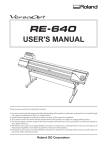
To ensure personal safety and proper maintenance, please read this
section and the caution statements on the unit (refer to the figure
below).
[Location of the Caution Statements]
If the unit begins to emit smoke, smells like something is burning,
or makes strange noises, disconnect all power connections
immediately and contact your dealer for advice.
Attempting to use a malfunctioning unit may result in fire, electric
shock, or equipment damage.
Do not open the cabinet or modify the unit.
Opening the cabinet or modifying the unit may result in fire,
electric shock, or burn.
Refer all servicing to qualified service personnel.
Do not attempt to service this product yourself as opening or
removing covers may result in fire, electric shock, or equipment
damage.
Keep small objects or liquids away from the unit.
Small objects accidentally falling through the ventilation slots into
the cabinet or spillage into the cabinet may result in fire, electric
shock, or equipment damage.
If an object or liquid falls/spills into the cabinet, unplug the unit
immediately. Have the unit checked by a qualified service engineer
before using it again.
Place the unit at the strong and stable place.
A unit placed on an inadequate surface may fall and result in injury
or equipment damage.
If the unit falls, disconnect the power immediately and ask your
dealer for advice. Do not continue using a damaged unit. Using a
damaged unit may result in fire or electric shock.
Use the unit in an appropriate location..
Not doing so may result in fire, electric shock, or equipment
damage.
●
●
●
●
●
Do not place outdoors.
Do not place in the transportation system (ship, aircraft,
trains, automobiles, etc.)
Do not place in a dusty or humid environment.
Do not place in a location where the steam comes directly on
the screen.
Do not place near heat generating devices or a humidifier.
To avoid danger of suffocation, keep the plastic packing bags away
from babies and children.
Use the enclosed power cord and connect to the standard power
outlet of your country.
Be sure to remain within the rated voltage of the power cord.
Not doing so may result in fire or electric shock.
To disconnect the power cord, grasp the plug firmly and pull.
Tugging on the cord may damage and result in fire or electric
shock.
The equipment must be connected to a grounded main outlet.
Not doing so may result in fire or electric shock.
Use the correct voltage.
* The unit is designed for use with a specific voltage only.
Connection to another voltage than specified in this User's Manual
may cause fire, electric shock, or equipment damage.
* Do not overload your power circuit, as this may result in fire or
electric shock.
Handle the power cord with care.
* Do not place the cord underneath the unit or other heavy objects.
* Do not pull on or tie the cord.
If the power cord becomes damaged, stop using it. Use of a
damaged cord may result in fire or electric shock.
Never touch the plug and power cord if it begins to thunder.
Touching them may result in electric shock.
When attaching an arm stand, please refer to the user’s manual of
the arm stand and install the unit securely.
Not doing so may cause the unit to become unattached, which may
result in injury or equipment damage. When the unit is dropped,
please ask your dealer for advice. Do not continue using a damaged
unit. Using a damaged unit may result in fire or electric shock.
When reattaching the tilt stand, please use the same screws and
tighten them securely.
Do not touch a damaged LCD panel directly with bare hands.
The liquid crystal that may leak from the panel is poisonous if it
enters the eyes or mouth.
If any part of the skin or body comes in direct contact with the
panel, please wash thoroughly. If some physical symptoms result,
please consult your doctor.
Follow local regulation or laws for safe disposal.
The backlight of the LCD panel contains mercury.
Handle with care when carrying the unit.
Disconnect the power cord and cables when moving the unit.
Moving the unit with the cord attached is dangerous. It may result
in injury.
When handling the unit, grip the bottom of the unit firmly with
both hands ensuring the panel faces outward before lifting.
Dropping the unit may result in injury or equipment damage.
Do not block the ventilation slots on the cabinet.
* Do not place any objects on the ventilation slots.
* Do not install the unit in a closed space.
* Do not use the unit laid down or upside down.
Blocking the ventilation slots prevents proper airflow and may
result in fire, electric shock, or equipment damage.
Do not touch the plug with wet hands.
Doing so may result in electrical shock.
Use an easily accessible power outlet.
This will ensure that you can disconnect the power quickly in case
of a problem.
Periodically clean the area around the plug.
Dust, water, or oil on the plug may result in fire.
Unplug the unit before cleaning it.
Cleaning the unit while it is plugged into a power outlet may result
in electric shock.
In order to suppress the luminosity change by long-term use and to
maintain the stable luminosity, use of a monitor in lower brightness
is recommended.
The LCD panel is manufactured using high-precision technology.
However, missing pixels or lit pixels may appear on the LCD panel,
this is not malfunction.
Percentage of effective pixels:99.9994%or higher.
The backlight of the LCD panel has a fixed life span. When the
screen becomes dark or begins to flicker, please contact your
dealer.
Do not press on the panel or edge of the frame strongly, as this
may result in damage to the screen. There will be prints left on the
screen if the pressed image is dark or black. If pressure is
repeatedly applied to the screen, it may deteriorate or damage your
LCD panel. Leave the screen white to decrease the prints.
Do not scratch or press on the panel with any sharp objects, such
as a pencil or pen as this may result in damage to the panel. Do not
attempt to brush with tissues as this may scratch the LCD panel.
When the screen image is changed after displaying the same image
for extended periods of time, an afterimage may appear. Use the
screen saver or timer to avoid displaying the same image for
extended periods of time.
When the monitor is cold and brought into a room or the room
temperature goes up quickly, dew condensation may occur inside
and outside the monitor. In that case, do not turn the monitor on
and wait until dew condensation disappears, otherwise it may cause
some damages to it.
Thank you very much for choosing an EIZO Color Monitor.
●
●
●
●
●
●
●
●
The exclusive use calibration software calibrates the monitor
characteristics and generate colorprofile.
Dual inputs compliant
DVI Digital input (TMDS) compliant.
ADC (Apple Display Connector) inputs compliant.
[Horizontal scanning frequency]
Analog: 31 - 94 kHz
Digital: 31 - 76 kHz
[Vertical scanning frequency]
Analog: 49 - 86 Hz Vertical (1600 x 1200: 49 - 76 Hz, 1920 x 1200:
49 - 61 Hz)
Digital: 59 - 61 Hz (VGA text: 69 - 71 Hz))
[Resolution] 1920 dots x 1200 lines
Support to sRGB standard
The height adjustable stand incorporated
Attaching the "Adjustment Certificate" to describe the grayscale and
uniformity characteristics of the monitor individually.
Please contact your local dealer for assistance if any of the listed items are
missing or damaged.
* LCD Monitor
* Power Cord
* Analog Signal Cable (FD-C16)
* Digital Signal Cable (FD-C39)
* EIZO USB Cable (MD-C93)
* EIZO LCD Utility Disk
* User's Manual (in the CD-ROM)
* Calibration software
"ColorNavigator" (in the CD-ROM)
* Setup Guide
* ColorNavigator Quick Reference
* LIMITED WARRANTY
* Adjustment Certificate
* Cleaning kit "ScreenCleaner"
* Hood
* Please retain the packing materials for future transference.
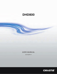
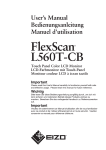
Front
(1)
(2)
(3)
(4)
(5)
(6)
(7)
(8)
ScreenManager®
Mode Switch
Auto Adjustment Switch
Enter Switch
Directing Switch (Left, Down, Up, Right)
Input Signal Selection Switch
Power Switch
Indicator lamp*1
Name
The monitor status when each lamp on
Custom mode of FineContrast Mode
Custom
sRGB mode of FineContrast Mode
sRGB
Left Side
EMU
EMU mode of FineContrast Mode
CAL
CAL mode of FineContrast Mode
Notify that the monitor needs to be recalibrated in
CAL mode or EMU mode.
Adj. Lock The monitor functions are locked.
Signal 1
Input signal from SIGNAL 1 is displayed.
Right Side Signal 2
Input signal from SIGNAL 2 is displayed.
ON
Operation
Power Save Power saving
*1 The brightness of indicator lamps can be changed and turned off, when
the screen is displayed (Operation mode). See "Indicator setting".
Cal. Alert
The power status of the monitor when each lamp on
Indicator Lamp
Power status of the monitor
ON
Power Save
Light
Off
Operation
Off
Light
Power Saving
Off
Off
Power off
* The unit is designed to be operated with your bare fingers. If you touch
the control panel with your gloved fingers or with something left on the
control panel, it may not work.
* If there are waterdrops or dew condensation on the control panel, or
operating with wet fingers, it may not work properly. In that case, be
sure to dry or wipe it up before use.
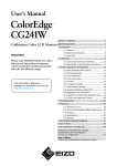
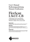
Rear
(9) USB Port (2 Downstream)
(10) USB Port (1 Upstream)
(11) Height Adjustable Stand (Detachable)*2
(12) Security Lock Slot*3
(13) DVI-I Input Connector (SIGNAL 1, SIGNAL2)
(14) Power Connector
*2 The LCD monitor can be used with an optional arm stand by removing
the stand. (See "2-6. How to remove the Tilt Stand").
*3 Allows for connection of a security cable. This lock supports
Kensington's MicroSaver security system.
Before connecting your monitor to the PC, change the display screen settings
(resolution and frequency) in accordance with the charts below.
* When your computer and display support VESA DDC, the suitable
resolution and the refresh rate are set by just plugging your display into
the computer without any manual settings.
Analog Input
Resolution Frequency Dot Clock
640 x 480
60 Hz
640 x 480
67 Hz
640 x 480
~ 85 Hz
720 x 400
70 Hz
800 x 600
~ 85 Hz
832 x 624
75 Hz
1024 x 768 ~ 85 Hz
1152 x 864
75 Hz
1152 x 870
75 Hz
1280 x 960
75 Hz
1280 x 960
60 Hz
202.5 MHz
1280
~85 Hz
(Max.)
x1024
1600 x
~75 Hz
1200
1680 x
60 Hz
1050
1680 x
60 Hz
1050
1920 x
60 Hz
1200
1920 x
60 Hz
1200
Remarks
VGA
Apple Macintosh
VESA
VGA TEXT
VESA
Apple Macintosh
VESA
VESA
Apple Macintosh
Apple Macintosh
VESA
VESA
VESA
VESA CVT
VESA CVT RB (Reduced Blanking)
VESA CVT
VESA CVT RB (Reduced Blanking)
* Some resolution modes may require screen adjustment.
Digital Input
The monitor supports the following resolutions only.
Resolution Frequency Dot Clock
Remarks
640 x 480
60 Hz
VGA
720 x 400
70 Hz
VGA TEXT
800 x 600
60 Hz
VESA
1024 x 768
60 Hz
VESA
1280 x 960
60 Hz
VESA
1280 x
60 Hz
VESA
1024
162 MHz
1600 x
60 Hz
(Max.) VESA
1200
1680 x
60 Hz
VESA CVT
1050
1680 x
60 Hz
VESA CVT RB (Reduced Blanking)
1050
1920 x
60 Hz
VESA CVT RB (Reduced Blanking)
1200
* Be sure that the power switches of both the PC and the monitor are OFF.
1.Open the cable cover and plug the signal cable into the connector at the
rear of the monitor and the other end of the cable into the video
connector on the PC.
After connecting, secure the connection with the screw-in fasteners.
Analog Input
Signal Cable
Signal Cable (FD-C16
enclosed)
Connector
Video Output
Connector / D-Sub
mini 15 pin
Input Connector
(monitor) / DVI
PC
Standard graphics card
Power Macintosh G3
(Blue & White)
Power Mac G4 (VGA)
Signal Cable (FD-C16
enclosed) +Adapter*
Video Output
Connector / D-Sub
15 pin
Input Connector
(monitor) / DVI
Macintosh
*Macintosh Adapter (Optional)
Digital Input
Signal Cable
Signal Cable (FD-C39
enclosed)
Connector
Video Output
Connector / DVI
Input Connector
(monitor) / DVI
PC
Digital graphics card
Power Mac G4 / G5 (DVI)
2.Plug the power cord into the power connector on the rear of the
monitor.
3.Close the cable cover and lead the power cord and signal cable into the
cable holder at rear of the monitor.
* The cables are recommended to lead with slight sag for the smooth
motion of the stand.
* It's recommended to put away the signal cables into the left cable holder,
and the USB cable and power cord into the right cable holder.
4.Plug the other end of the power cord into a power outlet.
WARNING
Use the enclosed power cord and connect to the standard
power outlet of your country.
Be sure to remain within the rated voltage of the power
cord.
Not doing so may result in fire or electric shock.
The equipment must be connected to a grounded main
outlet.
Not doing so may result in fire or electric shock.
5.Turn on the monitor's main power and then switch on the PC's power.
The indicator lamp, "ON", will light up.
If an image does not appear, refer to the "6. TROUBLESHOOTING" for advice.
Whenever finished, turn off the PC and the monitor.
* When turning on the monitor, the kid of the input signal (Signal1 or 2/
Analog or Digital) is displayed for a few seconds on the right top corner
of the screen.
* Adjust brightness of the screen depending on the brightness of your
environment.
* Be sure to take adequate rests. A 10-minute rest period each hour is
suggested.
When connecting a Power Mac G4 / G5 through ADC (Apple Display
Connector), change the input signal settings of monitor in advance to turn on
the Power Mac.
* Be sure that the power switches of both the PC and the monitor are OFF.
1.Open the cable cover and plug the signal cable into the connector at the
rear of the monitor and the other end of the cable into the video
connector on the PC.
After connecting, secure the connection with the screw-in fasteners.
To input the Signal through ADC
Signal Cable
Signal Cable (FD-C39
enclosed) +ADC-DVI
display adapter
(commercially available)
Connector
Video Output
Connector / ADC
Input Connector
(monitor) / DVI
PC
Power Mac G4 / G5(ADC)
* ADC-DVI display adapter is required if the monitor connects to Power
Mac G4 / G5. The adapter is commercially available.
2.Plug the power cord into the power connector on the rear of the
monitor.
3.Close the cable cover and lead the power cord and signal cable into the
cable holder at rear of the monitor.
* The cables are recommended to lead with slight sag for the smooth
motion of the stand.
* It's recommended to put away the signal cables into the left cable
holder, and the USB cable and power cord into the right cable holder.
4.Plug the other end of the power cord into a power outlet.
WARNING
Use the enclosed power cord and connect to the standard
power outlet of your country.
Be sure to remain within the rated voltage of the power
cord.
Not doing so may result in fire or electric shock.
The equipment must be connected to a grounded main
outlet.
Not doing so may result in fire or electric shock.
5.Touch the power switch while touching the Input Signal Selection
switch.
The Input Selection menu is appeared on the screen.
* The unit is designed to be operated with your bare fingers. If you touch
the control panel with your gloved fingers or with something left on the
control panel, it may not work.
* If there are waterdrops or dew condensation on the control panel, or
operating with wet fingers, it may not work properly. In that case, be
sure to dry or wipe it up before use.
6.Change SIGNAL 1 (DVI-I Connector) in the Input Selection menu to
"ADC".
Touch the Enter switch to complete the setting and the menu closes.
7.Switch on the PC's power.
If an image does not appear, refer to the "6. TROUBLESHOOTING" for advice.
Whenever finished, turn off the PC and the monitor.
* When turning on the monitor, the kid of the input signal (Signal1 or 2/
Analog or Digital) is displayed for a few seconds on the right top corner
of the screen.
* Adjust brightness of the screen depending on the brightness of your
environment.
* Be sure to take adequate rests. A 10-minute rest period each hour is
suggested.
* When changing the signal connector except ADC, open the Input
Selection menu again and change the setting to "Standard".
* To <Reset> the settings in the <Others> menu through ScreenManager,
the settings of Input Selection will revert to the default setting.
Two PCs can be connected to the monitor through DVI-I connector and D-sub
mini 15 pin connector on the back of the monitor.
(EX.1) Digital ADC
(EX.2) Digital ADC
(EX.3) Digital ADC
PC 1
Signal Cable (FDC39 enclosed)
+ADC-DVI display
adapter
(commercially
available)
PC 2
Signal Cable
DD200 [FD-C39]
(Optional)
DVI
Signal Cable (FDC39 enclosed)
+ADC-DVI display
adapter
(commercially
available)
Signal Cable (FDC16 enclosed)
Signal Cable (FDC39 enclosed)
+ADC-DVI display
adapter
(commercially
available)
Signal Cable (FDC16 enclosed) +
Adapter*
Digital
D-Sub
mini
Analog
15 pin
D-Sub
Analog
15 pin
Signal Cable (FDC39 enclosed)
Signal Cable FDC16 enclosed)
Signal Cable (FDC39 enclosed)
Signal Cable (FDC16 enclosed)+
Adapter*
(EX.4) Digital DVI
(EX.5) Digital DVI
D-Sub
(EX.6) Analog mini
15 pin
Signal Cable (FDC16 enclosed)
Signal Cable (FDC16 enclosed)
+Adapter*
D-Sub
mini
Analog
15 pin
D-Sub
Analog
15 pin
D-Sub
Analog
15 pin
*Macintosh Adapter (Optional)
Selecting the Active Input
The Input Signal Selection switch on the control panel can be used to select
either SIGNAL 1 or SIGNAL 2 as the active input at any time. Every time the
switch is touched, the input changes. When switching the signal, the kind of
the input signal (Signal 1 or 2/ Analog or Digital) is displayed for a few
seconds on the right top corner of the screen.
The Priority Input Signal
This function is used to select which PC will have priority to control the
monitor when utilizing two PCs. The monitor constantly checks the input
signals and switches automatically in accordance with the "Input Priority"
setting (see table below). Once a priority is set, whenever a change of signal is
detected at the selected input, the monitor will switch the input to that signal.
In this case of only one signal being present at either input, the monitor
automatically detects and displays that signal.
Priority
Settings
1
(SIGNAL1)
Performance
If signals from both inputs are present, the monitor gives
preference of Signal 1 in the following cases.
●
●
2
(SIGNAL2)
If signals from both inputs are present, the monitor gives
preference to Signal 2 in the following cases.
●
●
Manual
When the power of the monitor is turned ON.
When the signal input to Signal 1 is changed even if
active input was Signal 2.
When the power of the monitor is turned ON.
When the signal input to Signal 2 is changed even if
active input was Signal 1.
The monitor will not detect signals automatically in this
mode. Select the active input by pressing the input signal
selection button on the monitor's control panel.
* When "1" or "2" is selected, the power saving mode of the monitor
activates only if both PCs are in power saving mode.
The Hood can reduce light reflection for on screen color consistency.
Setup Procedure
1.Attach the top cover to either the left cover or right cover before
attaching to the monitor.
* Please attach the top cover so that the visor is in back. If the visor is in
front, light will seep in through the back.
2.Attach the left cover and right cover to the monitor.
(1) Firmly attach the left cover and right cover to the monitor from beneath.
(2) Make sure that the rubber cushions are firmly positioned against the
side of the monitor.
(3) Slide the top cover to close.
The LCD monitor can be used with an arm by removing the tilt stand and
attaching the arm or stand to the LCD monitor.
* If you will use the arm or stand of other manufacturers, confirm the
followings to the manufacturers before selecting.
●
●
●
Hole spacing on the arm mounting: 100 mm x 100 mm (VESA
compliant)
Supportable Weight: Total weight of the monitor (without stand)
and attaching equipment such as a cable
TÜV/GS approved arm or stand
* Please connect cables after attaching an arm stand.
Setup Procedure
1.Lay the LCD monitor down. Do not scratch the panel.
2.Remove the tilt stand by loosening the screws. (4 pcs of M4 x 14)
3.Attach an arm stand to the LCD monitor securely.
ScreenManager allows you to adjust screen performance though the main
menu and select a FineContrast mode easily.
* Main Menu and FineContrast menu cannot be activated at the same time.
1.Entering the ScreenManager
Touch the Enter switch once to display the main menu of the ScreenManager.
2.Making Adjustments and Settings
(1) Select the desired sub menu icon using the Directing switch and touch
the Enter switch. The sub menu appears.
(2) Use the Directing switches to select the desired setting icon and touch
the Enter switch. The setting menu appears.
(3) Use the Directing switches to make all required adjustments and touch
the Enter switch to save the settings.
3.Exiting the ScreenManager
(1) To return to the main menu, select the <Return> icon or touch the Down
switch twice, followed by the Enter switch.
(2) To exit the ScreenManager, select <Exit> icon or touch the Down switch
twice, followed by the Enter switch.
* Double clicking the Enter switch at any time also exits the
ScreenManager menu.
FineContrast menu
Touching the Mode switch allows you to select the best suited mode for
screen display from 4 FineContrast modes; Custom, sRGB, EMU and CAL. To
exit the menu, press the Enter switch.
The following table shows all the ScreenManager's adjustment and setting
menus.
"*" indicates adjustments of analog input only and "**" indicates digital input
only.
Main menu
Screen
Sub menu
Clock
Phase
Position
Resolution
Range Adjustment
Smoothing
Signal Filter
Color(Custom) Brightness
*1
Temperature
Gamma
Saturation
Hue
Gain
*
*
*
*
*
Reference
4-1. Screen Adjustment
*
4-3. Color Adjustment
6 Colors
Reset
PowerManager DVI DMPM
VESA DPMS
Others
Screen Size
Border Intensity
Input Priority
Off Timer
Beep
Menu
Settings
Menu Size
Menu
Position
Menu Off
Timer
Translucent
Indicator
Reset
Information
Language
Information
** 4-4. Power-save Setup
*
4-2.Displaying a low resolutions
Select the priority input signal.
Set the monitor's off timer to
on or off.
Set the monitor's beeper to on
or off.
Change the size of the menu.
Adjust the menu position.
Set the menu displaying time.
Set the transparency of the
background.
Adjust the brightness of the
indicator lamps (see "Indicator
setting").
Return to the factory default
settings.
Review the ScreenManager's
settings, model name, serial
number and usage time.*2
Select the ScreenManager's
language.
English, German,
French, Spanish, Italian,
Swedish, Chinese
(Simplified), Chinese
(Traditional) and
Japanese
*1 The adjustable functions on the <Color> menu depend on the selected
FineContrast mode. The above table shows the sub menus when the
"Custom" mode is selected (see "4-3. Color Adjustment").
*2 Due to the inspection on the factory, the usage time may not "0 hour" at
shipping.
This function allows you to select the best suited mode for screen display.
To select the Mode
Touching the Mode switch allows you to select the best suited mode for
screen display from 4 FineContrast modes; Custom, sRGB, EMU and CAL.
Exit
Touch the Enter switch to exit the menu.
FineContrast Mode
Selectable FineContrast modes are as follows.
Custom
sRGB
To adjust the color settings according to your preference.
To display the screen images based on those original colors
(ex. over the Internet).
EMU*1
The mode only for calibration software
CAL*1
*1 When calibrating with provided software, these modes automatically
will be switched.
Color Adjustment of the Mode Settings
<Brightness>, <Temperature> and <Gamma> settings can be adjusted on the
FineContrast menu. Select the desired function icon with the Up/Down
Directing switches and adjust with the Left/Right Directing switches. (Setting
(s) of <Brightness>, <Temperature> and/or <Gamma> is defined as standard
default in some modes.)
Detailed Adjustments
The detailed color settings of each mode can be adjusted by using the <Color>
menu of the ScreenManager.
* "EMU"mode and "CAL" mode can be adjusted only by Calibration
Software "ColorNavigator".
Adjustment Lock
Use the "Adjustment Lock" function to prevent any accidental changes.
●
Locked function
●
●
●
Unlocked
function
●
●
Settings in the ScreenManager
Auto Adjustment Switch
Selecting of the FineContrast mode by the Mode
switch.
Adjustments of the FineContrast mode by the
directing switches
Input Signal Selection Switch
Turning the power on and off by the Power
button
[To lock]
Turn off the monitor's power by touching the power switch. And then touch
the power switch while touching the Auto Adjustment switch.
[To unlock]
Turn off the monitor's power by touching the power switch. And then touch
the power switch while touching the Auto Adjustment switch once again.
Off Timer
The off timer function causes the monitor to automatically enter a power off
state after a predetermined amount of time has lapsed. This function was
created to reduce afterimage characteristics that are particular to LCD
monitors when the monitor screen is left on for a long period without use.
[Procedure]
(1) Select <Off Timer> in the ScreenManager <Others> menu.
(2) Select "Enable" and touch the Right and Left switches to adjust the "On
Period" (1 to 23 hours).
[Off Timer System]
Indicator lamp
ON
Power Save
Operation
Light
Off
On period (1H-23H)
Power saving
Off
Light
Operation
Flashing light
Off
Last 15 min. in "On
*1
period"
Power saving
Off
Light
"On period" expired
Power off
Off
Off
*1 Advance notice will be given 15 minutes before the monitor
automatically enters the "Power Off" mode. To delay entering the
"Power Off" mode, touch the power switch during the advance notice
period. The monitor will continue to operate for an additional 90
minutes.
PC
Monitor
[Power Resumption Procedure]
Touch the power switch to return a normal screen.
Indicator setting
The brightness of indicator lamps can be changed and turned off, when the
screen is displayed (Operation mode).
[Procedure]
(1) Select <Indicator> in the ScreenManager <Others> menu.
(2) If you desire to turn off the lamps, select "Off".
The following lamp are turned off.
●
●
●
●
Custom / sRGB / EMU / CAL
Adj. Lock
Signal1 / Signal2
ON
If you desire to change the brightness of the lamps, select "High" ,
"Medium" or "Low". (Default setting is "Medium")
EIZO Logo Appearing Function
When turning on the monitor, the EIZO logo is displayed for a while. If you
desire to display or undisplay this logo, use this function. (Default is logo
appearing.)
[To undisplay]
Turn off the monitor once, then touch the power switch while touching the
Enter switch, and this logo is not displayed.
[To display]
Turn off the monitor once, then touch the power switch while touching the
Enter switch, and this logo is displayed again.
The monitor displays the digital input image correctly based on its pre-setting
data.
Analog Input
Screen adjustments for the LCD monitor should be used in suppressing screen
flickering and also for adjusting the screen to its proper position. There is only
one correct position for each display mode. It is also recommended to use the
ScreenManager function when first installing the display or whenever
changing the system.
* Allow the LCD monitor to stabilize for at least 30 minutes before making
image adjustments.
Adjustment Procedure
1.Touch the Auto Adjustment Switch on the control panel.
The message appears and remains on the screen for 5 seconds. While the
message is on the screen, touch the Auto Adjustment switch again to
automatically adjust the clock, phase, screen position and resolution. If you do
not wish to do adjust the screen, do not touch the Auto Adjustment switch
again.
* The Auto Adjustment function is intended for use on the Macintosh and
on AT-compatible PC running Windows. It may not work properly in
either of the following cases. It does not work properly when an image is
displayed only on a part of the screen (command prompt window,for
example) or when a black background (wallpaper, etc.) is in use.
* It cannot work correctly using with some graphics cards.
If the appropriate screen cannot be made by using the Auto Adjustment
switch, adjust the screen through the following procedures. If the
appropriate screen can be made, proceed to step 5.
2.Prepare the display pattern for the analog display adjustment.
Windows
(1) Load the “EIZO LCD Utility Disk” to your PC.
(2) Start the “Screen Adjustment Utility” from the startup menu. If it
cannot be started, open the screen adjustment pattern files.
Other than Windows
Download the "Screen adjustment pattern files" from our site: http://www.
eizo.com.
*
For how to open and use the screen adjustment pattern files, refer to
“Readme.txt”.
3.Perform the auto size adjustment again with the analog screen
adjustment pattern displayed.
(1) Display Pattern 1 in full screen on the monitor using the “Screen
Adjustment Utility” or the screen adjustment pattern files.
(2) Touch the Auto Adjustment Switch on the control panel.
The message appears and remains on the screen for 5 seconds.
(3) While the message is on the screen, touch the Auto Adjustment switch
again to automatically adjust the clock, phase, screen position and
resolution.
4.Adjust by using <Screen> menu in the ScreenManager.
(1) Vertical bars appear on the screen
Use the <Clock> adjustment.
=>
Select the <Clock> and eliminate the vertical bars by using the Right and
Left of the Directing switches.
Do not continuously touch the Directing switches, as the adjustment
value will change quickly and make it difficult to locate the most suitable
adjustment point. If the horizontal flickering, blur or bars appear,
proceed to <Phase> adjustment as follows.
(2) Horizontal bars appear on the screen.
Use the <Phase> adjustment.
=>
Select the <Phase> and eliminate the horizontal flickering, blurring or
bars by using the Right and Left switches.
* Horizontal bars may not completely disappear from the screen
depending on the PC.
(3) The screen position is incorrect.
Use the <Position> adjustment.
=>
The correct displayed position of the monitor is decided because the
number and the position of the pixels are fixed. The <Position>
adjustment moves the image to the correct position.
Select <Position> and adjust the position by using the Up, Down, Right
and Left switches.
If vertical bars of distortion appear after finishing the <Position>
adjustment, return to <Clock> adjustment and repeat the previously
explained adjustment procedure. ("Clock" => "Phase" => "Position").
(4) Screen image is smaller or larger than the actual screen images.
Use the <Resolution> adjustment.
=>
Adjustment is needed when the input signal resolution and the
resolution now being displayed are different.
Select <Resolution> and confirm if the resolution now being displayed is
the same as the input resolution. If it is not, adjust the vertical resolution
using the Up and Down switches and adjust the horizontal resolution
using the Right and Left switches.
5.Adjust the output signal range (Dynamic Range) of the signal.
=>
Use the <Range Adjustment> of <Screen> menu.
This controls the level of output signal range to display the whole color
gradation (256 colors).
[Procedure]
(1) Affichez le motif 2 en plein écran sur le moniteur à l’aide de l’ «
Utilitaire de réglage de l’écran » ou du fichier de motifs de réglage de
l’écran.
(2) Sélectionnez <Niveau> sur le menu <Écran> et appuyez sur l
´interrupteur de Adjustment Auto.
Le message « Vos réglages seront perdus sivous appuyez sur AUTO. »
s’ affiche.
(3) Appuyez sur l´interrupteur de Adjustment Auto pendant que le
message est affiché.
La palette de couleurs est réglée automatiquement..
(4) Fermez le motif 2. Si vous utilisez l’« Utilitaire de réglage de l’écran »,
fermez le programme.
The lower resolutions are enlarged to full screen automatically. Using the
<Screen Size> function in the <Others> menu enables to change the screen size.
1.Enlarge the screen size when displaying a low resolution.
Select the <Screen Size>.
=>
Select the <Screen Size> in the others menu and select the screen size by using
the Up and Down buttons.
Menu
Full
Enlarged
Normal
Function
Displays the picture on the screen in full, irrespective of
the picture's resolution. Since the vertical resolution
and the horizontal resolution are enlarged at different
rates, some image may appear distorted.
Displays the picture on the screen in full, irrespective of
the picture's resolution. Since the vertical resolution
and horizontal resolution are enlarged at the same
rates, some horizontal or vertical image may disappear.
Displays the picture at the actual screen resolution.
Example: Displaying 1280 x 1024
2.Smooth the blurred texts of the enlarged screen.
=>
Switch the <Smoothing> setting.
When a low-resolution image is displayed in the “Full” or “Enlarged”
mode, the characters or lines of the displayed image may be blurred.
Select the suitable level 1-5 (Soft-Sharp).
Select <Smoothing> in the <Screen> menu and adjust by using the Right and
Left switches.
* <Smoothing> is disabled when the screen is displayed in the following
resolutions.
●
●
●
1920 x 1200
The image size is doubled both in horizontally and vertically to (i.
e. 1600 x 1200 enlarged from 800 x 600) provide clear focus
which does not require this function.
"Normal" is selected in <Screen Size>.
3.Set the brightness of the black area surrounding the displayed image.
=> Set the <Border Intensity>.
In the "Enlarge" mode or "Full Screen" mode, the outer area (border) is usually
black.
Select <Border Intensity> in the <Others> menu and adjust by using the Right
and Left switches.
Color settings of each FineContrast mode can be adjusted and saved by using
the <Color> menu of the ScreenManager.
In the analog input, perform the <Range Adjustment> before making the
color adjustments.
During color adjustments, the FineContrast mode cannot be changed.
Select the mode in advance by using the Mode switch.
Adjustment Items
The adjustable items and displayed icons on the <Color> menu depend on the
selected FineContrast mode.
Icons
Functions
"*": Settable/Adjustable
FineContrast Modes
Custom sRGB EMU CAL
Brightness**
*
*
-
-
Temperature**
*
-
-
-
*
-
-
-
Saturation
*
-
-
-
Hue
*
-
-
-
*
-
-
-
*
-
-
-
Gamma**
Gain
6 colors
Reset
*
**These settings can be also adjusted on the FineContrast menu.
* Allow the LCD monitor to stabilize for at least 30 minutes before making
image adjustments. (Allow the monitor to warm Up for at least 30
minutes before making adjustments.)
* Performing the <Reset> of the <Color> menu returns the color settings
of the selected mode to the default settings.
* The values shown in percentages represent the current level within the
specific adjustment. They are available only as a reference tool. (To
create a uniform white or black screen, the percentages for each will
probably not be the same.)
Adjustment Contents
Menu
Brightness
Function Descriptions
Adjustable Range
To set the brightness of the 0 ~ 100%
screen
Temperature To set the color
temperature
4000 ~ 10000 K
in 500 K increments (including
9300 K). Default setting is
5000K
* The values shown in the Kelvin are available only as a
Gamma
reference tool.
* Adjusting the <Gain> turns the <Temperature>
adjustment "OFF".
* Setting the temperature under 4000 K or over 10000
K invalidates the color temperature setting. (The color
temperature's setting turns "OFF".)
To set the gamma value
1.8 ~ 2.6 (in 0.2 increments)
* If setting the gamma value, the using the monitor in
Saturation
the digital signal input is recommended.
If using the monitor in the analog input signal, set the
gamma value from 1.8 to 2.2.
To change the saturation
-100 ~ 100
Setting the minimum level (100) turns the image to the
monochrome.
* The <Saturation> adjustment may cause undisplayable
color tone.
Hue
To change the flesh color,
etc.
-100 ~ 100
* The <Hue> adjustment may cause undisplayable color
Gain
tone.
To change each color (red,
green and blue)
10 ~ 100%
By adjusting the red, green and
blue color tones for each mode,
custom colors can be defined.
Display a white or gray
background image and adjust
the <Gain>.
* The values shown in the percentage are available only
6 colors
Reset
as a reference tool.
* Setting the <Temperature> invalidates the <Gain>
adjustment. <Gain> setting returns to the default
setting.
To adjust <Saturation> and Hue: -100 ~ 100
<Hue> in each color (Red, Saturation: -100 ~ 100
Yellow, Green, Cyan, Blue
and Magenta)
To return the color settings Select the <Reset>.
of the selected mode to the
default settings
The <PowerManager> menu in the ScreenManager enables to set the powersave setup.
* Do your part to conserve energy, turn off the monitor when you are
finished using it. Disconnecting the monitor from the power supply is
recommended to save energy completely.
* Even if the monitor is in a power saving mode, USB compliant devices
function when they are connected to the monitor's USB (both the
Upstream and the Downstream ports). Therefore, power consumption of
the monitor will change according to the connected devices even if the
monitor is in a power saving mode.
Analog Input
This monitor complies with the "VESA DPMS" standard.
To use the PC's Power Saving System (VESA DPMS).
[Procedure]
(1) Set the PC's power saving settings.
(2) Select "VESA DPMS" in the <PowerManager> menu.
[Power saving system]
PC
Operation
STAND-BY
Power saving SUSPEND
OFF
Monitor
Operation
Power saving
Indicator lamp
ON
Power Save
Light
Off
Off
[Power Resumption Procedure]
Operate the mouse or keyboard to return to a normal screen.
Light
Digital Input
This monitor complies with the "DVI DMPM".
[Procedure]
(1) Set the PC's power saving settings.
(2) Select "DVI DMPM" from the <PowerManager> menu.
[Power saving system]
PC
Operation
STAND-BY
Power saving SUSPEND
OFF
Monitor
Operation
Power saving
Indicator lamp
ON
Power Save
Light
Off
Off
[Power Resumption Procedure]
Operate the mouse or keyboard to return to a normal screen .
Light
This monitor provides a hub which supports the USB standard. When
connecting to a USB compliant PC or another hub, the monitor functions as a
hub which the USB compliant peripherals can be easily connected.
Required System Environment
* PC equipped with USB ports or another USB hub connected to the USB
compliant PC
* Windows 98/Me/2000/XP//Mac OS 8.5.1 or later
* EIZO USB Cable (MD-C93, enclosed)
* The USB hub function may not work properly depending on the PC, OS
or peripherals. Please consult the manufacturer of each device about the
USB support.
* Using the USB Rev . 2.0 compatible PC or peripherals is recommended.
* If the monitor is in the power saving mode, or if the monitor is
connected to the power outlet with the monitor turned off, all the
devices connected to the USB ports (upstream and downstream) work.
Therefore, power consumption of the monitor varies with connected
devices even in the power saving mode.
* The followings are procedures for the Windows 98/Me/2000/XP and
Mac OS.
Connecting to the HUB USB
1.Connect the monitor to the PC with the signal cable first, then turn on
the PC.
2.Connect the upstream port of the monitor to the downstream port of
the USB compliant PC or another hub by using the USB cable.
After connecting the USB cable, the USB function can be set up automatically.
3.After setting up, the monitor's USB hub is available for connecting USB
compliant peripherals to the downstream ports of the monitor.
Connecting Examples
If a problem persists even after applying the suggested remedies, contact an
EIZO dealer.
●
●
●
●
No picture problems : See No.1 ~ No.2
Imaging problems : See No.3 ~ No.14
Other problems : See No.15 ~ No.18
USB problems : See No.19 ~ No.20
Problems
1. No picture
Status of Indicator lamp
"ON" is off.
Status of Indicator lamp
"ON" is light.
Status of Indicator lamp
"Power Save" is light.
Points to check with possible solutions
[ ] Check that there is nothing left on the
face of Power switch. Wipe the control
panel, and then touch the Power switch
again with dry finger.
[ ] Check that the power cord is correctly
connected.
If the problem persists, turn off the
monitor power for a few minutes, then
turn it back on and try again.
[ ] Try touching the power switch to turn it
on again.
[ ] Check the Gain setting.
[ ] Switch the signal Input by touching the
input signal selection switch on the front
control panel.
[ ] Try touching a key on the keyboard, or
clicking the mouse.
2. The message below appears.
The message appears when
the signal is not input. (This is
displayed for about 40
seconds).
[]
[]
[]
[]
These messages appear when the signal
is not inputted correctly, even if the
monitor functions properly.
When the image is displayed correctly
after a short time, there is no problem
with the monitor. (Some PCs do not
output the signal soon after powering
on.)
Check that the PC is turned ON.
Check that the signal cable is properly
connected the PC or graphics board.
Switch the signal input by touching the
Input Signal Selection switch on the
control panel.
The signal frequency is out of
range. Error signal frequency
will be displayed in red.
(Example)
[ ] Reboot the PC.
[ ] Use the graphics board's utility software
to change the frequency setting. (Refer to
the manual of the graphics board.)
fD : Dot Clock
(Displayed only when the digital
signal inputs)
fH : Horizontal Frequency
fV : Vertical Frequency
3. Display position is incorrect. [ ] Adjust the image position using the
<Position>.
[ ] If the problem persists, use the graphics
board's utility software to change the
display position if available.
4. Screen image is smaller or
larger than the actual
screen images.
[ ] Adjust the resolution using the
<Resolution>.
5. Vertical bars of distortion
appear.
[ ] Decrease the vertical bars using the
<Clock>.
6. The characters and images
have several vertical bars
on their right side.
[ ] Adjust the characters and images using
the <Signal Filter>.
7. Horizontal bars of
distortion appear.
[ ] Decrease the horizontal bars using the
<Phase>.
8. Letters and lines appear
blurred.
[ ] Adjust the blurred lines using
<Smoothing>.
9. Distortion appears like the
figure below.
[ ] This happens when both composite (XOR) input signal and separate vertical
synchronizing signal are input. Please
select one of the two.
10.The screen is too bright or
too dark.
[ ] Adjust the <Brightness> (The backlight
of the LCD monitor has a fixed life span.
When the screen becomes dark or
begins to flicker, please consult your
dealer.)
[ ] Do you use the screen saver or timer
when displaying the same image for
extended periods of time?
[ ] Afterimages are particular to LCD
monitors. Avoid displaying the same
image for extended periods of time.
[ ] This is due to the characteristics of the
panel itself, and not the LCD product.
11.Afterimages appear.
12.The screen has defective
pixels (e.g. slightly light or
dark).
13.Fingerprints remain on the
screen.
[ ] Leaving the screen white may solve the
problem.
14.The noise appears on the
screen.
[ ] When entering the signals of analog
input, select 1 to 4 in <Signal Filter>
from the <Screen> menu to change the
mode.
15.The <Smoothing> cannot be [ ] <Smoothing> is disabled when the
screen is displayed in the 1920 x 1200.
selected.
[ ] <Smoothing> is disabled when "Normal"
is selected in the <Screen Size> menu.
[ ] The image size is doubled both in
horizontally and vertically to (i.e. 1600 x
1200 enlarged from 800 x 600) provide
clear focus which does not require this
function.
[ ] Check that there is nothing left on the
16.The Main menu of
face of Enter switch. Wipe the control
ScreenManager does not
panel, and then touch the Enter switch
operate.
again with dry finger.
If the problem persists, the adjustment
lock is probably on. To unlock: switch
the LCD monitor off. Then, while
touching the Auto Adjustment switch,
the power on.
17.The Auto adjustment switch [ ] Check that there is nothing left on the
face of Auto Adjustment switch. Wipe
does not operate.
the control panel, and then touch the
Auto Adjustment switch again with dry
finger.
If the problem persists, the adjustment
lock is probably on. To unlock: switch
the LCD monitor off. Then, while
touching the Auto adjustment switch,
switch the power on.
[ ] The Auto sizing function is intended for
use on the Macintosh and on ATcompatible PC running Windows.
It may not work properly in either of the
following cases.
When running an AT-compatible PC on
MS-DOS (Not windows). The background
color for the "wall paper" or "desktop"
pattern is set to black.
18.Frequency does not change [ ] Use the graphics board's utility software
to change the input signal frequency.
after installing "Monitor
information file" in the
attached utility disk on
Windows 98/Me/2000/XP.
19.USB function cannot be
setup.
20.PC is hung up. / The
peripherals connected to
the downstream ports do
not operate.
[ ] Check that the USB cable is correctly
connected.
[ ] Check that the PC and OS are USB
compliant. (For verification of USB
support, consult the manufacturer of
each system.)
[ ] Check the PC's BIOS setting for USB.
( For details, refer to the manual of the
PC.)
[ ] Check that the USB cable is correctly
connected.
[ ] Check the downstream ports by
connecting the peripherals to other
downstream ports. If the problem is
solved by doing this, contact an EIZO
dealer. (For details, refer to the manual
of the PC.)
[ ] Try executing the following method.
●
●
Restarting the PC - Restarting the
PC
Connecting the PC and
peripherals directly
If the problem is solved by doing this,
contact an EIZO dealer.
Periodic cleaning is recommended to keep the monitor looking new and to
prolong its operation lifetime.
* Never use thinner, benzene, alcohol (ethanol, methanol, or isopropyl
alcohol), abrasive cleaners, or other strong solvents, as these may cause
damage to the cabinet or LCD panel.
Cabinet
To remove stains, wipe the cabinet with a soft, lightly moistened cloth using a
mild detergent. Do not spray wax or cleaner directly into the cabinet. (For
details, refer to the manual of the PC.)
LCD Panel
●
●
The LCD surface can be cleaned with a soft cloth, such as cotton or
lens paper.
If necessary, stubborn stains can be removed by using the provided
ScreenCleaner, or moistening part of a cloth with water to enhance its
cleaning power.
56.4 cm (22.2 inch), TFT color LCD panel with AntiLCD Panel
Glare Hard Coating
Viewing Angle: H: 170°, V: 170° (at contrast ratio 1:5)
Dot Pitch
0.249 mm
Horizontal Scan
Analog: 31 - 94 kHz (Automatic)
Frequency
Digital: 31 - 76 kHz
Analog: 49 - 86 Hz (Automatic)
Vertical Scan Frequency (1600 x 1200: 49 - 76 Hz, 1920 x 1200: 49 - 61 Hz)
Digital: 59 Hz - 61Hz, (VGA Text : 69 - 71 Hz)
Resolution
1920 dots x 1200 lines
Dot Clock (Max.)
Analog: 202.5 MHz, Digital: 162 MHz
Display Colors
16 million colors (max.)
478 mm (H) x 299 mm (V) (18.8" (H) x 11.8" (V))
Display Area
(Viewable image size: 564 mm (22.2"))
Power Supply
100-120V/200-240V, 50/60 Hz, 1.0A/0.5A
Min.: 90 W
Max: 100 W (with USB)
Power Consumption
Power Saving Mode : Less than 2 W (for single signal
input without USB)
Power off : Less than 1 W
Recommended
100cd/m2 or less
Brightness
(with color temperature of between 5000K to 6500K)
Input Connector
DVI-I x 2
a) Separate, TTL, Positive/Negative
Analog Input Signal
(Sync)
b) Composite, TTL, Positive/Negative
Analog Input Signal
0.7Vp-p/75 ohms, Positive
(Video)
Input Signal (Digital)
TMDS (Single Link)
Analog : 45 (Preset: 29)
Signal registration
Digital : 10
Plug & Play
VESA DDC 2B / EDID structure 1.3
565 mm (W) x 452.5 - 552.5 mm (H) x 272 mm (D)
Dimensions
(22.2"(W) x 17.8"- 21.8"(H) x 10.7"(D))
Dimensions
574.6mm (W) x 460.6 - 560.6mm (H) x 353.9 mm (D)
(with hood)
(22.6"(W) x 18.1"- 21.1"(H) x 13.9"(D))
Dimensions (without
565 mm (W) x 394.5 mm (H) x 101 mm (D)
stand)
(22.2"(W) x 15.5"(H) x 4"(D))
Weight
14.5 kg (32 lbs.)
Weight
15.5 kg (34.2 lbs.)
(with hood)
Weight
10.4 kg (22.9 lbs.)
(without stand)
Temperature
USB standard
Communication speed
USB ports
Operating: 0 °C - 35 °C (32 °F - 95 ° F)
Storage: -20 °C - 60 °C (-4 °F - 140 ° F)
Humidity 30% to 80% R.H. Non-condensing
USB Specification Revision 2.0
480Mbps(high), 12 Mbps (full), 1.5 Mbps (low)
Upstream port x 1, Downstream port x 2
Default settings
Brightness
Smoothing
Temperature
FineContrast Mode
PowerManager
Screen Size
Input Priority
Off Timer
Indicator
Menu Size
Menu
Settings
Menu Off Timer
Beep
Language
Input Selection
Analog input
60%
Digital input
60%
3
5000K
Custom
VESA DPMS
DVI DMPM
Full
Signal 1
Disable
Medium
Normal
45 seconds
On
English
Standard
Beeper settings
Short beep
Long beep
4 short beeps
2 short beeps
every 15 sec.
ScreenManager item selected.
ScreenManager parameter adjusted to minimum or
maximum limit.
Input Signal Selection switch touched.
Auto Adjustment switch touched.
ScreenManager data-save executed.
Monitor not connected correctly.
PC turned off.
Monitor received unsupported signal frequency.
Monitor is in the advance notice mode of the Off Timer.
The power will be off within fifteen minutes.
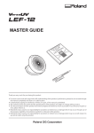
Dimensions
Unit mm (inches)
Pin Assignment
DVI-I Connector
Pin
No.
Signal
4
TMDS Data
2TMDS Data
2+
TMDS Data
2/4 Shield
NC*
5
NC*
1
2
3
6
DDC Clock
(SCL)
Pin
No.
Signal
Pin
No.
Signal
11
TMDS Data
1/3 Shield
21
NC*
12
NC*
22
TMDS Clock
Shield
13
NC*
23
TMDS Clock+
24
TMDS Clock-
C1
Analog Red
C2
Analog Green
14
+5V Power
Ground
(return for
15
+5V, Hsync
and Vsync)
Hot Plug
16
Detect
DDC Data
17 TMDS Data0- C3
Analog Blue
(SDA)
Analog
Analog
18 TMDS Data0+ C4
8
Horizontal Sync
Vertical Sync
TMDS
Analog Ground
TMDS
19
Data0/5
C5 (analog R, G, & B
9
Data1Shield
return)
TMDS Data1
20
NC*
10
+
(NC*: No Connection)
USB Ports (USB Specification Revision 2.0)
7
No.
1
2
3
4
Signal
VCC
-Data
+Data
Ground
Remarks
Cable power
Serial data
Serial data
Cable Ground
Clock
With the analog input signal display, the analog signal is converted to a
digital signal by the LCD circuitry. To convert the signal correctly, the LCD
monitor needs to produce the same number clock pulse as the dot clock of
the graphics system. When the clock pulse is not correctly set, some vertical
bars of distortion are displayed on the screen.
Color Temperature (Temperature)
Color Temperature is a method to measure the white color tone, generally
indicated in degrees Kelvin. At high temperatures the white tone appears
somewhat blue, while at lower temperatures it appears somewhat red.
Computer monitors generally give best performance at high temperature
settings.
5000 K: Slightly reddish white.
6500 K: Warm-white tone, similar to white paper or daylight.
9300 K: Slightly bluish white.
DVI (Digital Visual Interface)
A digital flat panel interface. DVI can transmit digital data from the PC
directly without loss with the signal transition method "TMDS".
There are two kinds of DVI connectors. One is DVI-D connector for digital
signal input only. The other is DVI-I connector for both digital and analog
signal inputs.
DVI DMPM (DVI Digital Monitor Power Management)
The Power management system for the digital interface. The "Monitor ON"
status (operation mode) and the "Active Off" status (power-saving mode) are
indispensable for the DVI-DMPM as the monitor's power mode.
Gain Adjustment
Adjusts each color parameter for red, green and blue. The color of the LCD
monitor is displayed through the color filter of the LCD panel. Red, green and
blue are the three primary colors. The colors on the monitor are displayed by
combining these three colors. The color tone can change by adjusting the
illumination amount passed through each color's filter.
Gamma
Generally, the relationship that the light intensity values of a monitor change
nonlinearly to the input signal level is called "Gamma Characteristic". On the
monitor, low gamma values display the whitish images and high gamma
values display the high contrast images.
Phase
The phase adjustment decides the sampling timing point for converting the
analog input signal to a digital signal. Adjusting the phase after the clock
adjustment will produce a clear screen.
Range Adjustment
The Range Adjustment controls the level of output signal range to display the
whole color gradation.
Resolution
The LCD panel consists of a fixed number of pixel elements which are
illuminated to form the screen image. The EIZO CG221 display panel consists
of 1920 horizontal pixels and 1200 vertical pixels. At a resolution of 1920 x
1200, all pixels are displayed as a full screen.
sRGB (Standard RGB)
"International Standard for Red, Green, and Blue color space" A color space
was defined with the aim of the color matching between applications and
hardware devices, such as monitors, scanners, printers and digital cameras.
As a standard default space, sRGB allows Internet users to closely match
colors.
TMDS (Transition Minimized Differential Signaling)
A signal transition method for the digital interface.
VESA DPMS
(Video Electronics Standards Association - Display Power Management
Signaling)
The acronym VESA stands for "Video Electronics Standards Association", and
DPMS stands for "Display Power Management Signaling". DPMS is a
communication standard that PCs and graphics boards use to implement
power savings on the monitor side.
Preset Timing Chart for Analog input
Timing-Übersichten für Analog Eingang
Synchronisation des Signaux pour Analog numerique
Based on the signal diagram shown below factory presets have been
registered in the monitor's microprocessor.
Der integrierte Mikroprozessor des Monitors unterstützt 30 werkseitige
Standardeinstellungen (siehe hierzu die nachfolgenden Diagramme).
30 signaux ont été enregistrés en usine dans le microprocesseur du moniteur,
conformément au diagramme de synchronisation ci-dessous.
Mode
VGA
640×480
VGA Text
720×400
Macintosh
640×480
Macintosh
832×624
Macintosh
1152×870
Macintosh
1280×960
VESA
640×480
VESA
640×480
VESA
640×480
VESA
800×600
VESA
800×600
VESA
800×600
Dot Clock
MHz
Sync Polarity
H
V
Frequencies
fH: kHz fV: Hz
25.2 MHz
Nega
Nega
31.5
60.0
28.3 MHz
Nega
Posi
31.5
70.1
30.2 MHz
Nega
Nega
35.0
66.7
57.3 MHz
Nega
Nega
49.7
74.6
100.0 MHz
Nega
Nega
68.7
75.1
126.2 MHz
Posi
Posi
74.8
74.8
31.5 MHz
Nega
Nega
37.9
72.8
31.5 MHz
Nega
Nega
37.5
75.0
36.0 MHz
Nega
Nega
43.3
85.0
36.0 MHz
Posi
Posi
35.2
56.3
40.0 MHz
Posi
Posi
37.9
60.3
50.0 MHz
Posi
Posi
48.1
72.2
VESA
800×600
VESA
800×600
VESA
1024×768
VESA
1024×768
VESA
1024×768
VESA
1024×768
VESA
1152×864
VESA
1280×960
VESA
1280×1024
VESA
1280×1024
VESA
1280×1024
VESA
1600×1200
VESA
1600×1200
VESA
1600×1200
VESA
1600×1200
VESA CVT
1680×1050
VESA CVT
1920×1200
VESA CVT RB
1920×1200
49.5 MHz
Posi
Posi
46.9
75. 0
56.3 MHz
Posi
Posi
53.7
85.1
65.0 MHz
Nega
Nega
48.4
60.0
75.0 MHz
Nega
Nega
56.5
70.1
78.8 MHz
Posi
Posi
60.0
75.0
94.5 MHz
Posi
Posi
68.7
85.0
108.0 MHz
Posi
Posi
67.5
75.0
108.0 MHz
Posi
Posi
60.0
60.0
108.0 MHz
Posi
Posi
64.0
60.0
135.0 MHz
Posi
Posi
80.0
75.0
157.5 MHz
Posi
Posi
91.2
85.0
162.0 MHz
Posi
Posi
75.0
60.0
175.0 MHz
Posi
Posi
81.3
65.0
189.0 MHz
Posi
Posi
87.5
70.0
202.5 MHz
Posi
Posi
93.8
75.0
146.3 MHz
Nega
Posi
65.3
60.0
193.3 MHz
Nega
Posi
74.6
60.0
154.0 MHz
Posi
Nega
74.0
60.0
Recycling Information for customers in EU:
All recycling information is placed in the following websites.
Recycling-Information für Kunden in Europa:
Alle Informationen zum Thema Recycling finden Sie auf den folgenden
Websites:
Informations sur le recyclage pour les clients dans l'UE:
Vous trouverez toutes les informations sur le recyclage dans les sites Web
suivants:
Återvinningsinformation för kunder i EU:
All information om återvinning finns på följande webbsidor:
http://www.swico.ch
http://www.eizo.de
http://www.eizo.se
Recycling Information for customers in USA:
All recycling information is placed in the Eizo Nanao Technologies, Inc.'s
website.
http://www.eizo.com