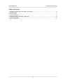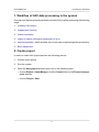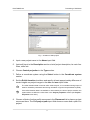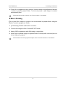
1
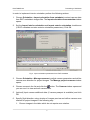
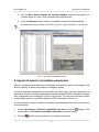
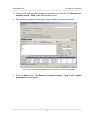
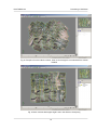
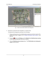
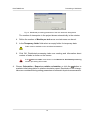
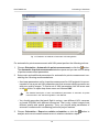
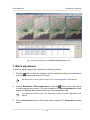
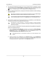
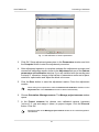
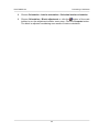
Digital Photogrammetric System
Version 5.3
USER GUIDE
Processing of UAV data
PHOTOMOD 5.3
Processing of UAV data
Table of Contents
1. Workflow of UAV data processing in the system ......................................................................... 3
2. Create project .......................................................................................................................... 3
3. Block forming ........................................................................................................................... 5
4. Interior orientation .................................................................................................................... 6
5. Import of exterior orientation parameters .................................................................................... 8
6. Aerial triangulation .................................................................................................................. 13
7. Block adjustment .................................................................................................................... 18
2
PHOTOMOD 5.3
Processing of UAV data
1. Workflow of UAV data processing in the system
Processing of data acquired by pilotless vehicles (UAV) implies performing the following
steps:
1. Creating UAV project.
2. Images block forming.
3. Interior orientation.
4. Import of exterior orientation parameters (if any).
5. Aerial triangulation, which includes the correct order of preset algorithm processing.
6. Block adjustment.
2. Create project
In order to create UAV project perform the following actions:
1. Choose active profile.
2. Run the system.
3. Open the New project window using one of the following ways:
• choose Project › Open/Manage; click the Create button in the Project management window;
• choose Project › New.
3
PHOTOMOD 5.3
Processing of UAV data
Fig. 1. Creation of UAV project
4. Input a new project name to the Name input field.
5. [optional] Input to the Description section a brief project description, its main features, notes etc.
6. Choose Central projection in the Type section.
7. Define a coordinate system using the Select button in the Coordinate system
section.
8. Set the Relief elevation checkbox and specify at least approximately difference of
terrain heights on project images in the min and max input fields.
The relief elevation data is used to refine a block layout, it is considered during import of
exterior orientation parameters and during calculation of ground sample distance (GSD).
If the relief elevation data is unavailable or inaccurate by the time of project creation, the
system allows to define the value later in the Project properties window (the Project ›
Properties menu item).
9. Choose a folder of active profile resources in the Placement list to place a project
resources there. The Full project path input field shows a name and a path of a
project.
4
PHOTOMOD 5.3
Processing of UAV data
10. Click OK to complete a project creation. Service folders and configuration files are
created in specified project folder. The first strip used to add images is created
automatically then.
See details about project creation in the “Project creation” User Manual.
3. Block forming
Prior to load UAV images to a project it is recommended to prepare them using the
Raster Converter program as follows:
1. [if necessary] Perform radiometric correction.
2. Convert the images to files of inner MS-TIFF format.
3. Apply JPEG compression with 85% quality to output files.
4. Save files of modified images to separate folder of active profile resources (but not
to the folder of a project).
See the Raster Converter program description in the “General information” User Manual.
5
PHOTOMOD 5.3
Processing of UAV data
Fig. 2. Images conversion in the Raster Converter program
Perform the following actions to load images to a project and to form a block:
1. Choose Window › Block editor (for convenient work). The Block editor window
opens.
2. Choose Block › Add images from resources or click the
button in the Block
editor window to start images adding. The Open window opens, allowing to display
all active profile resources.
3. [optional] To filter showing files choose Image in TIFF format in the list rightward
to the Recourses name field.
4. . Choose images files and click the Open button. After that all images are loaded
to the first strip.
See a description of images load, setup and editing of images block in the “Project creation”
User Manual.
4. Interior orientation
Interior orientation operation includes input or import of camera parameters, specifying
of flight direction and angle of camera axes rotation for images of a project.
6
PHOTOMOD 5.3
Processing of UAV data
In order to implement interior orientation perform the following actions:
1. Choose Orientation › Import orientation from metadata to extract camera data
from EXIF-metadata in images files. The Import orientation from metadata window
opens.
2. Set the Import interior orientation and Import exterior orientation checkboxes
(if EXIF-metadata contains exterior orientation parameters). Click OK.
Fig. 3. Import orientation parameters from EXIF-metadata
3. Choose Orientation › Manage cameras to adjust camera parameters and define
camera axes direction for project images. The Manage project cameras window
opens.
4. Choose camera in the list and click the
button. The Camera window opens and
you can use it to view and edit camera data.
5. [optional] Input camera additional data (if camera passport is available) and click
OK.
6. Specify flight direction using window of images preview and define camera axes
rotation for project images in the following way:
1. Choose images in the table which do not require axes rotation.
7
PHOTOMOD 5.3
Processing of UAV data
2. Set the Set camera rotation for selected images checkbox and specify a
rotation angle so, that Х axis coincides with flight direction.
3. Click the Execute button. Interior orientation is performed automatically.
See detailed description of interior orientation step in the “Aerial triangulation” User Manual.
Fig. 4. The interior orientation window
5. Import of exterior orientation parameters
Exterior orientation parameters are coordinates of projection centers and 3 angles, that
allow to specify in whole real position of images in space.
If exterior orientation parameters are available for UAV project, you can import them to
the project. Exterior orientation parameters may be included to EXIF-metadata of images
files or separately as a catalogue in a file of text format. You can find more about import
of preliminary exterior orientation data from EXIF-metadata in Section 4.
In order to perform import of exterior orientation data catalogue from a file of text format,
do the following:
1. Choose Orientation › Exterior orientation data list or click the
button of the
main toolbar. The Exterior orientation parameters window opens.
2. Click the
button to import exterior orientation parameters.
8
PHOTOMOD 5.3
Processing of UAV data
3. Choose a file with exterior orientation parameters and click OK. The Exterior orientation import – Step 1 of 2: File window opens.
4. Setup a string template according to a type of data in columns of text file.
Fig. 5. Setup a file string template for import of exterior orientation parameters
5. Click the Next button. The Exterior orientation import – Step 2 of 2: Import
parameters window opens.
9
PHOTOMOD 5.3
Processing of UAV data
Fig. 6. Import options of exterior orientation parameters
6. Define import parameters: units of angles measurements, sign character of angles
in case of their incorrect defining by automatic pilot, as well as RMS of projection
centers and exterior orientation angles.
See a detailed description of string template setup and import options of exterior orientation
parameters from text format file in the “Aerial triangulation” User Manual.
7. Click the Execute button to close the window and import exterior orientation parameters. Exterior orientation parameters obtained after the import are displayed in
the table of the Exterior orientation parameters window.
8. Click the Apply button in the Exterior orientation parameters window to save
exterior orientation parameters folder in the project.
9. Click OK to close the window and automatic re-build of the block scheme by exterior orientation (to build initial block layout).
10
PHOTOMOD 5.3
Processing of UAV data
Fig. 7. Catalogue of exterior orientation parameters
In order to eliminate blunders in block scheme building by exterior orientation parameters,
perform the following actions:
1. Refine block layout parameters, by performing the following actions:
1. Click the
button of the main toolbar. The Block layout window opens.
2. Choose the By ext. or. mode and click the Apply button.
See a description of block layout creation in the “Aerial triangulation” User Manual.
2. Import exterior orientation parameters from a file of text format once more and refine
import parameters.
3. [optional] If course angle is measured not from central meridian, but from flight direction, perform the following actions:
1. Choose Block › Split into strips › By exterior orientation data. The Split
into strips by exterior orientation window opens.
2. Specify move direction along strips and inside strips. Click OK.
3. Click the
button of the main toolbar. The Exterior orientation parameters
window opens containing the catalogue of exterior orientation parameters.
4. Click the
button to set kappa angle in the direction of trajectory for all or for
selected images. Click OK.
11
PHOTOMOD 5.3
Processing of UAV data
Fig. 8. Example of incorrect block scheme, when a course angle is not measured from central
meridian
Fig. 9. Block scheme after kappa angle is set in the direction of trajectory
12
PHOTOMOD 5.3
Processing of UAV data
Block scheme, created using exterior orientation is an initial block layout and requires
further refining by tie/GC points (see Section 6).
6. Aerial triangulation
On aerial triangulation step you can perform tie points measurement in automatic mode
and relative orientation, as well as GC point measurement (if coordinates are available).
For automatic tie points coordinates measurement and relative orientation, perform the
following actions:
1. Execute automatic UAV triangulation to refine initial block scheme.
2. Perform automatic measurement of tie points using build-in set of parameters for
UAV.
For automatic UAV triangulation do the following:
1. Choose Orientation › Automatic UAV triangulation. The UAV automatic triangulation window opens.
Fig. 10. Settings of the UAV automatic triangulation
2. Set the following options of the UAV automatic triangulation:
• Perfomance – choose Speed for less points and higher speed or choose Robustness for more points and less speed;
• Precision – choose Coarse to increase of the parallax allowance or choose Fine
for better precision and less allowance;
• Bypass triplet filtering – set this checkbox not to filter points in the triple overlapping;
• Adjust (with default settings) – set this checkbox to adjust the block after the
UAV automatic triangulation.
13
PHOTOMOD 5.3
Processing of UAV data
Fig. 11. Block scheme after automatic UAV triangulation
3. Click OK for automatic UAV triangulation in normal mode.
To distribute the triangulation process do the following:
1. Change settings and run the distributed processing server/client (see the “Distributed processing” chapter in the “General information about system” User
Manual).
2. Press the
button in the Tasks part of the Monitor for distributed processing
to start tasks automatically after theirs creating.
3. Click the Distributed processing button. The Distributed processing parameters window opens.
14
PHOTOMOD 5.3
Processing of UAV data
Fig. 12. Distributed processing parameters of the UAV automatic triangulation
The number of stereopairs in the project shows automatically in the window.
4. Define the number of Models per task so as one task uses one kernel.
5. In the Temporary folder field select an empty folder for temporary data.
Folder must be available on the all utilized workstations.
6. Click OK. Distributed processing tasks are creating and information about
number of tasks is shown on the screen.
If the
Auto run tasks mode doesn’t in the Monitor for distributed processing
window, processing will not start.
4. Choose Orientation › Report on relative orientation or click the
button to
evaluate initial triangulation in relative orientation report. Residuals of UAV triangulation are considered during setting parameters of automatic tie points measurement.
15
PHOTOMOD 5.3
Processing of UAV data
Fig. 13. Evaluation of residuals of automatic UAV triangulation
For automatic tie points measurement with UAV preset perform the following actions:
1. Choose Orientation › Automatic tie points measurement or click the
button.
The Automatic tie points measurement window opens and you can use it to setup
of points measurement parameters.
2. Setup main and additional parameters for automatic tie points measurement considering the following recommendations:
• As a base parameters set for tie points measurement for UAV projects it is recommended to use a pre-set UAV parameters set, that ensures satisfying result even
with poor quality images. To load a set of UAV parameters click the arrow next
to the
button to open drop-down menu and choose UAV.
See detailed description of main and additional parameters of automatic tie points
measurement in the “Aerial triangulation” User Manual.
• You should remember that each flight is unique, uses different UAV, cameras,
on-board GPS/IMU with different accuracies. That is why output images have
different quality and spatial geometry. Thus, you should setup parameters of
automatic measurement considering particular project features.
3. Choose Orientation › Report on relative orientation or click the
button to
analyse and correct measurements errors in relative orientation report.
16
PHOTOMOD 5.3
Processing of UAV data
4. [optional] Repeat steps 2-3 if necessary, picking optimal parameters of tie points
measurement and verifying measurement results using relative orientation report.
For example, for images of good quality you can set more “rigid” parameters and start
automatic tie points measurement twice: first to measure the points inside strips, then –
between strips.
The example below shows a set of images of good quality, so more “rigid” parameters were set and automatic tie points measurement was performed twice: first to
measure the points inside strips, then – between strips.
Fig. 14. Example of parameters set for automatic tie points measurement for UAV project
In order to measure GCP perform the following actions:
1. Choose Orientation › GCP list or click the
button to input GCP coordinates
manually or to import GCP coordinates catalogue from file of text format.
2. Measure GCP on project images in the Points measurement module.
See details about input/import/measurement of GCP in the “Aerial triangulation” User
Manual.
17
PHOTOMOD 5.3
Processing of UAV data
Fig. 15. GCP measurement in the Points measurement module
7. Block adjustment
In order to adjust images block perform the following actions:
1. Click the
button of the main toolbar to refresh initial block scheme (to refine block
layout) using measured tie and GC points.
See description of block scheme creation in the “Aerial triangulation” User Manual.
2. Choose Orientation › Block adjustment or click the
button of the main toolbar
to launch adjustment module. The main window of the Block adjustment module
opens and displays data collected during aerial triangulation step.
See detailed description of work in the adjustment module in the “Block adjustment” User
Manual.
3. Click the Parameters button of the main module toolbar. The Parameters window
opens.
18
PHOTOMOD 5.3
Processing of UAV data
Fig. 16. Adjustment parameters for the first adjustment operation
4. On the Adjustment tab define the following parameters for the first start of the adjustment procedure:
1. Choose the by block scheme option in the Approximation computing
method section.
2. Click the Initial approximation parameters button. The Independent strips
adjustment parameters window opens.
3. Set the Use ground control points coordinates and Use projection centers
coordinates checkboxes.
4. Click OK.
5. Choose the bundle adjustment option in the Adjustment method section.
6. Click the Adjustment parameters button. The Bundle adjustment parameters
window opens.
7. Set the Use ground control points coordinates and Use projection centers
coordinates checkboxes.
8. Choose the in 3D space option in the Minimize residuals section.
9. Click OK to return for the Parameters window.
5. Click Compute to start the adjustment operation.
19
PHOTOMOD 5.3
Processing of UAV data
6. To analyse the adjustment results you can use visual control of residuals on block
scheme displayed on the Stereopairs and Images tabs, brief residuals report (the
button) or detailed report on block adjustment (the Report button).
7. Pick out adjustment parameters, analyse and eliminate residuals to obtain satisfying
adjustment result.
After making any alterations to points measurements data during work in the Block adjustment module you should re-start the adjustment procedure once again.
If you are going to use previous adjustment results for the new adjustment operation, set
the Use current solution checkbox on the Adjustment tab of the Parameters window.
8. [optional] If a complete set of camera parameters is unavailable, use self-calibration
of camera parameters during adjustment procedure.
Self-calibration of camera parameters – is automatic calculation of camera parameters
(corrections to principal point coordinates, focal length and distortion coefficients) during
adjustment procedure.
In order to execute self-calibration of camera parameters during adjustment operation
perform the following actions:
1. Set the Perform self-calibration checkbox and click the Self-calibration
parameters button on the Adjustment tab of the Parameters window. The
Camera parameters self-calibration window opens.
See detailed description of self-calibration operation in the “Block adjustment” User
Manual.
2. Choose camera to be calibrated in the Cameras table. In the Coefficients
table define initial values of camera parameters in the Initial value column and
choose parameters for optimization in the Optimize column.
20
PHOTOMOD 5.3
Processing of UAV data
Fig. 17. Self-calibration of camera parameters
3. Click OK. Setup adjustment parameters in the Parameters window and click
the Compute button to start the adjustment procedure.
4. After adjustment operation is complete estimate the adjustment accuracy and
camera self-calibration results, shown in the Adjustment column of the Camera
parameters self-calibration window. If you are satisfied with the results pass
to step # 5, otherwise, change initial values of parameters and/or set of parameters for optimization and adjust the block once more.
5. Click the Save button to save the adjustment results. Close the adjustment
module.
When exiting from adjustment module the Perform self-calibration checkbox on the
Adjustment tab of the Parameters window is cleared automatically.
6. Choose Orientation › Manage cameras. The Manage project cameras window
opens.
7. In the Project cameras list choose new calibrated camera (cameras)
[autocal].x-cam and assign it (them) to project images. Click the Execute
button. Click OK.
See a description of the Manage project cameras window in the “Aerial triangulation”
User Manual.
21
PHOTOMOD 5.3
Processing of UAV data
8. Choose Orientation › Interior orientation › Calculate interior orientation.
9. Choose Orientation › Block adjustment or click the
button of the main
toolbar to run the adjustment module once more. Click the Compute button.
The block is adjusted considering new results of interior orientation.
22