1
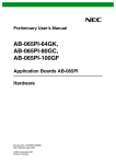
TM DeltaPoint Jr Installation and Operation Manual 6 GPM (22.7 LPM) Unit EMERGENCY 24 Hour Service Phone Number 877-684-0589 Effective with products having serial number 040817000 and greater, Firmware Revision 3.15 DPJMAN-1106 ROCON LLC 1755 East Nine Mile Road, Hazel Park, MI 48030 PH 248-542-9635, Fax 248-584-1490 www.flowmeters.com ROCON LLC TABLE OF CONTENTS TABLE OF CONTENTS ................................................................................................................................ 2 PROPRIETARY NOTICE .............................................................................................................................. 3 SPECIFICATION ........................................................................................................................................... 4 DIMENSIONS ............................................................................................................................................... 5 DeltaPoint Jr. Top View ............................................................................................................................. 5 DeltaPoint Jr. End View ............................................................................................................................. 6 HOW IT WORKS ........................................................................................................................................... 7 INSTALLATION ............................................................................................................................................. 8 ELECTRICAL CIRCUIT ................................................................................................................................ 9 JUMPER SETTINGS .................................................................................................................................. 10 SET-UP PROCEDURE ............................................................................................................................... 11 Configuring the Engineering Units ........................................................................................................... 11 Configuring the Flow Alarm ..................................................................................................................... 11 UNIT VERIFICATION.................................................................................................................................. 13 TROUBLESHOOTING ................................................................................................................................ 14 Unit Will Not Power Up ............................................................................................................................ 14 Unit Will Not Start .................................................................................................................................... 14 Insufficient Water Flow......................................................................................................................... 14 Water Continues to Flow When Cap is Removed ................................................................................... 15 Unit ....................................................................................................................................................... 15 Flowmeter ............................................................................................................................................ 15 Shut-Off Valve ...................................................................................................................................... 15 Check Valve ......................................................................................................................................... 15 Unit Will Not Restart Manually or Remotely ............................................................................................ 15 Unit ....................................................................................................................................................... 15 Flowmeter ............................................................................................................................................ 16 Shut-Off Valve ...................................................................................................................................... 16 Flowmeter Display Unstable .................................................................................................................... 16 Solenoid Valve Does Not Open ............................................................................................................... 16 Fault Alarm Signal Not Received at Weld Controller .............................................................................. 16 Flowmeter ............................................................................................................................................ 16 MAINTENANCE .......................................................................................................................................... 17 Flowmeter ................................................................................................................................................ 17 Inspect or Replace Bluff Assembly ...................................................................................................... 17 Shut-Off Valve ......................................................................................................................................... 17 Replace Coil ......................................................................................................................................... 17 Clean Diaphragm Orifice / Plunger Pilot Hole ..................................................................................... 17 Override Stem Broken ............................................................................................................................. 18 Check Valve/Remove Piston ................................................................................................................... 18 Cleaning................................................................................................................................................... 18 Note ......................................................................................................................................................... 18 MODEL CODES .......................................................................................................................................... 19 APPENDIX .................................................................................................................................................. 20 Specifications for DeltaPoint Jr ............................................................................................................... 20 Check Valve Specifications ..................................................................................................................... 21 Shut-Off Valve Specifications .................................................................................................................. 21 DeltaPoint Uno Elbow Test Results ........................................................................................................ 22 RMA NOTICE .............................................................................................................................................. 23 RMA FORM ................................................................................................................................................. 24 WARRANTY INFORMATION ..................................................................................................................... 25 2 ROCON LLC PROPRIETARY NOTICE The information contained in this publication is derived in part from proprietary and patented data. This information has been prepared for the express purpose of assisting in installation, operation, and maintenance of the instruments described herein. Publication of this information does not convey any rights of use or reproduction other than in connection with the installation, operation and maintenance of the equipment described herein. Universal Flow Monitors, Inc. and Rocon LLC reserve the right to change the information contained in this publication at any time and without prior notice. Serial numbers are generated by taking the last two digits of the year + month + a five-digit sequential number. 3 ROCON LLC GENERAL SPECIFICATION Maximum Operating Pressure: Minimum Operating Pressure: Temperature Ratings: Ambient: Fluid Media: Flow Rate: Flow Measurement Accuracy: Repeatability: Power Requirement: Alarm Output: Alarm Output Impedance: Electrical Connection: Wetted Parts: 150 PSI (10 bar) 10 PSI of back pressure is required for the formation of vortices. 14 F to 122 F (-10 C to 50 C) 176 F (80 C) Maximum 0.35 GPM Min. to 6.0 GPM Max. (22.7 LPM) ± 2% full-scale (± 0.2 LPM) 0.25% of actual flow 24 VDC @ 750 mA (18 Watts) Maximum (Solenoid Valve energized) 24V = Fault, 0V = OK 2K Ohms (internal pull-up resistor) Turck EURO FS4.6 Brass, PVDF, Viton, Buna N (NBR), EPDM, FKM, Beryllium Copper Caution: The unit shall be supplied by a SELV (separated extra-low voltage) source in accordance with CSA Standard C22.2 No.1010.1-92 Annex H. Environmental conditions: This device has been designed for use in Installation Category I, pollution degree 4, at altitudes up to 2000 meters (6560 ft.), either indoors or outdoors as defined in CSA Standard C22.2 No.1010.1-92. 4 ROCON LLC DIMENSIONS DeltaPoint Jr PUSH TO START PUSH TO BYPASS DeltaPoint Jr. Top View 5 ROCON LLC DeltaPoint Jr. End View 6 ROCON LLC HOW IT WORKS DeltaPoint Jr. is a cooling water flow switch. It is comprised of a flow sensor, a shut-off valve, a check valve, and all the associated wiring, complete in one package. When installed in the return leg, it can detect changes in water flow due to cap loss or a break in the line, and shut off the supply/return water legs. The flow sensor utilizes the vortex shedding principle and has no moving parts to wear or clog. The water strikes a bluff body, generating vortices (eddies) that move downstream. The vortices form alternately, from one side to the other. A piezoelectric sensor housed in a sensor tube directly downstream of the bluff senses the pressure zones created by the vortices. The sensor generates a frequency directly proportional to the vortices (flow). The microprocessor measures this frequency and displays the output. If installed according to the instructions in this manual, the 3-digit LED on the flow sensor displays the water flow rate in the “return” leg in either LPM (liters per minute) or GPM (gallons per minute) with a high degree of accuracy. Mounted on the box is a two-position switch which is used to start the unit for normal operation, or to bypass the solenoid valve by forcing it to remain open, even in case of a fault (during maintenance, for example). If water flow is present and is above the preset value, the flowmeter sends an OK TO WELD signal to the weld controller, allowing the weld cycle to start. This is a 0V signal coming from the internal solid-state relay. The shut-off valve is held open by the microprocessor during normal operation, and it closes when there is either a flow fault or a power failure. If a cap is pulled, the water flow in the “return” leg drops below the setpoint and the flow switch sends a FAULT signal (24VDC) to the weld controller. It also shuts off the solenoid valve, thus stopping the water flow in the “supply” leg. The check valve prevents water from flowing backwards from the gun arms, effectively preventing a water spill from any source. The rocker switch has two positions: START and BYPASS. START is a momentary switch that forces the valve to open. It is typically held down at startup for a few seconds, until all the air trapped in the weld gun arm circuit is removed and a steady stolid column of water is entering the flow switch. When the green light inside the START switch is lit, it indicates that the water flow is above the flow switch alarm setting and, therefore, is OK TO WELD. At this point the microprocessor takes over and continues to keep the valve open during operation. BYPASS is a toggle switch (push to turn on) and is used to force the valve open by overriding the internal logic circuit. When in bypass, the flow sensor continues to monitor the flow in this case, as indicated on the LED display, but the orange light (inside the BYPASS switch) is a visual reminder that the valve can no longer be closed if flow fault occurs. The shut-off valve has an independent LED that is built into its cable connector. When this LED is on it confirms the presence of coil power (valve should be open in this case). The factory made a change on the operation of the “Bypass” switch mode. Please review below. Serial Number 040817000 and greater. The unit will not allow you in “Bypass” mode and ignore alarm fault if no water flow is present or leak detected. Kit available (Part # “HBO”) to rework as described below. Serial Number 051200100 and greater. When the user activates the “Bypass” position of the switch, the unit will ignore the “Alarm Fault” signal from flowmeter. Please note: The user could weld without water to the weld guns in this mode. SOLENOID INTERRUPT (Option H) is active on all units. It is used to remotely shut off the water flow (Shut-Off Valve Coil) before the Associate changes weld gun arm electrodes. 7 ROCON LLC INSTALLATION There are no upstream or downstream piping requirements to achieve proper operation. Refer to page 22 to review requested water flow test using 90 degree elbow. The unit should be installed on the fence line for best results. The unit can be installed in any position as long as good piping installation requirements are adhered to. Unions of the same pipe size and full ported isolation valves may be installed for ease of servicing the unit and shutting off the water. Teflon® tape or pipe sealant can be used in mounting the unit to the piping system. Teflon® tape, if not applied properly to the connecting pipe, can become caught on the bluff and affect the flow measurement. Piping systems should be filled slowly to prevent water hammer from damaging sensor. Hold Down hole pattern - 2 holes, 5/16-inch (8 mm) diameter, inline and 6 3/16 inches (157 mm) apart. Porting – Supply and Return water ports - ¾ NPTF, To Cell and From Cell – ½ NPTF Flow path and Port Identification located switch box cover. Electrical Circuit – See page 10 Suggested Hose Dress: UPPER JAW SHUNT 1/2 INCH 3/8 INCH LOWER JAW TRANSFORMER IN TM ROC ON LLC FLO W R ATE 0.00 De l t a Po i n t U no AL AR M SE T OUT PUSH TO STA RT TM FROM CELL PUSH TO BYPASS ROCON LLC D ELTA P O I N T RETURN WATER TO CELL 17 55 E 9 MI LE RD., HAZEL PARK MI 480 30 PHONE 24 8-5 42- 963 5. WWW.RO CONL LC.CO M 2 4VD C ON LY MOD EL # SER IAL # SUPPLY WATER RETURN SUPPLY 8 9 SOLENOID VALVE - GREEN BLUE 2 BLACK + 1 _ + 10 ORG J3 1 2 3 VALVE 2 SJ3 1 2 SOLENOID INTERRUPT 1 JP3 J1 SWITCH GREEN LED 1 2 3 4 5 7 6 START YELLOW LED GRY 7 +24V 2 ORG BYPASS START GRN 6 SWITCH A G BYPASS BLK 5 BLK 8 WHT 3 BLK 1 START / BYPASS SWITCH D2 IN4004 +24V 2 - 1 + 4 - 3 + 2 2 D5 R1 D1 IN4004 IN4004 D4 IN4004 IN4004 D3 3.74 k SJ5 1 1 3 1 2 JP1 2 3 1 SJ1 2 2 SJ4 3 3 2 1 ALARM RESET 1 R2 3.74 k OUTPUT +24V 3 +24V JP4 RESET 1 RST CFG SJ2 2 DELTAPOINT JR. DC INTERFACE BOARD K1 70M-0DC 1 JP5 JP2 1 2 3 +24V VALVE VCC (4) BLK RESET (1) BRN +24VDC 3 GRN VCC BLK 6 J2 DELTAPOINT UNO 5 6 4 WHT ALARM 3 2 1 ORG 5 2 ORG VALVE OUT BLK 24V COM BLU RESET RED +24V (3) BLU CHASSIS GRD 3 6 4 NC NO (6) PINK SOLENOID INTERRUPT 02/08/2006 DELTAPOINT UNO FLOW METER 1 5 RECEPTACLE TURCK - 6 PIN, MICRO, FS4.6 (EOA) RED 4 WHT 3 BLU 2 GRN 1 (5) GREY ALARM (2) WHT 24VDC COMMON 3.47 k R3 J4 4 3 2 1 POWER PS2701-1 4 ROCON LLC ELECTRICAL CIRCUIT DPJ-A-6/4-6EF2D10-H-HA Firmware Version 3.15 ROCON LLC JUMPER SETTINGS DELTAPOINT JR. DC INTERFACE BOARD REV: X.XX XX/XX/XXXX (C) UNIVERSAL FLOW MONITORS DeltaPoint Jr - JUMPERS JP1 JP5 JP2 JP3 JP4 DeltaPoint Jr Interface Board Jumper Part # 7548 JP1 VOLTAGE = D2 - 24V PNP (SINKING) (0V A) 1 2 3 2 3 2 3 2 3 JP1 VOLTAGE = D1 - 24V NPN (SOURCING) (24V A) 1 JP2 RESTART SIGNAL = R - 24V ACTIVE HIGH 1 JP2 RESTART SIGNAL = 0 - 0V ACTIVE LOW 1 JP3 OPTIONS = H - SOLENOID INTERRUPT (No Jumper) 1 2 JP3 OPTIONS = N - NO OPTIONS PICKED 1 2 JP4 RESTART SIGNAL = R - 24V ACTIVE HIGH 1 2 3 2 3 JP4 RESTART SIGNAL = 0 - 0V ACTIVE LOW 1 JP5 RESTART SIGNAL = R - 24V ACTIVE HIGH 1 2 JP5 RESTART SIGNAL = 0 - 0V ACTIVE LOW (No Jumper) 1 2 10 ROCON LLC SET-UP PROCEDURE Configuring the Engineering Units In order to configure the engineering units (GPM or LPM), proceed as follows: 1. Press and hold the MENU pushbutton, the display shows “---”. Continue holding the pushbutton for at least 5 seconds. 2. The display shows either “G” (for GPM) or “L” (for LPM), depending on what engineering unit was previously set. 3. Release the ALARM SET pushbutton. 4. Use the ALARM SET pushbutton (press and release) to toggle between “G” and “L”, then do not touch the pushbutton until the flowmeter returns to normal operation. Note: It may take up to 20 seconds before the meter returns to normal operation. Do not touch the pushbutton unless you want to change the alarm setting, as described below. Configuring the Flow Alarm In order to configure the flowmeter for alarm output, proceed as follows: 1. Press and hold the ALARM SET pushbutton, the display shows “---”. Continue holding the pushbutton for at least 5 seconds. 2. The display shows either “G” or “L” depending on which engineering unit has been selected. 3. Wait 5 seconds. During the 5-second period, you can either continue holding the ALARM SET pushbutton, or release it. If you release the pushbutton, do not push it again. (If you press and release the pushbutton at this point, the display toggles between “G” and “L”, assuming that you are changing the engineering units.) 4. The 3-digit value that starts blinking on the display is the alarm setpoint (as stored in the memory). If you do not press ALARM SET, the display continues to blink for 10 seconds, then the meter reverts back to normal operation. 5. Use the ALARM SET pushbutton to change the alarm setpoint, if needed. Note: When ALARM SET is pressed once, the display stops blinking and increments to the next value. ALARM SET can either be held down continuously, or pressed and released repeatedly. When the maximum setpoint value is reached, the display rolls over to the minimum value again. Setpoint values are pre-programmed. Please refer to Table 1 (below) for more details. 6. When the desired alarm setpoint is displayed, do not touch the pushbutton for 10 seconds. The displayed value is saved in the memory and the meter returns to normal operation. Setpoint Min. Setpoint Max. Hysteresis Pre-programmed Increments LPM GPM LPM GPM LPM GPM LPM GPM 1.5 0.40 12.0 3.00 0.4 0.1 0.5 0.2 Table 1. Flow Alarm Range 11 ROCON LLC Note: Flow fault occurs when flow =< setpoint. The LED display starts blinking to indicate this. After the occurrence of a flow fault, the unit must be restarted. If in bypass mode, the alarm signal returns to normal when flow > setpoint + hysteresis (display stops blinking). 12 ROCON LLC UNIT VERIFICATION Initial Water Flow Present to Operate 1. Confirm that the hoses to weld gun arms are hose-dressed properly. Refer to the INSTALLATION section of this manual. 2. Open the water shut-off ball valves to weld gun arms or cell. 3. Plug in the Turck Euro connector to the unit. The flowmeter LED display lights up and shows the firmware revision, followed by a 5-second countdown (Restart delay). It then shows a blinking “0.00” to indicate that there is No Water Flow (Alarm Fault mode). 4. Press the BYPASS switch. The orange light turns on and the shut-off valve opens (Shut-off Valve Coil, DIN connector LED turned on). 5. Wait a few seconds for the water flow to stabilize, and then record the water flow as shown on the 3digit LED display (on the DeltaPoint Uno flowmeter nameplate). If yes, proceed to the next step. If no, see Troubleshooting – “Unit Will Not Start – Insufficient Water Flow.” 6. Alarm setpoint is 4.00 LPM (factory setting). 7. Change the BYPASS switch to START position. The orange light turns off and the green light remains on. Unit has passed basic water flow setup test (sufficient water flow present to keep the unit in operation). Flow Fault Verification – Cap Pulled 8. Pull upper weld gun arm cap off. 9. The LED display on the flowmeter is reading “0.00” and flashing. If yes, proceed to the next step. If no, see Troubleshooting – “Water Continues to Flow When Cap is Removed.” 10. Fault alarm signal received at weld controller and robot stops welding. If yes, proceed to next step. If no, see Troubleshooting – “Fault Alarm Signal Not Received at Weld Controller.” 11. Water is off (not leaking at the gun arm). Shut-off and check valves closed and the LED on the DIN connector to the shut-off valve coil is turned off. If yes, proceed to next step. If no, see Troubleshooting – “Water Continues to Flow When Cap is Removed.” 12. Replace cap and upper gun arm. Press the START switch and hold it down until the green light turns on. This forces the shut-off valve to remain open until water flow is stabilized throughout the system (flow above 4.00 LPM). 13. Release the START switch. The unit should continue to operate normally. If yes, proceed to next step. If no, see Troubleshooting – “Unit Will Not Start – Insufficient Water Flow.” 14. Perform steps 9 thru 13 on the lower weld gun arm. 15. If all steps are completed satisfactorily, the unit has passed the basic “cap pull” test. (Cap pulled, fault alarm received at weld controller, water was shut off and no leaks were observed.) It is ready for the next step. Flow Fault Verification – Water Flow Shut off or Below 4.00 LPM 16. Close the supply water leg ball valve to weld gun arms or close until below 4.00 LPM. 17. Repeat steps 9 thru 13 from “Flow Fault Verification – Cap Pulled.” 18. If all steps are completed satisfactorily, unit is ready for final test. System Verification – Restart Unit Remotely 19. Close the return water leg ball valve from weld gun arms. 20. Unit shuts off water, LED flashing “0.00”, and sends fault alarm to weld controller. 21. Open the return leg ball valve. 22. Restart unit remotely. If yes, unit is ready for production operation. If no, see Troubleshooting – “Unit Will Not Restart Manually or Remotely.” 13 ROCON LLC TROUBLESHOOTING Unit Will Not Power Up 1. Make sure the power cable is correctly plugged into the unit. The DeltaPoint Uno flowmeter display shows a 3-digit number (bright-red digits). It may or may not be flashing. 2. Check the connector on J4 (see ELECTRICAL CIRCUIT) to ensure that the 6-pin receptacle is plugged in correctly to the board. 3. If the power cable is plugged in correctly, and you have ensured that the 24 V is present, unit must be replaced. Contact factory for RMA number, and a box for shipping if necessary. Unit Will Not Start **The flowmeter requires a minimum of 1.5 LPM (0.4 GPM) to operate. If water flow is below minimum, the display will blink 0.00 and send a fault alarm. The following tests determine the amount of water flow available, if the hose or fittings are restricting water flow, or if the weld gun arms are faulty.** Insufficient Water Flow Suggested procedure to confirm amount of water flow available or if there is some restriction in the circuit: 1. Turn water off by closing the water shut-off valves. 2. Remove hoses “TO CELL” and “FROM CELL” from the unit and install a 5-foot hose loop between them (the loop will be the same hose size and mating fitting). 3. Open the water shut-off valves. 4. Power up the unit. Does the flowmeter indicate water flow? If yes, proceed to next step. If not, contact supervisor. **Unit indicates that water is present. The next step is to determine if there is a blockage or hose dress problem between the unit and the weld gun arms.** 5. Close the water shut-off valves, remove the 5-foot hose loop, and reinstall the gun arm hoses to the unit. 6. Remove the hoses at the manifold (or tee) just before they are divided into 2 separate hoses to each weld gun arm. 7. Connect the supply and return hoses together and turn the water shutoff valves open. 8. Power up the unit. Does the flowmeter indicate water flow? If yes, proceed to next step. If no, inspect hose and fitting for a blockage, i.e. the fitting is not drilled through, or dirt is blocking flow in hose or fitting, or hose is kinked. **Unit indicates that water is present. The next step is to determine if there is a blockage in the weld gun arms.** 9. Close the water shut-off valves. Connect the hoses to the manifold. 10. Turn the water back on. 11. Power up the unit. Does the flowmeter indicate water flow? If yes, unit is working. If no, inspect hose, fitting and weld gun arms for a blockage, i.e. the fitting is not drilled through or dirt is blocking flow in hose or fitting. The hose dress may be incorrect. The water tubes are too close to the caps, or the water tube is pinched, or the weld gun arms have never been tested for water flow and must be disassembled. Supervisor: Above testing indicated no water flow from main header to hose drops to cell. Please confirm that: (1) the number of pumps in operation is correct for a normal production day; (2) the headers to zone in question are operational and no bypass valves are open; and (3) no shut-off valves have closed, thus blocking the water flow through the header. Check for air buildup in the cooling header circuit. Since electrode tips are replaced daily, small amounts of air can leak into, and get trapped, in the piping. The rusty water that is observed in closed-loop cooling systems is the result of this trapped air. Please note that trapped air can also damage the flow sensor. The vortex flowmeter requires that there is continuous presence of water moving past the bluff body. If there is any air in the line, water hammering can fracture the internal components of the sensor. 14 ROCON LLC Check to determine if air is trapped in the cooling water circuit. Remove the hoses TO CELL and FROM Cell. Attach a 5-foot plastic (see-through) loop hose between TO CELL and FROM CELL on the unit. Power up the unit. Use a flashlight to look through the plastic hose and see if air bubbles are present in the water line. If this is the case, you need to purge the pipes. If you cannot see any air bubbles through the plastic hose, the header system is operating normally. Water Continues to Flow When Cap is Removed Unit 1. Make sure the 2-position switch is not in Bypass. 2. Make sure the switch is not stuck in Start position. Flowmeter 1. Check if the shut-off signal is transmitted by the flowmeter. See ELECTRICAL CIRCUIT. Pin 5 of J2 should go low in order to shut off the solenoid valve. This can be verified by checking the voltage on Pin 1 of JP5. If this pin is high, there may be a damaged component on the circuit board. Consult factory for further assistance. 2. If the shut-off signal from the flowmeter is low, check the LED on the solenoid valve DIN connector. If this LED is on, there may be a short either in the cable or on the circuit board. Neither one of these problems can be fixed in the field. Consult factory to arrange for an RMA. Shut-Off Valve **Check the manual bypass screw on the solenoid valve. The stem should be in the Normal position.** 1. Close the supply and return ball valves. Remove both weld gun arm caps. Gradually turn the supply ball valve ½ turn. If at any time water begins to leak through the weld gun arms (water tube orifice), the problem lies within the solenoid valve. If no leak is detected, refer to Check Valve leak procedure below. 2. If solenoid valve is the source of the problem, there are three possible reasons: (1) the orifice in the diaphragm is plugged; (2) a foreign object is trapped between the valve seat and the diaphragm; (3) the internal pilot hole is blocked between the plunger and valve cover. See MAINTENANCE for required tools and procedure to disassemble valve. Check Valve 1. Close the supply and return ball valves. Remove both weld gun arm caps. Gradually turn the return ball valve ½ turn. If at any time water begins to leak through the weld gun arms (around the water tube), the problem lies within the check valve. If no leak is detected, check for proper hose dress. 2. Remove the check valve from manifold. See MAINTENANCE for required tools and procedure. 3. Check valve inspection - With a flat nose screwdriver, push the piston back and forth to make sure it moves freely. If not, remove the piston from the housing. If it moves freely but you can see a foreign object on the seat, run some water through it to dislodge the object. If you cannot remove the foreign object, then either replace the check valve or see MAINTENANCE, “Check Valve/Remove Piston.” 4. Reinstall the check valve after cleaning. Be careful about the flow direction on the check valve. Unit Will Not Restart Manually or Remotely Unit 2-Position Switch Defective - If the lights in the switch do not activate when the unit is powered up, replace the switch. Reset Signal and Jumpers – See ELECTRICAL CIRCUIT and JUMPER SETTINGS while testing the following: 1. Check the Reset signal (Pin 4 of the receptacle) for correct polarity. It should be “Active Low” (signal going low issues a Restart). 15 ROCON LLC 2. Check the solenoid interrupt line (Pin 6 of the receptacle) and make sure it is low. 3. Check the jumper settings on JP2, JP4 and JP5. Make sure they are all set for “Active Low.” Flowmeter See TROUBLESHOOTING, “Unit Will Not Start”, to ensure sufficient water flow is available for flowmeter to operate. Shut-Off Valve Internal Plunger Pilot Hole May Be Plugged The following procedure will determine if pilot is the problem. 1. Close the water supply and return ball valves. 2. Turn the manual bypass stem on the shut-off valve 90 degrees to the Bypass position. See the shut-off valve “Manual Override” illustration under MAINTENANCE. 3. Open the water supply and return ball valves. 4. Does the flowmeter indicate water flow? If yes, see MAINTENANCE – “Shut-Off Valve, Clean Diaphragm Orifice/Plunger Pilot Hole.” If no, consult factory. Flowmeter Display Unstable 1. Check Unit Will Not Start to ensure that no air is trapped in the water line. Also, a foreign object trapped on the bluff could cause an unstable condition. See MAINTENANCE for the required tools and the proper method to remove the bluff. 2. Close water supply and return ball valves. 3. Remove the power connector from the unit. 4. Put the shut-off valve manual bypass stem in the bypass position. See the shut-off valve “Manual Override” illustration under MAINTENANCE. 5. Remove the bluff stem underneath the DeltaPoint Uno flowmeter, and clean if dirty. Turn the “Supply” water shut-off valve open ¼ turn or until water is slowly flowing out of the bluff mounting hole. (This is to ensure that air does not leak into the piping.) 6. Replace the bluff; turn the shut-off valve manual bypass stem back to normal position. Open the supply water valve and connect the power cable to the unit. If the display is normal, unit is ready for operation. If not, consult factory. Solenoid Valve Does Not Open 1. Make sure there is power to the unit. 2. Push BYPASS switch (orange light on). 3. Check the LED on the solenoid valve DIN connector. If the light is not on, the problem may lie in the internal wiring. Contact the factory for further instructions. 4. If the light is on, make sure the valve connector is plugged in tightly. If this does not fix the problem, replace the coil (see MAINTENANCE). Fault Alarm Signal Not Received at Weld Controller Flowmeter 1. Make sure the flowmeter is indicating flow fault (3-digit LED flashing). 2. Check the setting of JP1 (see JUMPER SETTINGS). 3. Check the connector on J4 (see ELECTRICAL CIRCUIT) to ensure that the 6-pin receptacle is plugged in correctly to the board. 4. Check the voltage on Pin 2 of the 6-pin receptacle (see ELECTRICAL CIRCUIT). This pin should be high in fault mode. Supervisor: If Steps 1-3 checked out okay, please check for proper wiring between the unit and the weld controller. 16 ROCON LLC MAINTENANCE Flowmeter (4 GPM – Model Code ¼) Inspect or Replace Bluff Assembly Tools required: #4 Allen wrench; clean paper towels within easy reach. Spare parts: Bluff body PN# 7482-2, O-Ring PN#345 (2-010), Reference 4-40 x ¼ lg stainless socket head screw PN# 109, approved O-Ring lube. 1. Procedure to remove bluff: 1.1. Place unit on clean surface upside down. 1.2. Remove both #4-40 SSHS with the #4 Allen wrench. 1.3. Pull the bluff from the body. Note the flat side of the bluff flange head. The orientation of the flat side is critical when reassembling the unit. 1.4. Remove the O-ring. 1.5. Inspect bluff for wear or foreign material wrapped around it. 1.6. Inspect the O-Ring to see if it needs to be replaced. 1.7. Clean bluff with soap and water or simply replace it with a new one. 2. Procedure to reinstall bluff: 2.1. Install O-ring (P/N 345 (2-010)) with light coating of approved O-ring lube oil into counter bore in body. Make sure that the O-ring is not twisted. 2.2. Insert the bluff into the body. Note that the flat on the bluff flange head will only allow the bluff to be installed in one position. Secure the bluff to the body using (2) #4-40 x ¼ lg. stainless socket head screws P/N 109. Do not over-tighten. Shut-Off Valve Replace Coil Tool Required: No Tools Required Spare Parts: #2705-24V-COIL Remove the DIN connector with the Phillips screwdriver and pull from coil. 1. Pull spring clip from side of coil until you can remove coil off Guide. 2. DC Coil part number #. 3. Install new coil, push spring clip inward over coil and plug in DIN connector to coil. 4. Test to determine if coil is operational. 5. If there are problems, contact Service Department at Rocon LLC - 248-542-9635. Clean Diaphragm Orifice / Plunger Pilot Hole Tools required: #4 Allen wrench, 22 mm Open End Wrench 1. Remove the DIN connector with the Phillips screwdriver. 2. Remove coil by pulling spring clip outward until coil can be removed. 3. Remove the 4 socket head screws with the #4 Allen wrench. 4. Gently pull the valve cover upward. Caution: Pressure spring is located in valve cover. 5. With valve cover and pressure spring removed, the diaphragm is sitting on the valve body. 6. Lift diaphragm off its seat and examine. Remove any foreign material on the diaphragm with soap and water. 7. Hold the diaphragm up to light source. Observe small orifice below the pilot hole in diaphragm. If it is plugged, remove dirt with soap and water. Replace diaphragm in valve body with 4 guide legs going in first and the outer pilot hole fitting into the valve body molded surface. 8. With the valve cover upside down, direct flashlight into the pilot hole. If you suspect hole is plugged, you will have to remove the screw piece and the guide with the inch box wrench. 9. The guide encloses the pressure spring and plunger. Spring fits inside the plunger. 10. With the guide and screw piece removed, check the orifice for any foreign matter. If present, remove with soap and water. 17 ROCON LLC 11. To reassemble: Spring fits into the top of the plunger. The plunger fits inside the guide with the spring going in first. The plunger seat fits on top of the orifice seat. With plunger in place, screw the screw piece into the valve cover. 12. With the valve cover complete, set the pressure spring on top of the diaphragm and the valve cover on top of the pressure spring. Install the 4 socket head screws. 13. With the spring clip pulled, slide the coil over the guide. When complete, push the spring clip over the coil. 14. Insert the DIN connector into the coil. 15. Energize coil to confirm operation. If there is a problem, consult Service Department at Rocon LLC. Override Stem Broken Spare Part: # 2705-CAP If the override stem is broken, replace the control cover. An indication of a broken stem is that the valve will not shut off in fault (or when power is removed), while the stem is in Normal position. This is determined when the valve is disassembled and no foreign object was found that would force open the diaphragm. Check Valve/Remove Piston Tools Required: 1 3/16” box wrench to remove from unit, retainer ring puller, ¼ inch flat nose screwdriver Spare Part: Check Valve #2081 1. Remove the retainer ring. 2. Gently push the piston (water flow OUT side) with the screwdriver until dislodged. The O-ring remains in place. Only the spring and the piston are removed. Clean with soap and water. 3. Check if the O-ring needs replacement. 4. Insert the spring over the piston and insert them into return port. 5. Replace the retainer ring. 6. Test to confirm that the unit is operational. If there are problems, contact the Service Department at Rocon, LLC. Cleaning These meters do not require any special cleaning of the external surfaces. If cleaning is deemed necessary, strong solvents, detergents, or chemicals should not be used. A damp cloth may be used to wipe off dirt or debris. Note If used outside the parameters specified in this manual, the proper operation of the flowmeter cannot be guaranteed. 18 ROCON LLC MODEL CODES DeltaPoint Jr EXAMPLE : DPJ - B -6 - Port/Pipe Size Port/Pipe Size 4 Digit Number assigned at Factory FLOW SWITCH RANGE in Inches NPT in Inches NPT for Supply and for Pipes To Return Lines and From Cell followed by alpha code: Symbol 0.4 - 4.0 GPM (2 - 15 LPM).............3/4.....................1/2............. = A-6/4 0.4 - 4.0 GPM (2 - 15 LPM).............3/4.....................3/4............. = A-6 1.2 - 12 GPM (5 - 45 LPM).............3/4.....................3/4............. = B-6 2.5 - 25 GPM (9 - 95 LPM).............3/4.....................3/4............. = C-6 19 XXXXD Example XXXXD = DC The 4 digit code covers: Connectors style, number of pins, wire color and function. Alarm type, restart type and any options picked. ROCON LLC APPENDIX Specifications for DeltaPoint Jr (See page 4 for complete device specifications) Mechanical Maximum operating pressure: Minimum operating pressure: Maximum operating temperature: Minimum operating temperature: Maximum Flow: Minimum Flow: Wetted Parts: Power Requirement: Display: 190 PSIG (12.9 Bar) See Chart 210 °F (99 °C) Fluid 40 °F (4 °C) Fluid 4.0 GPM (15 LPM) 0.4 GPM (1.5 LPM) Brass, PVDF and Viton 10–30 VDC @ 80 mA 3-digit LED digital display, 0.3” high PRESSURE DROP CHARTS 12 10 8 5 1000 750 500 350 200 2 100 1 50 35 .5 20 .2 10 .1 5 3.5 .05 .3 .6 1 2 5 10 15 25 50 100 250 200 300 2 FLOW (GPM) 5 10 20 30 50 100 200 600 1200 300 800 FLOW (LPM) Electrical Accuracy: Repeatability: Alarm Output: Alarm Deadband: Alarm State: Electrical Connection: ± 2% full-scale (± 0.3 LPM) 0.25% of actual flow Solid-state relay rated to 125 mA @ VDC, up to 185 °F (85 °C); 50 mA @ 30 VDC between 186-210 °F (86–99 °C) 2.5% of full-scale NO (24VDC) or NC (0VDC) with internal 2K pull-up resistor (factory setting ONLY) Direct cable to junction box 20 ROCON LLC Check Valve Specifications Style: Maximum operating pressure: Maximum operating temperature: Cracking Pressure: Material: Piston Check Valve with embedded O-ring that seals on seat 500 PSI (34.5 bar) 180 °F (82 °C) 1 PSI Brass Body and Piston, Beryllium Copper Ring Shut-Off Valve Specifications Function: Ports: Pressure Range: Temperature Ratings: Ambient: Fluid Media: Coil Power Rating: Electrical Connector: Materials of Construction: Body: Seal: Other Wetted Parts: Coil: 2-Way Normally Closed ¾” NPT 2 PSI to 150 PSI (0.14 bar to 10 bar) 14 F to 122 F (-10 C to 50 C) 176 F (80 C) Maximum 24VDC @ 700 mA (16 Watts) Maximum DIN Style Plug w/ Removable Cable Plug Adaptor Brass Buna N Stainless Steel, PVDF, Brass Class F, Molded, Continuous Duty, UL & CSA Listed Contact Factory for Spare Parts Manual Override (Bypass) Normal Operation Manual Override Position - 90 Degrees ONLY! Normal Operation KIP/NORGREN VALVE Manual Override Position PARKER VALVE 21 ROCON LLC DeltaPoint Uno Elbow Test Results DELTA POINT UNO WATER FLOWMETER TEST With and Without 90 Degree Fitting Installed Inlet Port 2.00 A 2.00 A Master Flow Meter Master Flow Meter 2.00 B DeltaPoint Uno C A = Master GPM 1 2 3 4 B = DP Uno Increasing 0.98 1.97 2.96 3.96 B = DP Uno Decreasing 0.99 1.98 2.96 3.95 C = DP Uno Increasing 0.98 1.98 2.96 3.98 Based on the above results, there is no difference in performance in the installation of a 90 degree fitting in the inlet port of the flow switch on the DeltaPoint Jr unit. 22 C = DP Uno Decreasing 0.95 1.99 2.98 3.99 ROCON LLC RMA NOTICE RMA NOTICE RETURN MATERIAL AUTHORIZATION Please read the following UFM policy information carefully. By following the guidelines outlined below you will assist in providing a timely evaluation and response regarding the status of your flow meter. UFM evaluates all AUTHORIZED RETURNED MATERIALS in a timely manner and will promptly provide notification regarding the status of the related materials and/or a written quotation indicating the total charges and description of the necessary repairs. 1 2 3 4 5 All returns must have a RMA form completed by the customer. Any meter returned that was previously in service must have the OSHA requirements completed and a MSDS included where applicable. An RMA number will only be issued when UFM has received a copy of the completed RMA form and any applicable MSDS. A "Return Goods" shipping label (located in the back of the Instruction Manual) must be used for returning materials to UFM. Returned goods must be shipped prepaid or they will be rejected. REPAIRABLE MATERIAL Written or verbal authorization to proceed with the repair under an assigned Purchase Order, must be received within 30 days of repair quotation. If the unit(s) are repaired, the $90.00 evaluation charge will be applied to the quoted repair costs. If no repairs are authorized within this 30 day period, the customer will be billed $90.00 plus shipping charges and the materials will be returned to the customer. NON-REPAIRABLE MATERIAL If materials are found not repairable, a written notice that the material is not repairable will be provided to the customer by UFM. If no disposition to scrap or return the material is received from the customer within 30 days, unrepairable material will be scrapped and the customer will be billed the $90.00 evaluation charge. If a UFM replacement unit is purchased within 30 days of non-repairable condition notice, the $90.00 evaluation fee will be waived. The return of non-repairable materials may be ordered by customer Purchase Order providing for shipping and handling charges. RETURN FOR RESTOCK All goods returned for restock adjustment must be: A. New and unused. B. Returned to the factory within ONE YEAR of date of original shipment. C. Returned through the distributor where the goods were originally purchased. This material will also be subject to an evaluation charge of $90.00. The customer will be advised of the restocking adjustment for all restockable goods. Upon acceptance of the restocking adjustment, by the customer, the $90.00 evaluation fee will be waived and a credit issued by UFM. The customer will be advised of any non-restockable goods and will be charged the $90.00 evaluation fee plus any shipping charges if returned to the customer. If no disposition is received by UFM within 30 days, the goods will be scrapped and the $90.00 evaluation fee will be billed. WARRANTY RETURNS Warranty returns must be shipped prepaid to UFM. UFM will review the goods and advise the customer of the evaluation and validity of the warranty claim. Valid warranty claims will be repaired or replaced at no charge. No evaluation fee will be charged for repairs made under warranty. Return shipping costs will be prepaid by UFM. Should UFM determine the returned material is not defective under the provisions of UFM's standard warranty; the customer will be advised of needed repairs and associated costs. All materials returned for warranty repair that are determined to not have a valid warranty claim will be subject to the "Repairable Material" policy outlined above. 23 ROCON LLC RMA FORM 24 ROCON LLC ROCON / DELTAPOINT WARRANTY 1) ACCEPTANCE AND INTEGRATION CLAUSE: This Sales Order Acknowledgment and the sales order information that Rocon LLC attaches to or associates with it (this “Acknowledgement”), constitutes an acceptance by Rocon of an offer by the buyer upon the conditions and terms and at the prices stated in this Acknowledgement. This Acknowledgment contains the entire understanding of Rocon and the buyer regarding the subject matter of this Acknowledgement. This Acknowledgement may only be modified by a writing signed by the party against whom enforcement is sought. 2) WAIVER: Waiver by Rocon of any default(s) by the buyer shall not constitute waiver by Rocon of any of the conditions of the agreement between Rocon and the buyer as set forth here under with respect to any further or subsequent default by the buyer. 3) FORCE MAJEURE: Rocon shall not be responsible for failure or delays in deliveries due to fire, strikes, breakdowns, acts of God, failure of carriers, inability to secure required materials, or other causes beyond Rocon's control. Buyer waives any claims for damage arising by virtue of delay in delivery of material by Rocon. 4) LIMITED WARRANTY: (a) Warranty: For a period of one year from the date of manufacture, Rocon warrants that each product covered by this Acknowledgement will be free from defects in material and workmanship. In order to qualify for any remedy provided in this Acknowledgement, buyer must give notice to Rocon within the one-year period, return the product to Rocon freight paid and intact with Material Safety Data Sheets covering all substances passing through the product or that form a residue on the product. (b) Exclusive Remedy. The buyer's EXCLUSIVE REMEDY for failure of any product to conform to any warranty or otherwise for any defect is, at Rocon’s sole option, (i) repair, (ii) replacement, or (iii) refund of the entire purchase price for the specific product. Without limiting the foregoing, in no case will Rocon be liable for deinstallation of any defective product or installation of any repaired or replacement product THIS REMEDY IS THE EXCLUSIVE REMEDY AVAILABLE TO THE BUYER OR ANY OTHER PERSON. ROCON SHALL NOT BE LIABLE FOR ANY DIRECT, INDIRECT, INCIDENTAL, CONSEQUENTIAL, SPECIAL, PUNITIVE, OR OTHER DAMAGES IN CONNECTION WITH ANY CAUSE OF ACTION, WHETHER IN CONTRACT, TORT, OR OTHERWISE. (c) Disclaimer of Other Warranties. The express warranty in this Acknowledgement is in lieu of any other warranty, express or implied. Without limiting the foregoing, ROCON DISCLAIMS THE IMPLIED WARRANTY OF MERCHANTABILITY AND ANY IMPLIED WARRANTY OF FITNESS FOR A PARTICULAR PURPOSE. 5) Products purchased by OEMs (original equipment manufacturers) are warranted only for the specific programs (installations for specific customers) designated when so identified. 6) Flow sensors are warranted for 5 years, electronic parts for 2 years and ancillary check valves and shut off valves for 6 months. 25