1
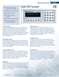
1. 85776
Polarization Measurement Station
Model 2881
Operating Manual
Version 1.0
Part # 03637
Copyright Information
This manual and its contents, designs, drawings and specifications are considered Proprietary or
Confidential information by Polarean, Inc.
Any unauthorized reproduction or dissemination of the information contained herein is strictly
prohibited without the express consent and written authorization by Polarean, Inc.
Polarization Measurement Station Operating Manual
Copyright © 2012
Polarean, Inc.
2500 Meridian Parkway, Suite 175
Durham, NC, 27713, USA
Version 1.0
Table of Contents
1. 1. Introduction
Chapter Guide ................................................................................................................................... 2
Document Conventions ..................................................................................................................... 2
Abbreviations .................................................................................................................................... 2
Revision History ................................................................................................................................ 6
2. 2. Safety and Precautions
EMERGENCY SHUTDOWN INSTRUCTIONS ................................................................................. 1
Warnings and Precautions ................................................................................................................ 1
Revision History ................................................................................................................................ 2
3. 3. Polarization Measurement Station Specifications
Electrical Requirements: ................................................................................................................... 1
Settings ............................................................................................................................................. 1
Calibration ......................................................................................................................................... 2
Revision History ................................................................................................................................ 2
4. 4. Startup, Shutdown and Cleaning of the Polarization Measurement Station
Powering Up the Polarization Measurement Station ......................................................................... 1
Powering Down the Polarization Measurement Station .................................................................... 2
Cleaning the Polarization Measurement Station ............................................................................... 2
Revision History ................................................................................................................................ 2
5. 5. Measuring Hyperpolarized 3He and 129Xe
Determining the Presence of Hyperpolarized 3He or 129Xe in a Gas Sample.................................... 1
Determining the Level of Polarization of Hyperpolarized 3He or 129Xe in a Gas Sample .................. 4
Verifying 1-Liter Dose Bag Fill Volume (optional dose bag height gauges required) ........................ 6
Storage of Hyperpolarized Gas in a Static Magnetic Field ................................................................ 8
Revision History ................................................................................................................................ 8
6. 6. Maintenance Procedures
Maintenance Schedule...................................................................................................................... 1
Checking Polarimetry Circuit Functionality ........................................................................................ 1
Adjusting the Magnetic Field for Gas and Circuit Resonance ........................................................... 3
Revision History ................................................................................................................................ 4
Version 1.0
Appendix
1.
A. A. Using the Computer Applications
Polarimetry (version 4.x) ................................................................................................................... 1
Navigating the Data Acquisition View ............................................................................................... 2
Gas Sample Settings: Pressure, Blend, and Pulse Parameters ....................................................... 3
Performing Data Acquisitions ............................................................................................................ 4
Running a T1 Study (Spinning Up/Spinning Down) ........................................................................... 4
Viewing Polarimetry Inventory Information ........................................................................................ 6
Viewing Polarimetry Configuration .................................................................................................... 7
Polarimetry Error Messages .............................................................................................................. 8
Revision History ................................................................................................................................ 8
Version 1.0
Model 2881 Operating Manual
Version 1.0
Chapter 1:Introduction
Page 1 of 6
1
1. Introduction
Welcome to Polarean’s 2881 Polarization Measurement Station for hyperpolarized
3He and 129Xe. Using the Polarization Measurement Station, a trained operator
can perform the following procedures:
1. Determine the presence of hyperpolarized 3He and/or 129Xe in an
unknown or partially known gas sample
2. Measure the percentage of polarization in a gas sample of 3He or 129Xe
with known isotopic fraction of constituents
3. Determine with >95% certainty if the volume of a gas sample in a
standardized dose delivery bag is between 0.9 and 1.1 standard liters
(optional bag height verification gauges are required)
4. Hold a dose delivery bag filled with hyperpolarized 3He or 129Xe in a
static magnetic field to provide a gas relaxivity constant (T1) of greater
than 60 minutes (assuming no paramagnetic contamination of the
sample).
These procedures are explained in detail in the rest of this manual.
Model 2881 Operating Manual
Version 1.0
Chapter 1:Introduction
Page 2 of 6
Chapter Guide
This manual is divided into the following chapters:
1. Chapter 1, Introduction — introduces the Polarization Measurement Station
and explains the procedures that can be performed
2. Chapter 2, Safety and Precautions — explains emergency procedures for the
Polarization Measurement Station
3. Chapter 3, Polarization Measurement Station Specifications — contains
operational requirements and settings.
4. Chapter 4, Startup, Shutdown and Cleaning of the Polarization Measurement
Station — lists instructions for powering on and off the unit and cleaning
instructions.
5. Chapter 5, Measuring Hyperpolarized 3He and 129Xe — describes all of the
different measurements that can be performed with the unit
6. Chapter 6, Maintenance Procedures — explains the periodic procedures you
may need to do to maintain your Polarization Measurement Station
7. Appendix A, Using the Computer Applications — describes how to use the
Polarimetry software in more detail
Document Conventions
Emphasized text appears in italics. For example:
•
All operators must read this guide before operating the Polarization
Measurement Station or any piece of equipment contained within.
•
Use of the Polarization Measurement Station without a current calibration may
result in incorrect measurements.
A note contains information that is helpful, but not crucial to the task at hand.
For example:
Note:
The identity of the hyperpolarized gas (3He or 129Xe) is determined
solely by the current through the Helmholtz coils being within one of
the acceptable ranges stated in Chapter 3.
A warning contains information that, if ignored, may harm the operator or the
equipment. A list of standard warning symbols used in this manual is provided
below.
Model 2881 Operating Manual
Version 1.0
Chapter 1:Introduction
Page 3 of 6
Warning Symbols
The following warning symbols may be used in this manual and/or on the unit:
1
This symbol is intended to alert the operator to the presence of
important operating and maintenance instructions.
2
This symbol is intended to alert the operator to the danger of
exposure to magnetic fields.
3
4
This symbol specifies model number, serial number
and the manufacturing date of the instrument.
This symbol is intended to alert the operator to the presence of
dangerous voltages that may be of sufficient magnitude to
constitute a risk of electric shock.
5
This symbol specifies the load rating and circuit
breaker current limit installed on the
instruments.
6
This symbol is intended to alert the operator that the timing or
precision of a specific step in the operating procedures is critical to
achieving a high polarization yield or obtaining an accurate
estimate of polarization level.
Model 2881 Operating Manual
Version 1.0
Chapter 1:Introduction
Page 4 of 6
Warning Symbol Locations
The diagrams on the next page show the location of warning labels affixed to the
Xenon polarizer.
Model 2881 Operating Manual
Version 1.0
Chapter 1:Introduction
Page 5 of 6
Abbreviations
The following table lists the abbreviations and acronyms that may be used in this
manual.
Table 1: Abbreviations and acronyms
Abbreviation/
Acronym
Meaning
DC
Direct current
He
Helium
Hz
Hertz
ID
Identity
kHz
Kilo-Hertz (equivalent to 1000 Hz)
LED
Light-emitting diode
m
Meter(s)
NMR
Nuclear magnetic resonance
VAC
Volts of alternating current
Xe
Xenon
Model 2881 Operating Manual
Version 1.0
Chapter 1:Introduction
Page 6 of 6
Revision History
Date
Change
By whom
5/1/2012
Initial release
Polarean, Inc.
Model 2881 Operating Manual
Version 1.0
Chapter 2:Safety and Precautions
Page 1 of 2
2
2. Safety and Precautions
All operators must read this guide before operating the Polarization
Measurement Station or any piece of equipment contained within.
Operation of the Polarization Measurement Station without the proper
training could result in incorrect results being obtained for the
measurements.
EMERGENCY SHUTDOWN INSTRUCTIONS
To shut down the Polarization Measurement Station in an emergency
situation, toggle the illuminated red switch on the power strip at the
back of the unit or unplug from the wall outlet.
Warnings and Precautions
The Polarization Measurement Station generates a low-level
magnetic field (up to 50 Gauss). It is unknown if this field would
potentially affect electronic medical implants (e.g. cochlear implants,
pacemakers, etc.) or other magnetically sensitive materials or
equipment. All persons with electronic medical implants and all
magnetically sensitive materials and equipment should be kept
further than 3 feet (1M) away from the electromagnetic coils.
•
All operators of the Polarization Measurement Station must have been
trained by Polarean in proper usage and safety precautions.
•
There are no user-serviceable parts inside the unit and the outer panels must
be kept on at all times. Only Polarean service personnel must perform any
required maintenance, service or re-installation of software on the
Polarization Measurement Station. Certain maintenance and calibration
procedures can be performed by trained operators.
Model 2881 Operating Manual
Version 1.0
Chapter 2:Safety and Precautions
Page 2 of 2
Revision History
Date
Change
By whom
5/1/2012
Initial release
Polarean, Inc.
Model 2881 Operating Manual
Version 1.0
Chapter 3:Polarization Measurement Station Specifications
Page 1 of 2
3
3. Polarization Measurement Station
Specifications
Electrical Requirements
Table 2: Electrical requirements by model
Model No.
Values
02881
120 VAC, 60 Hz, up to 5 Amperes
12881
120 or 220 VAC (must be factory-configured), 50/60 Hz, up to 5
Amperes
Settings
Use these Helmholtz coil current settings depending on the type of
hyperpolarized gas being measured:
Table 3: Helmholtz coil current settings
Gas type:
Initial Value
Acceptable Range for Gas ID Test
3He
0.81 Amperes DC
0.70 to 0.90 Amperes DC
129Xe
2.32 Amperes DC
2.00 to 2.50 Amperes DC
Model 2881 Operating Manual
Version 1.0
Chapter 3:Polarization Measurement Station Specifications
Page 2 of 2
Calibration
The Polarization Measurement Station will be calibrated at time of installation
and must be re-calibrated annually (regardless of use) by a Polarean service
technician. Please contact Polarean to arrange a calibration service visit when
required. The calibration can be alternatively performed by a trained operator
using a Spin Transfer Standard, which can be provided by Polarean upon request.
Use of the Polarization Measurement Station without a current calibration
may result in incorrect measurements.
Revision History
Date
Change
By whom
5/1/2012
Initial release
Polarean, Inc.
Model 2881 Operating Manual
Version 1.0
Chapter 4:Startup, Shutdown and Cleaning of the
Polarization Measurement Station
Page 1 of 2
4
4. Startup, Shutdown and Cleaning of the
Polarization Measurement Station
Powering Up the Polarization Measurement
Station
To power up the Polarization Measurement Station, complete the following
steps:
1. Verify that the Polarization Measurement Station is plugged into the correct
voltage and frequency as specified in Chapter 3.
2. Toggle the switch on the power strip at the bottom of the back side of the unit
to “On” or “I”.
3. Turn on the TDK-Lambda power supply for the Helmholtz coils by flipping
the toggle switch to “On”. Verify that the LED above the current control
knob is lit.
4. Turn the computer on by pressing and releasing the Power switch. (The
green LED above the switch should be lit.)
5. Turn on the computer monitor and wait until the operating system has fully
loaded.
6. Log in to the system using your user ID and password. (If you do not have a
login name or password, contact Polarean.)
7. Start the Polarimetry application by double-clicking the icon on the desktop.
Model 2881 Operating Manual
Chapter 4:Startup, Shutdown and Cleaning of the
Polarization Measurement Station
Page 2 of 2
Version 1.0
Powering Down the Polarization Measurement
Station
1. Exit all programs running on the computer.
2. Press “Ctrl-Alt-Del” on the keyboard and select “Shut Down” from the menu.
3. When shutdown of Windows is complete, turn off the computer and
monitor. Slide the monitor drawer and keyboard all the way into the unit.
4. Turn off the TDK-Lambda power supply for the Helmholtz coils.
5. Toggle the switch on the power strip at the bottom of the back side of the unit
to “Off” or “O”.
Cleaning the Polarization Measurement
Station
During normal operation, the Polarization Measurement Station does not require
any routine cleaning. The surface panels can be spot cleaned with a soft cloth
lightly moistened with distilled water if they become dirty.
Never use any solvents or non-aqueous solutions on the polarizer as
the paint and printed lettering can be damaged. Do not spray any
liquid directly on the Polarization Measurement Station or in any
opening. Liquids penetrating through the openings and around the
displays can damage the components.
Revision History
Date
Change
By whom
5/1/2012
Initial release
Polarean, Inc.
Model 2881 Operating Manual
Version 1.0
Chapter 5:Measuring Hyperpolarized 3He and 129Xe
Page 1 of 8
5
5. Measuring Hyperpolarized 3He and 129Xe
Note:
Control of the Polarization Measurement Station is primarily via the
use of a software interface and functions will be described generally in
each section. For more detailed information on use of the software, see
Appendix A.
Determining the Presence of Hyperpolarized
3
He or 129Xe in a Gas Sample
1. If the gas type is not the same as the last one measured with the Polarization
Measurement Station, see the procedure in Chapter 6 “Adjusting the
Magnetic Field for Gas and Circuit Resonance”.
2. Verify the Helmholtz coil current setting is within the acceptable range for
the gas type being identified. (See Chapter 3 “Polarization Measurement
Station Specifications”.) If it is not, see the procedure in Chapter 6
“Adjusting the Magnetic Field for Gas and Circuit Resonance”.
3. Verify that the setting in the Polarimetry software is the same as for the gas
type being identified (i.e. “Helium – Polarimetry Station” for 3He and “Xenon
– Polarimetry Station” for 129Xe.) If it is not, click the text and select the
correct setting from the drop-down menu (see Figure 1).
4. With no sample on the Polarization Measurement Station, click “Acquire
Data” on the screen (or press F5 on the keyboard) two times with a 5-second
pause in between.
Note:
Two acquisitions are needed for a correct reading upon first starting the
Polarimetry software in order to properly clear and initialize the data
buffers.
Model 2881 Operating Manual
Version 1.0
Chapter 5:Measuring Hyperpolarized 3He and 129Xe
Page 2 of 8
Figure 1: Selection of the gas type in the Polarimetry software
5. Verify that the polarization measurement (with no sample present) is
between −1.5% and +1.5%. If it is outside this range, either the Polarization
Measurement Station must be recalibrated or it must be moved to a location
with less background electromagnetic noise (specifically in the 20–30 kHz
range) to get an accurate reading. Note whether or not the indicator at the
top of the screen says the measurement is “Resonance OK” (green) or “Off
Resonance” (orange); either value is acceptable.
6. Put the gas sample bag on the platform of the Polarization Measurement
Station under the bracket with the slot. The bracket may have to be lifted for
the bag to slide in under it. For proper positioning, the fitting on the bag
should slide into the slot on the bracket until it stops. The bottom of the gas
sample bag should now be centered and flat against the NMR coil on the
Polarization Measurement Station (see Figure 2).
7. Click “Acquire Data” on the screen (or press F5 on the keyboard). The
presence of hyperpolarized 3He or 129Xe is confirmed by either:
•
a polarization value of 2% or greater
or
• by the resonance indicator showing “Resonance OK” (green) only when it
was previously “Off Resonance” (orange) with no sample in the
Polarization Measurement Station.
The identity of the hyperpolarized gas (3He or 129Xe) is determined
solely by the current through the Helmholtz coils being within one of
the acceptable ranges stated in Chapter 3.
Model 2881 Operating Manual
Version 1.0
Chapter 5:Measuring Hyperpolarized 3He and 129Xe
Page 3 of 8
Figure 2: Proper positioning of gas sample bag in Polarization Measurement Station
8. If the resonance indicator still displays “Off Resonance” (orange) with the gas
sample in the Polarization Measurement Station, it means that either:
•
the quantity of hyperpolarized gas atoms in the bag was not enough for
an accurate measurement
or
• the magnetic field generated by the Helmholtz coils is not properly tuned
to the resonant frequency of the NMR coil for the gas being tested. The
magnetic field resonance tuning procedure (see Chapter 6 “Adjusting the
Magnetic Field for Gas and Circuit Resonance”) should be performed
with a known sample of the same gas at a minimum polarization of 1%
before the ID test is attempted again.
9. Additional testing of the gas sample can now be performed (as described in
the other sections of this chapter) or the gas sample can be left in the
Polarization Measurement Station until it is needed (some decay of the signal
will occur with time).
Model 2881 Operating Manual
Version 1.0
Chapter 5:Measuring Hyperpolarized 3He and 129Xe
Page 4 of 8
Determining the Level of Polarization of
Hyperpolarized 3He or 129Xe in a Gas Sample
The accuracy of the result depends on the Polarization Measurement
Station being within 12 months of the last calibration of the unit. It is
also required that the fraction of 3He or 129Xe atoms in the sample be
known prior to starting.
1. If a gas ID test has successfully been performed on the sample (with the
resonance indicator showing “Resonance OK” (green), then proceed to step 8.
2. If the gas type is not the same as the last one measured with the Polarization
Measurement Station, see the procedure in Chapter 6 “Adjusting the
Magnetic Field for Gas and Circuit Resonance”.
3. Verify the Helmholtz coil current setting is within the acceptable range for
the gas type being measured. (See Chapter 3 “Polarization Measurement
Station Specifications”.) If it is not, see the procedure in Chapter 6
“Adjusting the Magnetic Field for Gas and Circuit Resonance”.
4. Verify that the setting in the Polarimetry software is the same as for the gas
type being measured (i.e. “Helium – Polarimetry Station” for 3He and “Xenon
– Polarimetry Station” for 129Xe.) If it is not, click the text and select the
correct setting from the drop-down menu (See Figure 1).
5. With no sample on the Polarization Measurement Station, click “Acquire
Data” on the screen (or press F5 on the keyboard) two times with a 5-second
pause in between.
Note:
Two acquisitions are needed for a correct reading upon first starting the
Polarimetry software in order to properly clear and initialize the data
buffers.
6. Verify that the polarization measurement (with no sample present) is
between −1% and +1%. If it is outside this range, either the Polarization
Measurement Station must be recalibrated or it must be moved to a location
with less background electromagnetic noise (specifically in the 20–30 kHz
range) to get an accurate reading.
7. Put the gas sample bag on the platform of the Polarization Measurement
Station under the bracket with the slot. The bracket may have to be lifted for
the bag to slide in under it. For proper positioning, the fitting on the bag
should slide into the slot on the bracket until it stops. The bottom of the gas
sample bag should now be centered and flat against the NMR coil on the
Polarization Measurement Station (see Figure 2).
8. Enter the fraction of 3He or 129Xe gas atoms in the sample (expressed as a
percentage of the whole sample) in the area labeled “Sample Blend (%)”. If
Model 2881 Operating Manual
Version 1.0
Chapter 5:Measuring Hyperpolarized 3He and 129Xe
Page 5 of 8
the value cannot be changed, clear the “X” in the box marked “Use Default?”
to the left of the value indicator.
9. Click “Acquire Data” on the screen (or press F5 on the keyboard).
10. If the resonance indicator shows the response is “Resonance OK”, then the
percentage of 3He or 129Xe gas polarization can be read directly off the display in
the upper left quadrant of the screen.
11. If the resonance indicator shows that the response is “Off Resonance”
(orange) with the gas sample in the Polarization Measurement Station, it
means that the value for “% Polarization” is likely not accurate because
either:
•
the quantity of hyperpolarized gas atoms in the bag was not enough for
an accurate measurement
or
•
the magnetic field generated by the Helmholtz coils is not properly tuned
to the resonant frequency of the NMR coil for the gas being tested. The
magnetic field resonance tuning procedure (see Chapter 6 “Adjusting the
Magnetic Field for Gas and Circuit Resonance”) should be performed
with a known sample of gas at a minimum concentration of 1%
hyperpolarized gas atoms before the polarization measurement is
attempted again.
12. Additional testing of the gas sample can now be performed (as described in
the other sections of this chapter) or the gas sample can be left in the
Polarization Measurement Station until it is needed (some decay of the signal
will occur with time).
Model 2881 Operating Manual
Version 1.0
Chapter 5:Measuring Hyperpolarized 3He and 129Xe
Page 6 of 8
Verifying 1-Liter Dose Bag Fill Volume
(optional dose bag height gauges required)
The following procedure can only be performed on Polarization
Measurement Stations with the factory-installed optional dose bag
height verification gauges. Accuracy of the measurement has only
been verified when gas samples are in standardized 1-liter dose
delivery bags.
1. Verify that the bracket holding the gas sample bag to the platform of the
Polarization Measurement Station moves up and down smoothly without
roughness or binding.
2. Put the filled gas sample bag on the platform of the Polarization
Measurement Station under the bracket with the slot. The bracket may have
to be lifted for the bag to slide in under it. For proper positioning, the fitting
on the bag should slide into the slot on the bracket until it stops. The bottom
of the gas sample bag should now be centered and flat against the NMR coil
on the Polarization Measurement Station (see Figure 2).
3. With gentle hand adjustments on the bracket on top of the gas sample bag,
try to get the color bands to be about the same height on the posts of all four
corners of the bracket simultaneously (i.e. the bracket top should be
approximately level).
4. Look for color bands on the posts between the bracket and the platform with
your eye at the level of the platform.
5. If green color bands appear on all four corner posts simultaneously (and red
color bands are not visible, see Figure 3), then there is a >95% probability that
the dose bag is filled with a volume of gas between 0.9 and 1.1 liters.
6. If no color bands are visible on all four corner posts simultaneously (see
Figure 4), then a fill volume of gas in the bag of at least 0.9 liters cannot be
assumed with at least 95% confidence.
7. If red color bands are visible on all four corner posts simultaneously (see
Figure 5), then a fill volume of gas in the bag of less then 1.1 liters cannot be
assumed with at least 95% confidence.
8. Additional testing of the gas sample can now be performed (as described in
the other sections of this chapter) or the gas sample can be left in the
Polarization Measurement Station until it is needed (some decay of the signal
will occur with time).
Model 2881 Operating Manual
Version 1.0
Chapter 5:Measuring Hyperpolarized 3He and 129Xe
Page 7 of 8
Figure 3: Dose delivery bag filled with between 0.9 and 1.1 liters of gas
Figure 4: Dose delivery bag filled with less than 0.9 liters of gas
Figure 5: Dose delivery bag filled with more than 1.1 liters of gas
Model 2881 Operating Manual
Version 1.0
Chapter 5:Measuring Hyperpolarized 3He and 129Xe
Page 8 of 8
Storage of Hyperpolarized Gas in a Static
Magnetic Field
1. Verify that power supply for the Helmholtz coils is turned on and is
delivering at least 0.70 Amperes in current-controlled mode.
2. Put the filled gas sample bag on the platform of the Polarization
Measurement Station under the bracket with the slot. The bracket may have
to be lifted for the bag to slide in under it. For proper positioning, the fitting
on the bag should slide into the slot on the bracket until it stops. The bottom
of the gas sample bag should now be centered and flat against the NMR coil
on the Polarization Measurement Station (see Figure 2).
3. Assuming no paramagnetic contaminants (e.g. oxygen) in the gas sample and
no strong (i.e. > 20 Gauss/meter) magnetic field gradients from other
sources, the relaxivity constant (T1) for the polarized gas in the sample should
be 60 minutes or greater in the Polarization Measurement Station.
4. T1 is longer for a full bag, due to reduced surface relaxivity effects.
Revision History
Date
Change
By whom
5/1/2012
Initial release
Polarean, Inc.
Model 2881 Operating Manual
Version 1.0
Chapter 6:Maintenance Procedures
Page 1 of 4
6
6. Maintenance Procedures
The following sections describe how to complete basic maintenance and
adjustment procedures on a Polarization Measurement Station. Although these
procedures should be well within the capability of a trained and experienced
operator, a Polarean service representative can be contacted to perform these
procedures if the user is not comfortable performing them.
Maintenance Schedule
The only required routine maintenance of the Polarization Measurement Station
is annual calibration, which is typically performed by a Polarean service
representative. This procedure can be alternatively performed by a trained
operator using a Spin Transfer Standard, which can be provided by Polarean upon
request.
Checking Polarimetry Circuit Functionality
If there is a suspected fault in the circuitry or software that performs the gas
sample measurements, the first troubleshooting step is to perform a Circuit Test:
1. The Polarization Measurement Station should be powered on and no gas
sample should be in the unit.
2. Change the setting in the Polarimetry software for the gas type to be “Circuit
Test – Low Frequency”. To make the change, click the text and select the
correct setting from the drop-down menu (See Figure 1).
3. With no sample on the Polarization Measurement Station, click “Acquire
Data” on the screen (or press F5 on the keyboard) two times with a 5-second
pause in between.
Model 2881 Operating Manual
Version 1.0
Note:
Chapter 6:Maintenance Procedures
Page 2 of 4
Two acquisitions are needed for a correct reading upon first starting the
Polarimetry software in order to properly clear and initialize the data
buffers.
4. Set the Graph Domain to “Time” and manually adjust the graph parameters
so that the X-axis goes from 0 to 1 second and the Y-axis goes from −5000 to
+5000 units. To adjust the axes, double-click the number on each end of each
axis and type in the desired value. The resulting display should resemble
that shown in Figure 6.
Figure 6: Correct Result of Circuit Test – Low Frequency
5. The starting amplitude and frequency of the signal may differ slightly from
that shown in Figure 6, but the graph should be that of a regular sine wave
that decreases in amplitude with time (known as ring-down). In addition,
the resonance indicator should show “Resonance OK” (green). If the display
appears flat, noisy or different from what is expected, or if the resonance
indicator shows “Off Resonance”, the system indicates a problem. Please
contact a Polarean service representative for further information.
Model 2881 Operating Manual
Version 1.0
Chapter 6:Maintenance Procedures
Page 3 of 4
Adjusting the Magnetic Field for Gas and
Circuit Resonance
This procedure should be performed when changing the type of gas being
measured on the Polarization Measurement Station or if either the gas ID or
polarization level measurements fail to have the resonance indicator show
“Resonance OK” (green) with a gas sample expected to contain more than 1%
3He or 129Xe polarization.
1. The Polarization Measurement Station should be powered on and no gas
sample should be in the unit.
2. Perform a check for polarimetry circuit functionality (see procedure in this
chapter). Verify that the resonance indicator shows “Resonance OK” (green)
during the circuit test.
3. Change the setting in the Polarimetry software to be the same as for the gas
type being measured (i.e. “Helium – Polarimetry Station” for 3He and “Xenon
– Polarimetry Station” for 129Xe.) To make the change, click the text and
select the correct setting from the drop-down menu (See Figure 1).
4. Adjust the current setting for the Helmholtz coil power supply to be the same
as the initial value specified for the gas type being measured as listed in
Chapter 3.
5. Put a sample containing a minimum concentration of 1% hyperpolarized gas
atoms centered over and touching the NMR coil on the platform of the
Polarization Measurement Station. The bracket for positioning gas sample
bags may have to be lifted for the sample to slide underneath it.
6. Click “Acquire Data” on the screen (or press F5 on the keyboard). Note the
value of the Response Frequency in the upper right hand quadrant of the
screen and whether it is above or below the value given for Pulse Frequency
immediately below it.
7. If the difference between the values is greater than 0.1 KHz, adjust the
current control knob on the Helmholtz coil power supply slightly (no more
than 0.03 amps at a time). Increasing the current will increase the resonance
frequency and, likewise, decreasing the current will decrease the resonance
frequency.
8. Repeat steps 6 and 7 above until the values for Pulse Frequency and
Response Frequency are within 0.1 KHz of each other and the resonance
indicator displays “Resonance OK” (green).
9. Verify that the current reading for the Helmholtz power supply is within the
acceptable range for the gas type as specified in Chapter 3. If it is outside the
range, contact a Polarean service representative.
Model 2881 Operating Manual
Version 1.0
Chapter 6:Maintenance Procedures
Page 4 of 4
Revision History
Date
Change
By whom
5/1/2012
Initial release
Polarean, Inc.
Model 2881 Operating Manual
Version 1.0
Appendix A, Using the Computer Applications,
Page 1 of 8
A
A. Using the Computer Applications
Only one application (Polarimetry) is typically used on a Polarization
Measurement Station. Software should only be installed or removed by Polarean
service representatives or a trained operator to avoid infection by computer
viruses or malfunctions in the Polarimetry software.
Polarimetry (version 4.x)
The polarimetry software measures the resonant frequency and the amount of
polarization in the gas. It contains three different views:
1. The Data Acquisition view —lets you complete all tasks, such as acquiring
data and running T1 studies
2. The Inventory view — displays serial numbers of the polarimetry hardware
3. The Configuration view —displays specific settings for Hardware
Parameters, NMR (Nuclear Magnetic Resonance) Circuits, Pulse Parameters,
Alert Tolerances, and Gas Sample Standards
The Data Acquisition view opens by default when you launch the polarimetry
application. Most of your actions take place in this view.
Model 2881 Operating Manual
Version 1.0
Appendix A, Using the Computer Applications,
Page 2 of 8
Navigating the Data Acquisition View
The Data Acquisition view contains the following features:
1. Pulse Parameters drop-down list box —defines the type of gas (Helium or
Xenon) and the type of system (Polarizer or Polarimetry Station) being used
2. Acquire button — measures and displays the level of polarization of the gas
at that exact moment
3. Exit button — exits the polarimetry application
Similarly, there are two tabs on the Data Acquisition view.
4. Spin-Up/-Down Tab — lets you run a study of the polarization levels over a
period of time. (See “Running a T1 Study.”)
5. FID Analysis Tab — lets you change gas sample setting values (sample
pressure and sample blend) only if you are using known gas blends. (See
“Changing Sample Pressure and Blend.”)
Pulse Parameters
drop-down list box
Acquire
button
Tabs
Exit button
Figure 7: The polarimetry window-Data Acquisition view
Model 2881 Operating Manual
Version 1.0
Appendix A, Using the Computer Applications,
Page 3 of 8
Gas Sample Settings: Pressure, Blend, and Pulse
Parameters
Gas Sample Settings describe the gas being used in your system (in a cell or bag).
These values are important because they are used in determining the level of
polarization in your gas.
The Gas Sample Settings comprise the following:
Pulse Parameters Set — Defines the type of gas (Helium or Xenon) and the type
of system (Polarizer or Polarimetry Station) being used.
Sample Pressure — The pressure at which a gas sample is held.
Sample Blend — The percentage of a gas sample that is the isotope of gas being
measured.
Setting these values incorrectly could lead to invalid measurement
of polarization.
Carefully verify these settings each time you perform a data
acquisition or run a T1 study.
Changing Pulse Parameters Set
Use the Pulse Parameters drop-down list box to select what Pulse Parameter set
will be in use. To change this selection, click the drop-down control and choose
the desired set from the list.
Changing Sample Pressure and Blend
Both the Sample Pressure and Sample Blend settings each have a “Use Default?”
check box. If the “Use Default” box is enabled (has an ‘X’ in it), the standard
value for that setting will be used.
If the box is cleared (does not have an ‘X’), then the setting may have been
changed by a user.
Note:
These boxes are automatically checked whenever the program is restarted or the selection of Pulse Parameters Set is changed, because the
standards values for these settings are re-loaded at such times.
To change the value of either setting, complete the following steps:
1. Click on the “Use Default” check box to clear it.
2. Click in the “number box” and type a new value for the associated setting.
Model 2881 Operating Manual
Version 1.0
Appendix A, Using the Computer Applications,
Page 4 of 8
Performing Data Acquisitions
The polarimetry window lets you measure the level of polarization in your gas.
To do this, click the “Acquire” button in the polarimetry window.
After you click Acquire Data, the Polarization (%) field displays the level of
polarization of the gas at that exact moment. Also, fields on the FID Analysis tab
are updated with additional information about the acquired signal.
Running a T1 Study (Spinning Up/Spinning Down)
The Spin Up and Spin Down functions in the polarimetry window let you to set a
timed series of data acquisitions, in order to monitor the change in polarization
over a period of time.
To monitor the polarization level over time, complete the following steps:
1. Verify that the Pulse Parameter Set is correct, based on your type of gas and
system.
2. Click the ”FID Analysis” tab.
3. Verify the values of the Gas Sample Settings (Sample Pressure and Sample
Blend).
4. In the polarimetry window, click “Acquire” and wait for the FID display to
change.
Note:
If the difference between the response frequency and the pulse
frequency is greater than 0.5%, the resonance indicator will show
“Off Resonance”.
5. Click the “Spin-Up/Spin-Down” tab.
6. Verify the values for the following settings:
♦ Study Duration —the total length of time (in hours), for which the T1
Study will last
♦ Time b/t Points —the time interval (in minutes) between each
successive data acquisition in a T1 Study
Note:
Polarean recommends that you use the default values provided for
these settings. You can edit the values, however, by clicking in the
boxes and typing the desired values.
7. Do one of the following:
a. To monitor the level of polarization as the gas is being polarized, click
“Start Spin–Up”.
Model 2881 Operating Manual
Version 1.0
Appendix A, Using the Computer Applications,
Page 5 of 8
b. To monitor the decrease in the level of polarization (due to wall
relaxation or natural decay), click “Start Spin-Down”.
8. In the Verify Information box, shown in Figure 8, do the following:
Figure 8: Verify Information box
a. Verify that the Sample Pressure and Sample Blend values are correct. (If
they are not correct, click “Cancel” and change the values on the main
Polarimetry window. (See “Gas Sample Settings: Pressure, Blend, and
Pulse Parameters.”)
Note:
In this dialog box, the Sample Blend box is labeled Isotopic
Fraction, but the setting is the same.
b. Enter your initials and any comments. (Initials are required in order to
proceed.)
9. Click “Accept” to start the study.
Model 2881 Operating Manual
Version 1.0
Appendix A, Using the Computer Applications,
Page 6 of 8
Viewing Polarimetry Inventory Information
The Inventory view displays information about the polarimetry application itself,
both the hardware and the software components.
The information on these views is for viewing purposes only and cannot be
changed. A Polarean service representative may ask you for this information,
however, if your unit experiences technical problems.
Figure 9: Polarimetry application-Inventory view
The Inventory view contains two tabs. The Polarimetry Box tab displays the
serial number of the polarimetry hardware. The second tab, depending on your
system will be either Polarizer, or Polarimetry Station. It displays the serial
number of the respective hardware.
Model 2881 Operating Manual
Version 1.0
Appendix A, Using the Computer Applications,
Page 7 of 8
Viewing Polarimetry Configuration
The Configuration view displays information about the polarimetry application
itself, both the hardware and the software components.
The information on these views is for viewing purposes only and cannot be
changed. A Polarean service representative may ask you for this information,
however, if your polarizer experiences technical problems.
Figure 10: Polarimetry application-Configuration view
The Configuration view contains the following tabs:
Hardware Parameters — The settings used to communicate with the polarimetry
box
NMR Circuits — The settings for your machine’s NMR (Nuclear Magnetic
Resonance) circuits
Alert Tolerances — The diagnostic settings that determine at what level the
Resonance Alert and T2 Alert notifications are activated
Pulse Parameters — The settings that are applied when you select the pulse
parameter from the Pulse Parameters drop-down list box on the Data Acquisition
view
Note:
This tab displays settings for each pulse parameter option. Selecting
a pulse parameter on this tab does not change the pulse parameter
you are using.
Model 2881 Operating Manual
Version 1.0
Appendix A, Using the Computer Applications,
Page 8 of 8
Gas Sample Standards — The default settings for Sample Pressure and Sample
Blend values
Polarimetry Error Messages
If there is a problem with either the polarimetry application configuration files or
any operation involved in determining the polarization percentage, you will get
a Failure Mode error message, shown in Figure 11.
Figure 11: Failure Mode error message
In Failure Mode, the following functionality is unavailable:
1. Spin-Up, Spin-Down (current studies are terminated)
2. Acquiring data
3. Changing Pulse Parameters
4. Changing Sample Pressure or Sample Blend values
If you get a Failure Mode error message, write down the Error Number and the
text contained in the error message, and consult a Polarean technical support
technician for instructions.
Revision History
Date
Change
By whom
5/1/2012
Initial release
Polarean, Inc.