1
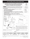
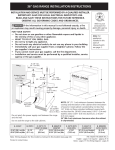
Introduction
really special article that will form part of the history of the brand, of
trial racing and of motorcycling as a sport.
The TR 280i is a motorcycle that has been conceived for competition
and then adapted to traffic regulations for use on public roads. It has
been specifically designed for trial competitions, which means that
its features are ideal for such conditions. It is extremely light in
weight, both its gears and transmission systems and the distribution of its component parts have been arranged with careful
attention and make it a revolutionary machine that is technically
extremely advanced.
* Model without standardisation kit
We at OSSA Motor would like to thank you for purchasing one of our
products.
OSSA motorcycles have been designed, assembled and tested by
experts, and each of its parts has been produced under the supervision of OSSA engineers so as to obtain the best possible results and
the best possible performance.
At OSSA Motor we know that each motorcycle model is unique and
has its own features, which is why we dedicate so much time to the
research and design for each item.
It is very important that you read this User’s Guide to ensure the
correct functioning and maintenance of your new TR 280i.
As the owner of an OSSA motorcycle, you are the member of an
exclusive group. You have just acquired a unique model, the first
model to be produced since the relaunching of OSSA. The TR 280i is
the “visiting card” for our new OSSA Factory. It marks the comeback,
after a 25-year interval, of the legendary brand with the clover logo,
which in the 1960s and 1970s earned itself a solid international
reputation outside the frontiers of the motorcycling world. This is a
User manual
User manual
3
3
Important
Read this manual thoroughly and keep it in a safe place. This manual
provides technical information necessary for keeping your new TR
280i motorcycle in full working condition. It provides information
on common aspects for the motorcycle’s upkeep and fine tuning. In
the event of questions or queries on aspects not mentioned in this
manual, you should consult the OSSA official distributor or a specialist engineer.
Follow each stage of the instructions provided below for obtaining
good results.
These instructions are accompanied by icons to make reading
quicker and easier.
ATTENTION – This symbol indicates that special attention
must be paid!
INFORMATION – Informative note, advice.
Some of the indications specified in this manual are to prevent
possible harm from being inflicted on people or material. Not
following the instructions may result in serious consequences,
which could put people’s lives at risk.
This manual has been put together with the OSSA TR280i current
layout. However, OSSA Motor reserves the right to make changes to
this layout without prior notification to consumers. In the event of
4
User Manual
4 User manual
this taking place, your dealer will provide you with the relevant
information.
- This motorcycle has been designed to carry one
person only. Never ride with passengers!
- Do not carry loads.
- Any additional weight could destabilise the motorcycle which may provoke accidents that incur serious
injury or even death.
Safety
Both your safety and the safety of others are very important when
riding a motorcycle.
Some important advice for using your motorcycle correctly is
detailed below.
- Always drive in a responsible way.
- Always use a helmet.
- Never drive over the speed limit.
- do not ride with passengers.
- This motorcycle is designed to be used in both urban and rural
areas. It should be used, however, while respecting other people
and the environment. If, in your geographical area, the use of motorcycles in rural areas is restricted, you must respect the law.
- Never drive if you have consumed alcohol or any type of substance
(medication, drugs) that might affect your driving capability.
- Make sure your motorcycle is serviced regularly to avoid breakdowns while driving.
- Do not clean the motorcycle with pressurized-water equipment,
since this may damage the parts.
- Do not use your motorcycle for transporting or towing loads. In the
event of needing to carry loads, make sure that they are
light-weight and small in volume so that driving is not affected.
Ensure that there are no loose leads or other elements that might
get caught inside a mechanism. Never apply additional weight to
the handlebars, fork or mudguards. Be especially careful when
transporting any type of load.
- Always wear appropriate clothing and protective accessories.
Gloves, boots and thick trousers, among others, are recommendable. Do not wear baggy clothing that might get caught on a mechanism in the motorcycle.
- Be careful with the exhaust system! The exhaust system gets
extremely hot during and after use of the motorcycle. In the event of
suffering burns, see a doctor as soon as possible.
- Take the time necessary to become familiar with your new motorcycle.
User manual
User manual
5
5
6 User manual
Contents
Introduction
Important warning
Safety
Contents
Technical specifications
Recommendations
3
4
5
7
8-9
10
Section 1 - Components
Location
Multi-function box
Control pad
Front suspension
Readjustment
Air bleed
Rear suspension
Readjustment
Air bleed
Anti-theft immobilizer
Start lever
Fuel tank
Upper engine cover
11
12-14
15-22
23
25
25
26
27
28
29
Section 2 – Maintenance and basic operations
Maintenance grid
Adjustments to the motorcycle controls
Electric connections
Air filter
Radiator
Spark plug
31
32-33
34
35
36
37
38
24
24
Chain
Tension adjustments
Lubrication of moving parts
Tyres
Pressure and condition
Control of crankcase oil
Filling up and draining
Brakes
Torque wrenches
Storage
Troubleshooting
Registration, series number and key
Warranty conditions
Final considerations
39
40-42
43
44
45
46
47
48-52
54-58
59-66
67
User manual
User manual
7
7
Technical specifications
ENGINE
Cubic capacity
Type
Cooling system
Diameter x stroke
Power supply
Ignition
Clutch
272.2 cc
Mono-cylindrical two inverted speeds with admission via slats directly to the sump
Liquid
70x60 mm
EFI Kokusan Battery-less System
CDI Kokusan digital magnetic steering
Hydraulic clutch knob
TRANSMISSION
Gear box
Transmission
Engine lubrication
Changing lubrication and clutch
6 speeds
Primary by gears, secondary by chain
Mix 0.9% Oil 100% synthetic
350 cc. of oil – type Gear Extreme 75 W
CHASSIS
Type
Tube form in CR-MO steel, with pipe and lower part made from forged aluminium
Front suspension
Fork with aluminium bars, 40 mm diameter Marzocchi adjustable in extension and compression
Rear suspension
Variable progressive system with TTX OHlins mono shock absorber adjustable in extension and compression
Front brake
185 mm diameter disc with 4-piston brake caliper
Rear brake
150 mm diameter disc with 2-piston brake caliper
Front wheel
28 spokes with 2.75x21 wheel
Rear wheel
28 spokes with 4.00 x 18 tubeless wheel
Engine protector
Constructed in AA7075 T6
Kick-start pedal
Forged aluminium
Transmission and brake pedal
Forged aluminium with retractable toe cap
8
User manual
8 User manual
Technical specifications
WEIGHTS AND MEASUREMENTS
Distance between axles
Seat height
Distance to the ground
Fuel tank capacity
Mass in service
1.328 mm
655 mm
340 mm
2,6 litres
64 kg
OSSA Factory reserves the right to make modifications without prior notification. Kokusan, Marzocchi, OHlins are registered trademarks and their use is licensed.
User manual
User manual
9
9
Recommendations
It is extremely important to follow the recommendations below in order to keep your motorcycle in full working order.
- 12 hours of running-in is recommended to ensure that the engine works correctly and for a long-lasting time period.
- It is important to run the engine for some minutes until it reaches the correct temperature to work correctly.
- The engine lubrication is a mixture of petrol-oil with a 0.9% oil proportion. Always use synthetic oil.
- When the motorcycle is new the oil must be changed for the first time after 5 hours of use and for the second time after x hours of use.
10
User manual
10 User manual
Section 1 - Components
User manual
User manual
11
11
Location of elements
1 Front mudguard
2 OSSA multi-function box
3 Fan and radiator
4 Cylinder
5 Sparkplug
6 Chain guide
7 Front tyre
8 Front fork stanchion
9 Front suspension bar
10 Gear lever
11 Chain
12 Chain slider
13 Rear crown protector
14 Rear tyre
2
9
1
3
8
5
4
10
6
11
14
12
13
7
*Model without standardisation kit
12
User manual
12 User manual
Location of elements
15 Rear break caliper and anti-theft immobilizer
16 Exhaust
17 Kick-start pedal
18 Fuel tank
19 Rear brake disc
20 Swing arm
21 Rear break lever
22 Crankcase protector
23 Front break caliper
24 Front brake disc
18
16
23
15
19
17
20
21
22
24
*Model without standardisation kit
User manual 13
User manual
13
Location of elements
25 Front brake handle
26 Throttle grip
27 Throttle grip mechanism
28 Front brake pump
29 Right fork stanchion regulator
30 OSSA multi-function box
31 Left fork stanchion regulator
32 Clutch pump
33 Lights control pad
34 Clutch handle
35 Headlights
33
26
27
31
25
28
29
35
*Model without standardisation kit
14
User manual
14 User manual
32
30
34
Multi-function box
The OSSA TR280i multi-function box and the indicator lights next
to it provide very useful information at all times.
The multi-function box is a power box system with an LCD screen
controlled by a console with indicator lights, located in the centre of
the handlebars.
The information displayed on the multi-function box includes: the
number of revolutions made by the engine, speed, distance
covered, total distance covered, time, average speed, maximum
speed, environmental temperature, running time and uptime.
This device has an internal memory unit that stores data like total
Km and total running time, even when it is switched off.
Some features may be personalised: the device can measure in
kilometres or miles. The wheel circumference value can also be
changed.
A temperature sensor warns us with a yellow light (1) when the
engine temperature is excessive.
Another sensor provides a warning with a red light (2) when the
rate at which the engine turns is excessive.
OSSA multifunction display
Temperature warning LED
LED warning of
excessive motor rotation
Left button
Right button
Function Select Button
User manual
User manual
15
15
Multi-function box
Technical features
Functions
Symbol
Technical features
Increasess
Accuracy
Current speed
SDP
4 - 399,9 Km/h o M/h
0,1 Km/h o M/h
+/- 0,1%
Tachometer
RPM
0 - 19999 rpm
10 rpm
+/- 0,1%
Tachometer bar
-
0 - 12000 rpm
Variable
+/- 0,1%
Maximum speed
MS
4 - 399,9 Km/h o M/h
0,1 Km/h o M/h
+/- 0,1%
Distance covered
DST
0,0 - 19999 Km / M
0,1 Km/h o M/h
+/- 0,1%
TT
0 - 9999 hours 59 minutes
1 second
+/- 0,1%
Mileage
ODO
0,0 - 999999
1 Km
+/- 0,1%
Uptime
RT
0 - 999 hours 59 minutes
1 minute
+/- 0,1%
ART
0 - 9999 hours 59 minutes
1 minute
+/- 0,1%
00:00:00
12:59:59 - 23:59:59
Each use
+/- 0,1%
LO
1 year's duration approx
Each use
+/- 0,1%
-
0 - 3999 mm
-
Running time
Accumulated uptime
Clock
Battery low
Tyre size
Input voltage: 9-400 V CA/CC.
Speed sensor: magnetic non-contact sensor
Tachometer input: electrical pulse sensor
Wheel circumference adjuster: 1 mm -3.999 mm (increases of 1 mm)
Running temperature / storage: from 0ºC to 60ºC (from 32ºF to 140ºF) / from -20ºC to 80ºC (from - 4ºF to 176ºF)
Battery / Life: 3V CR2032 / 1 year approx
16
User manual
16 User manual
-
Multi-function
Functions
RPM: Bar
Bar graph tachometer. The tachometer bar graph displays up to
12,000 rpm.
RPM: Digital tachometer
The RPM appear on the right side, on the second line. The digital
tachometer displays up to 12,000 rpm. The tachometer signal can
be captured from the sparkplug wire.
Warning of gear change due to rpm.
The rpm appear on the right side, on the second line. The digital
tachometer displays up to 12,000 rpm. The tachometer signal is
received from the sparkplug wire.
SPD: Speedometer
The speedometer information appears on the centre of the screen.
It displays up to 399.9 km/hour or miles/hour.
MS: Maximum speed meter
It displays the maximum speed reached during the last operation
after having set the counter at zero.
DST: Distance covered
It appears on the right side, on the second line of the screen. The
TRIP function records the mileage accumulated by the vehicle
since the last RESET.
ODO: Mileage counter
It records the distance or total accumulated mileage for the vehicle.
The data is stored in the memory, even when the device is switched
off.
ART: Running time controller
It calculates the total running time. It begins counting as soon as
the engine is switched on.
RT: Total running time controller
It calculates the vehicle’s running time from the last RESET. It
begins to count from when the vehicle starts to move. The data is
stored in the memory, even when the device is switched off.
12/24 hour clock
It displays the current time in 12 or 24 hour clock. It indicates the
temperature of the environment and engine. The display screen on
the upper left shows the environmental temperature. Using an
optional temperature sensor, the screen displays the engine
temperature. If excessive, the yellow light comes on.
Indicator that engine turn rate is excessive / Warning of gear change
due to rpm.
If the engine turn rate is excessive a second red warning light will
come on. This function acts as a warning to change gear when a
specific number of rpm is reached. The red light flashes when the
rpm reaches the established value and stops flashing when the
gear is changed.
User manual
User manual
17
17
Multi-function
Adjustment of the multi-function box settings
After confirming each value, the multi-function box will move straight on to the next screen adjustment until the process is complete. If no
button is pressed, the multi-function box will return to the initial screen after 15 seconds.
Select the speed unit
To select the speed unit
between km/h and m/h, press
1. Confirm your selection by
pressing 2.
Activation of the adjustment mode
To activate the adjustment
mode for the multi-function
box settings, push buttons 1,2
and 3 simultaneously for 3
seconds and then release
them.
1
Select the wheel circumference
Enter the wheel circumference by pushing button 1 repeatedly. To move to the next
digit, press button 3. Confirm
the selection by pushing
button 2. Note: If you don’t
know the wheel circumference, consult the “Measuring
the wheel circumference”
section.
18
User manual
18 User manual
2
3
1
2
1
2
Select the time format
To select the time format
change between the 12 and
24, press 1. Confirm your
selection by pressing 2.
1
2
3
Multi-function
Time adjuster
Set the time by pressing
button 1 repeatedly. To move
to the next digit, press button
3. Confirm the selection by
pushing button 2.
1
Adjustment of the revolution pulse
(PPR)
Note:
This step must only be
followed for those vehicles
that change the PPR pulse
type to a specific turn rate. If
you don't know this value,
press button 2 to move on to
the next screen. Enter the
value by pressing button 1
repeatedly. To move on to the
next digit, press button 3.
Confirm the selection by
pushing button 2.
2
Adjustment of the revolution pulse
(PPR)
The indicator receives an
electric pulse each time the
engine turns (PPR). Default
value for 2 and 4 stroke
engines:
1 PPR. Enter the value by
pressing button 1 repeatedly.
To move on to the next digit,
press button 3. Confirm the
selection by pushing button 2.
Adjustment of the revolution pulse
(PPR)
Note:
This stage must only be
implemented if in the
previous stage the value 0
was entered.
Default value: 1.0. If you don’t
know this value press button
2 to move on to the next
screen. To move on to the
next digit, press button 3.
Confirm the selection by
pressing button 2.
1
2
3
1
2
3
User manual
User manual
19
19
Multi-function
Temperature selector
Warning temperature selector
Note:
To select the unit of temperature,
either ºC or ºF, press button 1.
Confirm the selection by
pressing button 2.
1
2
3
Danger temperature selector
Note:
This stage should only be
implemented for those vehicles
that have an optional temperature sensor. When the motorcycle
temperature exceeds the set
value, right-hand warning light
comes on.Default value: 110ºC
(230ºF).
Enter the value by pressing
button 1 repeatedly. To move on
to the next digit, press button 3.
Confirm the selection by
pressing button 2.
20
User manual
20 User manual
This stage should only be
implemented for those vehicles
that have an optional temperature sensor. When the motorcycle
temperature exceeds the set
value, the left-hand warning light
comes on.
Default value: 90ºC (190ºF).
Enter the value by pressing
button 1 repeatedly. To move on
to the next digit, press button 3.
Confirm the selection by
pressing button 2.
1
2
3
1
2
3
Gear change turn rate selector
1
2
3
When the set rate is near to
being reached, the left-hand
warning light will flash, indicating
the need to change gear.
Default value: 6000 rpm
Enter the value by pressing
button 1 repeatedly. To move on
to the next digit, press button 3.
Confirm the selection by
pressing button 2.
Multi-function
Dangerous turn rate selector
When the set rate is near to
being reached, the right-hand
warning light will flash, indicating that the engine is turning
at an excessive rate.
Default value: 10,000 rpm
Enter the value by pressing
button 1 repeatedly. To move
on to the next digit, press
button 3. Confirm theselection by pressing button
2.
Setting the whole multi-function box to zero
Press the RESET button by using a suitable object. The indicator will
boot again, excluding data that corresponds to total accumulated
distance and time.
CLOSE
OPEN
1
2
3
RESET
BATTER
CR
2032 Y
POSITIVE
RESET
BATTERY CR2030
2
3
Setting the indicator functions to zero after each use of the vehicle
After each use of the vehicle, it’s possible to set the following
functions to zero, simultaneously:
- Maximum speed
- Distance
- Chronometer
- Maximum temperature
- Maximum turn rate
Confirm that you want to set these functions to zero by simultaneously pressing buttons 1 and 2.
Internal battery
The multi-function box works with a 3V internal battery, type
CR2032. When the battery tension falls beneath 2.45V, the screen
displays the LO indicator. To change the battery, open the lid on the
bottom of the indicator by unscrewing it as is indicated in the image,
using a coin. Ensure that the positive side of the battery is facing
upwards.
User manual
User manual
21
21
Multi-funcition
Screen Options
The multi-function box displays all information on three different screens.
While on, it is possible to see screens 1 or 2. Screen 3 is displayed for
three seconds and then returns to screen 1.
To move from one screen to another repeatedly press button 2 (“Mode”).
To edit the distance covered (DST) hold down button 3.
Screen 1:
Screen 1 displays the following information:
- Speed, distance covered, time, environmental temperature, tachometer
(bar).
Screen 2:
Screen 2 displays the following information:
- Speed, digital tachometer, running time, uptime, engine temperature*,
tachometer (bar).
Pantalla 3:
Screen 3 displays the following information:
- Maximum speed, dangerous turn rate, accumulated running time,
mileage counter, maximum temperature*.
* optional
Screen illumination
The multi-function box works by using a 3V internal battery, type CR2032.
To change the battery, open the lid on the bottom of the indicator by
unscrewing it, as indicated in the image, using a coin. Ensure that the
positive side of the battery is facing upwards.
When the multi-function box is powered exclusively by the internal battery,
the screen illumination is partially maintained for 3 seconds when the
button is pressed.
When it is connected to the 12V vehicle installation, the illumination will
22
User manual
22 User manual
be brighter and will remain constant for 20 minutes after the vehicle has
stopped.
Sleep Mode
If the multi-function box receives no information for 20 minutes (wheel
signal, turn signal or pressed button) the screen will turn off, displaying
only the time. When the vehicle moves, or by pressing any button, it will
start up again.
Measuring the wheel circumference
Method 1:
Measure the diameter of the front wheel. Multiply the diameter obtained
by 3.14. If necessary, convert the measurement into mm by multiplying
the obtained figure by 25.4. The measurement obtained corresponds to
the measurement of the wheel circumference.
Method 2:
On a smooth and flat surface, put a mark on the side of the tyre and in the
area where it is touching the ground. Move forward with the vehicle until
the wheel has tuned completely once and the mark is on the lowest part
again. Put a new mark on the ground at this point. Measure the distance
between the two marks on the ground. If necessary, convert the measurement in mm by multiplying the figure obtained by 25.4. The measurement obtained corresponds to the wheel circumference. To obtain a more
accurate measurement, the rider should remain on the vehicle when the
measurement is taken.
Control Pad
Control Pad
The control pad is located on the left handlebar, within reach of the
thumb. This control pad can be used to control the lights, indicators, horn and engine stop.
6
1
2
3
4
3
2
1
See the image with information about the control pad.
5
4
See the image with information about the control pad.
1 – Pilot lamp for change of direction (left – right)
2 – Pilot lamp for cross lights
3 – Pilot lamp for long range lights
4 – Pilot lamp for footrest
1 – Position lights
2 – Cross lights
3 - Long range lights
4 – Lights for changing direction (left – right)
5 – Horn
6 – Button to switch off engine
User manual
User manual
23
23
Front suspension
The front suspension is made up of a fork that fixes the wheel and
the front brake system in place. This fork is formed by the suspension bars that contain the shock absorber spring and the suspension
mechanism. They are connected to the upper part where the
direction pipe is located, a point of connection between the fork
and the chassis. A regulating screw and an air bleed are located on
the upper part of each suspension bar (see photo).
To regulate the extension, use the screw located on the right
suspension bar (Fig. A)
To regulate the compression use the screw located on the left
suspension bar (Fig. B)
Each of the suspension bars also has an air bleed to remove air that
accumulates in the inside of the fork stanchion (Fig. C)
B
A
C
24
User manual
24 User manual
C
Rear suspension
The rear suspension is formed by a single shock absorber spring. The
pre-charge of this spring can be adjusted by turning the toothed
rings that dictate its direction.
A special key is needed to adjust these toothed rings.
The compression (C), extension (R) and spring pre-charge (see Fig.)
are adjustable in the rear shock absorber.
C
R
Adjustable rings for the spring pre-charge
User manual
User manual
25
25
Anti-theft immobilizer
The TR280i has an immobilisation system for protection against
theft.
This system consists of a lock situated in the area of the brake discs
on the rear wheel. It is a mechanism that is operated with a key and
blocks the rear wheel.
26
User manual
26 User manual
IMPORTANT: this key has a code which is needed for
making duplicate copies of the key. This code should be
written down in the indicated space on the registration
page and series number of this manual.
Kick start pedal
The kick-start pedal is part of the mechanism that is used to kick
start the motorcycle mechanically.
Before kick starting the motorcycle check that it is at brake point
(neutral). DO NOT try to kick start the motorcycle when it is in gear.
To kick start the motorcycle, the kick-start pedal must be separated
from the bike and moved outwards. Once separated, place your foot
on top and push strongly in a downwards direction with a kicking
motion.
If the motorcycle has been inactive for a long period of
time, its recommended that the kick-start pedal is activated gently 3 or 4 times, without actually kick-starting the
motorcycle. This will enable the engine to move which will
help when kick-starting it.
If the motorcycle has been inactive for a very long period
of time, change the oil and petrol because they might
have become degraded. This could affect the motorcycle's
performance.
User manual
User manual
27
27
Fuel tank
The engine of this motorcycle uses a mixture of
unleaded petrol and 2T oil, 100% synthetic in a 0.9
proportion.
The fuel tank forms a structural part of the chassis and
is located on the front inside part. To fill up with petrol,
open the fuel tank lid, situated on the upper part, by
unscrewing in an anti-clockwise direction.
It’s recommended that a hose or funnel is used to fill
up to avoid spilling the petrol. This is especially
important if the motorcycle is hot. DO NOT fill up
with petrol when the motorcycle is turned on.
28
User manual
28 User manual
Upper Section
To access different parts of the motorcycle or the motorcycle’s
electrical system the upper section should be removed. This section
is made up of 2 parts that are screwed onto the chassis and fitted
together.
The first part of this section is located on the front above the fuel
tank. Next is the second part of this section which corresponds to
the seat area and rear mudguards.
1
2
Remove the upper section. Stage 1
* Model without standardisation kit
Remove the upper section. Stage 2
User manual
User manual
29
29
30
User manual
30 User manual
Section 2 – Maintenance and basic operations
User manual
User manual
31
31
Maintenance grid – Engine
Item
Check / Inspect
Adjust
Replace / Change
Clean
Grease / lubricate
Air filter
Each use
_
When damaged
Each use
Each wash
Transmission oil
30 Hours
_
60 horas
_
_
Refrigerant
Each use
_
Each year
_
_
Sparkplug
Each use
30 Hours
60 Hours
15 Hours
_
Reed block
30 Hours
When necessary
When damaged
_
_
Cylinder
60 Hours
_
Each year
_
_
Clutch
Each use
_
When damaged
_
_
_
_
When damaged
_
_
Exhaust
Each use
_
When damaged
_
_
Silencer
_
_
When damaged
_
_
Wire and throttle grip
Each use
When necessary
When damaged
When necessary
Each wash
Change / kick-start pedal
Each use
When necessary
When damaged
When necessary
Each wash
Piston and piston ring
60 Hours
_
Each year
_
_
Radiator tube and connections
Each use
When necessary
_
_
_
Clutch discs
32
User manual
32 User manual
Maintenance grid – Cycle
Item
Check / Inspect
Adjust
Replace / Change
Rear shock absorber
Each year
_
Every 2 years
_
_
Front suspension
Each year
When necessary
Every 2 years
_
_
_
_
60 Hours
_
_
Brakes
Each use
When necessary
When damaged
_
_
Swing arm and linkage arms
Each use
_
When damaged
Each use
Each wash
Secondary transmission
Each use
When necessary
When damaged
Each use
Each wash
Steering bearings
Each use
_
When damaged
_
Each wash
Wheel bearings
30 horas
_
When damaged
_
Each wash
Brake discs
Each use
When necessary
When damaged
_
_
Tyres
Each use
_
When damaged
_
_
Front/rear tyre
Each use
_
When damaged
Each use
_
Front/rear spokes
Each use
5 Hours
When damaged
Each use
_
Chassis
Each use
_
When damaged
Each use
_
Fuel tank
Each use
_
When damaged
Each use
_
Screw, nuts and fastenings
Each use
When necessary
When damaged
Each use
_
_
First use
When damaged
Each use
_
Each use
_
When damaged
_
_
Front suspension lubricant
Crankcase protector
Protective stickers
Clean
Grease / lubricate
User manual
User manual
33
33
Adjustments to the motorcycle controls
The clutch lever is located on the left handlebar grip and is used to activate the clutch mechanism to change gear.
The front brake lever is located on the right handlebar grip and is used to activate the brake caliper of the front brake.
min. 3 mm
Front brake lever
Clutch lever
min. 3 mm
It’s important that the levers and rear brake pedal have a 2-3 mm give.
It’s important that the levers can be easily activated by the rider while he/she is riding the bike, using the index and middle fingers.
34
User manual
34 User manual
Electrical connections
Check the condition of the motorcycle’s electrical connections in
order to ensure they are maintained in good working order.
As can be seen in the illustration on the right, these are located at
the bottom of the air-filter housing, between the steering bar and
the front headlight, and in the fuel system apparatus.
Carry out a regular and thorough maintenance of
your motorcycle. Always use original spare parts
and top quality products to ensure that it works
correctly.
User manual
User manual
35
35
Simplified
diagram of the
lights
Esquema simplificado
instalación
de luces
36
Manual de usuario
36 User manual
Esquema
simplificado
deinstallations
inyección
Simplified
diagram ofinstalación
the injection
Manual de usuario 37
User manual
37
Air filter
Air filter. Cleaning and maintenance
The air filter should be controlled periodically. Detach the upper
section of the motorcycle to reach the filter box. Remove the sensor
on the filter base and the clasp. Then remove the filter, according to
the illustration. To clean, use water and detergent, leave to dry and
then lubricate with a special liquid for filters. Reassemble using the
steps outlined previously but in reverse. Make sure that the parts are
put in their correct positions.
Carry out a regular and thorough maintenance of
your motorcycle. Always use original spare parts and
top quality products to ensure that it works correctly.
36
User manual
38 User manual
Radiator
The radiator contains the engine refrigerant. To fill up with or add
refrigerant to the radiator, locate the tank lid. To locate this lid,
detach the air filter lid (see page 36 - Air Filter). Once the filter lid is
detached, the radiator lid is visible. Unscrew the lid and pour in
refrigerant.
ATTENTION: Use gloves. Do not open the lid if the
engine is hot. This could cause burns. Avoid contact of
the liquid with the eyes, mouth or nasal passage. Do
not ingest. In the event of this happening, follow the
product instructions and consult a doctor.
To fill the radiator, special refrigerant should be used -30ºC.
To ensure that the motorcycle works correctly, periodic controls
must be carried out to check the refrigerant levels. This will ensure
that the motorcycle is running at an optimum temperature.
Always use special refrigerant for light alloy engines.
The radiator has an electric fan to force air through it, as can be seen
in the image below.
User manual
User manual
37
39
Sparkplug
To access the sparkplug detach the upper section of the motorcycle (see page 29). Once the upper cover has been removed, the
motorcycle’s electrical system can be accessed. Carefully but
firmly, pull away the hood that provides a current, leaving the upper
part of the sparkplug exposed. Using a special sparkplug key,
unscrew it.
The sparkplug should be checked regularly and a spare
sparkplug should be carried at all times in case it comes
off. The sparkplug can accumulate charcoal and dirt with
use. For this reason, it can be removed and cleaned so
that it lasts longer.
Observe the distance between the electrode and the
arch. This distance should be 0.7 mm.
0,7 mm
NOTE: The sparkplug should not be handled if the
motorcycle is hot.
38
User manual
40 User manual
Chain – tension adjustments
The transmission chain transmits the engine’s movement to the rear
wheel. To ensure that is works correctly, it should be checked.
The axle has easily adjustable eccentrics for tensing
the chain and centring the wheel.
The chain hook should be positioned in an opposite
direction to the gear, as can be seen in the photo.
The chain tension should permit 2 cm of oscillation
in the chain tension adjuster.
User manual 39
User manual
41
Lubrication of moving parts
Cleaning the motorcycle and lubricating the mobile parts will help
protect the motorcycle and guarantee that it works better.
If using a high pressure hose to clean the motorcycle, bear
in mind that the water pressure might rip off the stickers
or cause damage to the motorcycle. To prevent this, hold
the hose at a distance of 30-40 cm from the motorcycle
and take extra care on delicate parts.
Lubricate using specific products:
1.Transmission chain
2.Clutch and brake lever joints
3.Gear lever joints
4.Rear brake pedal joints and bearings
5.Footrest brackets and springs
6.Engine kick-start pedal joints
7.Gas handle (right grip)
Use specific lubricants for each part of the motorcycle.
Take care NOT to accidentally lubricate the brake
caliper or brake pads. If this happens clean off the
lubricant and carry out controlled braking until the
brakes work correctly again.
40
User manual
42 User manual
Clutch and brake lever joints
Lubrication of moving parts
The chain drive should always be well lubricated.
Check it each time the motorcycle is used and apply
lubrication when necessary.
Chain drive
The chain must be lubricated using special oil for chain
drives.
Gear change lever joints
Rear brake pedal joints and bearings
User manual
41
User manual
43
Lubrication of moving parts
Footrest bracket and springs
Chain drive and tension adjuster springs
Engine kick-start pedal joints
42
User manual
44 User manual
Gas handle (right grip)
Tyres
Pressure and condition
To ensure that the motorcycle works correctly, it’s very important to
check the tyre pressure and that the wheels are in good working
condition before each use. Using tyres that are in a good condition
will mean that the motorcycle is capable of performing to the best
of its ability. It also ensures that trial riding is safer and more
efficient.
Front tyre:
2.75x21”
Tyre in good working condition
Rear tyre:
4.00x18”
Front tyre pressure:
0.45 bar - normal
0.42 bar - competition
Rear tyre pressure:
0.35 bar - normal
0.30 bar - competition
Tyre in bad working condition
NEVER forget to periodically check the tyre pressure
to ensure that the tyres have a good grip
User manual
43
User manual
45
Checking the crankcase oil
IMPORTANT: Clean the plug and change the sealing washer each
time the oil is changed.
Filling and draining the crankcase
Crankcase oil is used for lubricating the change pedal and the
clutch. Check the oil level with the indicator located on the lower
part of the clutch cover, which is on the right side of the engine. The
oil level should be lower than the indicated maximum level.
MAX.
The crankcase has a 350cc oil capacity. 2T 100% synthetic
oil should always be used.
Optimum oil level
(A)
MIN.
Clutch cover (D)
The oil level should be checked when the motorcycle is in an upright position and on a flat surface. The
motorcycle should be cold. If it is not cold, wait some
minutes until it goes cold.
To add oil, remove the cap (A) located on the top of the
clutch cover (D). Use a funnel to add the oil, NEVER filling
above the Maximum level. Replace the cap. If you fill
above the Maximum level, oil must be removed. To
remove oil from the hood, place a receptacle under the
motorcycle and remove the lid (B) located on the side of
the hood, leaning the bike over in both directions to
ensure that no oil remains inside the hood.
44
User manual
46 User manual
Indicador
Ignition cover (C)
(B)
Brakes
The brakes permit precise and controlled trial riding. It is necessary
to check them in order to ensure that they work correctly.
Wear on the front and rear brake pads must be
periodically controlled so that the brakes work
effectively.
The oil level can be checked using the indicator on
the front handle and on the rear pump tank. The oil
level should be situated between the min and max
values.
MAX.
MIN.
To remove surplus air from the break circuit, the
calipers are equipped with air bleeds. See image.
User manual
User manual
45
47
Torque wrenches
These grids show the pressure that should be used to tighten parts.
CHASSIS
46
MOTOR
Part
N-m
Part
Front wheel axle
40 - 50
Sparkplug
Swing arm fixing to chassis
70 - 80
Clutch fixing
7-8
Upper shock absorber fixing
40 - 50
Cylinder clasp fixing
7-8
Lower shock absorber fixing
40 - 50
Cylinder reed fixing
25
Linkage arm fixing
40 - 50
Pressure plate fixing
7-8
Handles
18 - 25
Clutch mass fixing
3-4
Handlebar
7 - 10
Crankcase half fixing
7-8
Radiator fixing
7 - 10
Water pump cover fixing
7-8
Front wing bridge section
7 - 10
Clutch cover fixing
7-8
Break pedal
27 - 32
Steering fixing
40
Silencer fixing
18 - 25
Water separator
10
Rear wheel axle
80 - 90
Ignition cover
Rear brake caliper fixing
27 - 32
Engine drain plug
Front brake caliper fixing
27 - 32
Kick-start pedal screw
Exhaust pipe fixing
27 - 32
Transmission pedal screw
7-8
Engine fixing
18 - 25
Cylinder block screws
8-9
Rear brake pump fixing
7 - 10
Cylinder nuts
User manual
48 User manual
N-m
11
7-8
12
12 - 13
25
Storage
Storage
Starting the motorcycle again
If the motorcycle is to be stored for a long period of time, the
following procedure should be followed to ensure that it is stored
correctly.
- Clean the motorcycle as much as possible because dirt
can cause the deterioration of components.
-Turn on the engine for a few minutes to warm up the
transmission fluid and then drain. (see section on draining fluid).
-Fill up with new transmission fluid.
-Empty the fuel tank (petrol degrades over time).
-Lubricate the chain and all wires.
-Apply oil to non-painted metal surfaces to prevent rust.
Avoid putting oil on the brakes and rubber parts.
-Wrap the outside of the exhaust pipe in a plastic bag to
prevent rust.
-Position the motorcycle so that the wheels don’t touch the
ground to prevent possible tyre deformation. If this is not possible,
cardboard can be placed underneath the wheels.
-Place a cover over the motorcycle such as canvas, plastic
or material. This will protect the motorcycle from dust and other
external factors. Avoid storing the motorcycle outside, or in direct
sunlight.
To start up the motorcycle after a period of inactivity, the following
procedure should be followed:
-Remove the plastic covers that were placed over the
motorcycle before storing, including the exhaust pipe and those
parts that had special protection.
-Tighten the sparkplug.
-Fill up the fuel tank with new petrol.
-Carry out general lubrication.
-Check tyre pressure.
-Leave the engine running for some minutes to warm up
the engine oil.
User manual
User manual
47
49
Troubleshooting
PROBLEM
POSSIBLE CAUSE
The engine won’t start
POSSIBLE SOLUTION
- Long period of engine inactivity
- Change the old petrol for new petrol
- Sparkplug dirty or wet
- Dry / clean or change the sparkplug
- General fuse damaged
- Change general fuse
- Bad electrical connection
- Check electrical connections and position correctly
- Take the motorcycle to a specialist mechanic
The engine starts and then stops
- Lack or deterioration of petrol
- Fill the fuel tank with new petrol
- Take the motorcycle to a specialist mechanic.
In the event of breakdown always take the motorcycle to a specialist mechanic
48
User manual
50 User manual
Troubleshooting
PROBLEM
POSSIBLE CAUSE
The motorcycle is unstable
The shock absorption is too hard
POSSIBLE SOLUTION
- Wire makes it difficult for the handlebar
to turn
- Move wire or loosen it a bit
- Steer axle screw is very tight
- Steering bearings are damaged or with
wear
- Loosen the steer axle screw
- Replace steering bearings
- Steer axle bent
- Change the steer axle. Contact an officially registered
mechanic.
- Excessive oil on front fork
- Oil too viscous on front fork
- Front fork bent
- Remove surplus oil until it reaches the correct level.
- Drain fork oil and fill up with viscous oil.
- Change the front fork. Contact an officially registered
mechanic.
- Check the pressure of the tyres
- Adjust the rear shock absorber
- Tyre pressure too great
- Rear shock absorber badly adjusted
In the event of breakdown always take the motorcycle to a specialist mechanic
User manual
User manual
49
51
Troubleshooting
PROBLEM
POSSIBLE CAUSE
The shock absorption is too soft
POSSIBLE SOLUTION
- Too little oil in front fork
- Add oil to the fork until it reaches a sufficient level
- Front fork oil not sufficiently viscous
- Drain fork oil and fill up with suitably viscous oil
- Front fork bent
- Change the front fork. Contact an officially registered
- Rear shock absorber badly adjusted
- Adjust the rear shock absorber
- Chain badly adjusted
- Adjust chain
- Chain wear
- Change chain, rear crown and secondary transmission pinion
- Rear crow teeth wear
- Change rear crown
- Insufficient chain lubrication
- Lubricate chain
- Rear wheel badly adjusted
- Align rear wheel. Contact an officially registered mechanic.
- Front fork with insufficient oil
- Add oil to the fork until it reaches a sufficient level.
- Front fork spring weak or broken
- Replace front fork spring
- Brake disc wear
- Replace brake disc
- Brake pads badly positioned or
- Change position of break pads or replace them.
mechanic.
The motorcycle makes abnormal
noises
crystallised
In the event of breakdown always take the motorcycle to a specialist mechanic
50
User manual
52 User manual
Troubleshooting
PROBLEM
POSSIBLE CAUSE
The motorcycle makes abnormal
noises
POSSIBLE SOLUTION
- Cylinder damaged
- Replace the damaged cylinder
- Supports, screws or nuts are not properly
- Check and adjust using suitable torque wrench
fastened
- Tyres wear, swing arm or its needle
- Change worn parts for new parts
bearings wear
The handlebar vibrates
- Wheel rim not centred
- Centre wheel rim
- Wheel not centred
- Check the tension of the spokes and readjust
- Lack of engine oil
- Check and add engine oil
- Steer axle with excessive tolerance
- Tighten the handlebar support and the steer axle nut
- Handlebar support loose, steer axle nut
- Tighten the handlebar support and the steer axle nut
using suitable torque wrenches.
loose
using suitable torque wrenches.
In the event of breakdown always take the motorcycle to a specialist mechanic
User manual
User manual
51
53
Troubleshooting
PROBLEM
POSSIBLE CAUSE
The motorcycle tends to lean to one
side
The brakes don’t work correctly
POSSIBLE SOLUTION
- Bent chassis
- Change chassis. Go to specialist mechanic
- Steering badly adjusted
- Adjust steering. Go to specialist mechanic
- Steer axle bent
- Change steering axle. Go to specialist mechanic
- Front fork bent
- Change front fork
- Wheels badly centred
- Align wheels
- Disc wear
- Change disc
- Loss of brake fluid
- Check brake circuits. Change if damaged or broken
- Brake fluid in bad condition
- Drain brake fluid and replace with new fluid recommended
by a mechanic
- Pump piston broken
- Replace the pump piston
- Brakes badly adjusted
- Adjust brakes
In the event of breakdown always take the motorcycle to a specialist mechanic
52
User manual
54 User manual
Elementos de homologación
Manual de usuario
User manual
53
55
Standardisation components
Your Ossa TR280i is standardised in compliance with UE regulations. It adheres to all standardisation requisites. EURO-3
The obligatory elements to be registered for driving on public roads and for passing the vehicle’s MOT are listed below.
The elements to be registered among others are identified with a specific mark and registration.
Each of the registered elements should be part of the vehicle. In the event of breakages, loss or bad functioning, it is recommended that you go to an official OSSA mechanic to remedy the problem.
54
User manual
56 User manual
Standardisation components
10
7
13
3
4
5
6
1
11
1.Front headlight
2.Front indicators
3.Rear indicators
4.Rear pilot
5.License plate support
6.Reflector
7.Mirrors
8.Manufacturer’s plate
12
2
14
9
8
15
9.Exhaust system
10.Speedometer
11.Pinion output
12.Lock
13.Horn
14.Kickstand
15.Gas stop
Each of the registered elements should be part of the vehicle. In the event of breakages, loss or bad
functioning, it is recommended that you go to an official OSSA mechanic to remedy the problem.
User manual
User manual
55
57
Standardisation components
Element
Standardisation identification
1. Front headlight
Front position lamp
Driving beam
Passing Beam
2. Front indicators
3. Rear indicators
4. Rear pilot
5. License plate support
6. Reflector
7. Mirror
8. Manufacturer plaque
9. Exhaust system
10. Speedometer
11. Pinion output
12. Lock
13. Horn
14. Kickstand
11/12-e9*97/24*97/24/*4367*00
R55.00.14839
R113.00.14839
R113.00.14839
11001200e94367
11001200e94367
e13*50 R00*50R00*12448*00
56
User manual
58 User manual
IA.E9.02.01269
L-e9*80/780*80/780*0143*01
z=11
e13*28R00*28R00*0037*00
Standardisation components
Manufacturer’s plate
Serial number
User manual
User manual
57
59
Standardisation components
The key number can be found under the red disk.
Remove the disk to see the number.
Engine number
58
User manual
60 User manual
Key number
Warranty
User manual
User manual
59
61
Warranty
Terms and conditions of the warranty
The warranty is associated to the product indicated in the “CERTIFICATE OF DELIVERY AND INSPECTION”, which shall be filed out by authorised staff in OSSA FACTORY, SL (hereinafter referred to as OSSA). It is valid for those countries indicated on page 33. The warranty is only
applicable to motorcycles that have been initially imported via the official OSSA importer for your country, meeting all the regulatory requirements and authorisations of each country. This warranty does not limit or adversely affect consumers’ legal rights and guarantees by virtue
of any obligatory national regulations. It is independent of the legal warranty provided by the official dealer.
Name and address of guarantor
The guarantor is the commercial organisation OSSA FACTORY, SL, Crta. Antiga d’Amer, nave 12, Pol. Ind. Domeny, 17150 Domeny (Girona),
Spain.
Consumer’s rights as warranty holder
With this document OSSA provides the final user with a guarantee that the motorcycle manufactured by OSSA is free from defects and that
it has been manufactured in compliance with the strictest quality control regulations. Therefore, the warranty extends to both the parts and
the labour costs in the event of any repair provoked by faulty materials or manufacture detected in a new motorcycle. This is applicable for
the time period stipulated within the warranty without limitation, except for those that are listed in this manual. The maintenance and service
requirements indicated by OSSA must have been adhered to, in compliance with the conditions herewith, for the warranty to be valid.
OSSA is held responsible before the purchaser in the event of the product’s non-compliance at the time of product delivery. When the product
is non-conforming, the purchaser must decide whether they want the product to be repaired or replaced. The purchaser’s decision, when
notified to the seller, is binding for both parties with one sole exception: if the cost of reparation or replacement is disproportionate to the
product’s value, the most reasonable solution will be taken into account. Rectification considered as disproportionate is that which implies
costs for the seller which are not reasonable in contrast with the other means of rectification. This takes into account the value the product
would have if the non-compliance did not exist, as well as the relevance of the non-compliance and if the alternative means of rectification
could be carried out without any inconvenience.
60
User manual
62 User manual
Warranty
The repair is disproportionate when it is uneconomic, or when the reparation is more expensive than the value of the product. If this occurs,
the purchaser can choose between a price reduction or contract resolution. Resolution is not permitted when the non-compliance is insignificant.
Regulations for repairs, product replacement, price reduction or contract resolution:
1.
It will be free for the purchaser.
2.
It will be carried out in a reasonable time period.
3.
In the six months following delivery of the repaired product the seller will be answerable for those faults which necessitated
the repair. When defects occur of the same origin as those initially repaired, it will be presumed that it is the same fault.
4.
If, after the product has been repaired, the product still has faults while the warranty is in force, the purchaser can choose
between a replacement, a price reduction or refund. If the purchaser selected a product replacement, they can request a repair – always
while the cost of this repair is not disproportionate – a price reduction or refund.
5.
The seller is not obliged to replace fungible or second hand goods.
6.
The price reduction will be proportional to the difference between the value that the product would have had on delivery if the
fault did not exist and the value that the product had at the time of delivery.
7.
In the event of it being impossible for the purchaser to address the seller for the product’s non-compliance with the purchase
agreement, they will be allowed to claim directly to the manufacturer in order to obtain a replacement or product repair.
User manual
User manual
61
63
62
User manual
64 User manual
Warranty
Exceptions to the warranty
User manual
User manual
63
65
Warranty
64
User manual
66 User manual
Warranty
User manual
User manual
65
67
Warranty
Procedure for obtaining repairs under warranty
If your motorcycle needs a repair to be carried out under warranty, it should be taken to your official OSSA dealer where the repair will be
made (YOU ARE RESPONSIBLE FOR THE TRANSPORT COSTS TO AND FROM THE DEALER).
Ossa recommends that you go to the dealer where your purchase was made. However, you can go to any Ossa dealer for repairs to be carried
out under guarantee.
This guarantee provides you as a consumer with specific legal rights. You may also have additional consumer rights that vary depending
upon which country you are in.
If one of the afore-mentioned terms is invalid due to regional or federal laws, all other terms stipulated in this warranty continue to be valid.
66 User manual
68
User manual
Final information
User manual
User manual
67
69
70 User manual
User manual
71