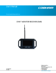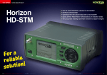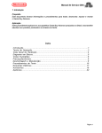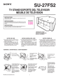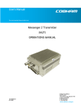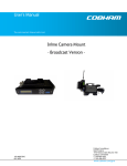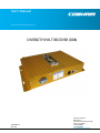
1
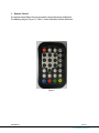
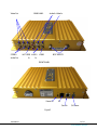
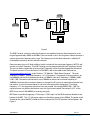
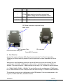
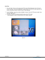
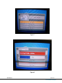
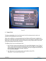
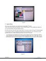
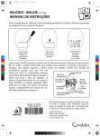
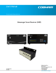
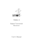
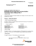
 User’s Manual
The most important thing we build is trust.
DIVERSITY DVB-T RECEIVER (DDR)
100-M0062X2
05/15/09
Cobham Surveillance
GMS Products
1916 Palomar Oaks Way Ste 100
Carlsbad, CA 92008
T: 760-496-0055
F: 760-496-0057
www.cobham.com/gms
TABLE OF CONTENTS
1
2
3
4
5
6
7
8
9
ACRONYMS…………………………………………………………………………………………………………………………..3
INTRODUCTION…………………………………………………………………………………………………………………..4
REMOTE CONTROL………………………………………………………………………………………………………………5
HARDWARE OVERVIEW………………………………………………………………………………………………………6
4.1 Composite Video Out……………………………………………………………………………………………………...6
4.2 Stereo Out……………………………………………………………………………………………………………………….. 8
4.3 Audio In…………………………………………………………………………………………………………………………….8
4.4 Video In…………………………………………………………………………………………………………………………….8
4.5 RF/IF Inputs………………………………………………………………………………………………………………………8
4.6 Data In……………………………………………………………………………………………………………………………….8
4.7 Power On LED…………………………………………………………………………………………………………………...8
4.8 IR Sensor………………………………………………………………………………………………………………………….. 8
4.9 DC Power…………………………………………………………………………………………………………………………..8
USE WITH GMS MDL LINK………………………………………………………………………………………………….8
FIRST TIME USE…………………………………………………………………………………………………………………10
CHANNEL SEARCH……………………………………………………………………………………………………………..11
PROGRAM GUIDE……………………………………………………………………………………………………………….15
SYSTEM SETUP…………………………………………………………………………………………………………………..15
100-M0062X2
2 of 17
www.cobham.com/gms
1
Acronyms
This section lists and describes the various acronyms used in this document.
Name
16QAM
64 QAM
A/V
AES
ABS
ASI
COFDM
CVBS/Y
C
D/C
DDR
FEC
GUI
I/O
Kbaud
Kbps
Mbps
MDL
MDL-B
MDR
MDR-B
MDT
MDT-B
MER
MPEG
NTSC
PAL
QPSK
RF
RX
S/N
THD
SDI
TX
VDC
Meaning
16-state Quadrature Amplitude Modulation
64-state Quadrature Amplitude Modulation
Audio/Video
Advanced Encryption System (32 bit)
Messenger Basic Scrambling (8 bit)
Asynchronous Serial Interface
Coded Orthogonal Frequency Division Multiplexing
Composite video/Luminance with S-video
Chroma video
Down-Converter
Diversity DVB-T Receiver
Forward Error Correction
Graphical User Interface
Input/ Output
Kilobaud per second
Kilobits per second
Megabits per second
Messenger Digital Link
Messenger Digital Link, Broadcast Version
Messenger Digital Receiver
Messenger Digital Receiver, Broadcast Version
Messenger Digital Transmitter
Messenger Digital Transmitter, Broadcast Version
Modulation Error Rate
Moving Picture Experts Group
National Television System Committee
Phase Alternation Line
Quadrature Phase Shift Keying
Radio Frequency
Receiver
Signal-to-Noise Ratio
Total Harmonic Distortion
Serial Digital Interface
Transmitter
Volts (Direct Current)
100-M0062X2
3 of 17
www.cobham.com/gms
2
Introduction
The GMS Diversity DVB-T Receiver (DDR) is a commercial VHF/UHF terrestrial receiver designed for the
European market, which can be used in a GMS Messenger Digital Link (MDL). This MDL link includes a
Messenger Digital Transmitter, the DDR, and one or two external Down Converters (sold separately) for
frequencies exceeding the direct input of 861MHz.
This MDL system utilizes a robust digital modulation system known as Coded Orthogonal Frequency
Division Multiplexed (COFDM) that provides frequency diversity and powerful Forward Error Correction
(FEC) algorithms. This MDL provides a robust wireless link that is effective against the multipath
interference experienced by analog systems and provides a clear picture in the most difficult of terrains.
Channel data such as Channel number, frequency, bandwidth, and other pertinent information can be
stored in a program data file. Normally a receiver has no program data stored when received from the
manufacturer. In this case when power is applied to the unit the receiver will do an auto search for
channels. If channel data has been saved previously, the receiver will search for the saved channels. See
section 5 for saving channel data.
Note: The DDR can be ordered with NTSC or PAL video standard. The user must specify the video
standard when ordering. The GMS part number for the NTSC version is 565-043A. The GMS part number
for the PAL version is 565-050.
This manual provides information on how to operate the DDR as well as pertinent technical information
related to the overall system.
100-M0062X2
4 of 17
www.cobham.com/gms
3
Remote Control
The remote control allows the user to remotely setup and program the Receiver.
The following diagram (Figure 1 & Table 1) shows the buttons and the definitions.
Figure 1
100-M0062X2
5 of 17
www.cobham.com/gms
Power
Exit
Menu
FAV Channel +/0-9
FAV – up arrow
FAV – down arrow
Channel up arrow
Channel down arrow
Display
Mute
Recall
PI
MTS
AV in/out
B (Blue)
R (Red)
G (Green)
Y (Yellow)
4
Power on/off
Exit to previous screen
Enter main menu
Fav channel +/- / OK key (enter)
Numeric keys for data entry
Cursor up (Main menu)
Cursor down (Main menu)
Cursor right (Main menu)
Cursor left (Main menu)
Display channel status on screen
Audio mute/unmute
Return to last channel
Channel information
Audio select – Stereo/Mono/Left/Right
Source function key
Function defined by screen
Function defined by screen
Function defined by screen/Volume dn
Function defined by screen/Volume up
Hardware Overview
The following shows the front and rear views of the DBV-T Receiver. Each item will be described in this
section (See Figure 2).
100-M0062X2
6 of 17
www.cobham.com/gms
Video Out
STEREO
Audio Out
REAR PANEL
NOT USED AUDIO
In
Audio In Video In
VIDEO
RF/IF INPUTS
In
FRONT PANEL
Power On
IR
Data In
DC Power
Figure 2
100-M0062X2
7 of 17
www.cobham.com/gms
4.1 Composite Video Out
There are three composite video connections (V1, V2.V3). This output is normally connected to a video
monitor.
4.2 Stereo Out
There is one stereo output (Right, Left). Two RCA female connectors are used.
4.3 Audio In
There are two channels of stereo audio in (Right, Left). This allows connection to a DVD player or
navigation device. Four RCA female connectors are used.
4.4 Video In
There are two inputs for Video In. This allows a connection to a DVD player or navigation device. Two RCA
female connectors are used.
4.5 RF/IF Inputs
Either the antennas are connected to these inputs (RF), or when used in an MDL system the output of a
BDC (IF) is connected if the frequency is greater than 861MHz. Two “F” female style connectors are used.
4.6 Data In
This connection is used to allow software updates to be downloaded into the unit (RS232 connection).
4.7
Power On LED
LED INDICATES THAT POWER IS ON
4.8
IR Sensor
THE REMOTE CONTROL UNIT COMMUNICATES TO THE RECEIVER VIA AN IR SENSOR. THE IR SENSOR SUPPLIED
WITH THE RECEIVER IS ATTACHED TO THIS CONNECTOR. THE SENSOR IS PART OF A 6 FOOT CABLE AND
CONNECTOR. THE SENSOR MUST BE ATTACHED TO ALLOW COMMUNICATION VIA THE REMOTE CONTROL UNIT.
4.9 DC Power
The 12 Volt power is attached to this connector. The current draw is approximately 0.6 Amps. The
connector is a four pin Molex. The receiver is supplied with a mating connector with four wires preattached. The red wire is attached to the plus(+) of the power supply. The black and green wire attach to
common (-) of the power supply. The blue wire is not used and can be removed.
5
Use With GMS MDL Link
Figure 3 shows a basic configuration to establish a MDL wireless link.
100-M0062X2
8 of 17
www.cobham.com/gms
Power Source
MDT
D/C
IF
D/C
IF
Power Supply
DVB-T
Video Source
Monitor
Figure 3
The DVB-T receiver, and many other digital receivers are capable of receiving direct frequencies in the
range of approximately 49MHz to 861MHz. If the transmitter is not in this range then a down-converter is
used to convert the frequency to this range. The frequency out of the down-converter is called the IF
(intermediate frequency) which is fed to the receiver.
Down-converters have a LO (local oscillator) which is mixed with the transmitter frequency (MDT-B) and
converts it to the IF frequency. The DVB-T receiver must be programmed with the IF frequency directly.
The user can do the simple math to arrive at the IF frequency so that it can be entered into the receiver.
The down-converter LO must be known. For GMS BDCs, refer to the table on the GMS web site
(http://www.cobham.com/gms) under “Products”, “RF Modules”, “Block Down Converter”. The math
involved is as follows: “Transmitter frequency - LO = IF frequency”. For example, if the transmitter is set
for 5800MHz and the LO of the down-converter is 5100MHz, then the IF frequency is 700MHz (58005100 = 700). The receiver will need to be set to 700MHz to receive the transmitter frequency of
5800MHz. Each time the transmitter frequency is changed; the IF must be re-calculated and entered into
the receiver. It must also be mentioned, as you may have noticed with the equation “Transmitter
frequency – LO”, that negative or positive answers are possible. For example 5000-5100 = -100. The
negative answer may indicate the receiver wants the signal to be inverted. (See section 6.3.3.2 of the
MDT-B user manual, 100-M0056, for inverting the signal.)
BDC Power is provided by applying +12Vdc to pin 1, GND to pin 3 of the DB-9 connector located on the
bottom of the BDC. The +12 Volt power supply must be able to source at least 500mA. The power switch
(located on the side of the BDC) enables the user to control the ‘ON’/’OFF’ positions for local power. See
Figure 4.
100-M0062X2
9 of 17
www.cobham.com/gms
Pin
1
3
2, 4-9
Signal
Notes
+12Vdc Power supply must be able to source at least
500mA. Voltage should not drop below +10Vdc.
GND
Power ground
NC
Not Connected
BDC Power connections in optional housing
Power Switch
BNC Connector-IF out
RF in connector
DB-9 Connector for local power
Figure 4 BDC Connectors
6
First Time Use
As part of the system verification, GMS will put the receiver thru the “First Time Use” procedure.
Therefore, you will only need this procedure if you have purchased a receiver independent of a link or
system.
When power is initially applied to the receiver, the unit will enter into an auto search mode. The auto
search function will scan for valid RF signals to detect within a specific frequency range (178 MHz to
861MHz). The search will begin at 178MHz and step thru the range (178 – 861MHz) in 8 MHz increments
(i.e.: 178MHz,186MHz,194MHz … 858MHz). The search will resume the scan beginning at 178MHz again
but in 7 MHz increments this time. Finally the search will resume starting at 178 MHz in 6 MHz increments.
The transmitter must be set to a valid frequency for the DDR to detect. If the transmitter operates in the
range of (178 MHz to 861 MHz), the DDR can receive
100-M0062X2
10 of 17
www.cobham.com/gms
RF from the transmitter without the need of a BDC. The BDC is required if the transmitter is not in this
range. If the bandwidth of the DDR is set to 8 MHz then frequencies in the range (178 MHz to 861 MHz)
in 8 MHz increments (i.e.: 178 MHz, 186 MHz, 194 MHz … etc.) are valid. The same concept applies to 6
and 7 MHz bandwidth settings of the DDR.
When the auto search is complete the detected frequencies (channels) and pertinent data will be saved in
the program data file. This implies that a MDT-B transmitter must be up and running before power is
applied to the receiver. If the receiver detects the transmitter, the unit will output to the video display. The
following is a visual of the “First Time Use” start up screens:
Figure 5
7
Channel Search
There are three different methods used to search for incoming RF/IF signals. They are:
Auto scan All frequencies are scanned from 178 MHz to 858 MHz at 8 MHz bandwidth (BW)
initially. The scanning will be continued using 7 then 6 MHz BW.
Range search Beginning and end frequencies are specified for range of Channels to do a search.
Specific search Only one specific frequency is searched. The frequency resolution is 0.5 MHz
increments.
100-M0062X2
11 of 17
www.cobham.com/gms
Auto Scan
1. Press the “Menu” button on the remote control. The screen will be displayed as shown in Figure 6.
Use the “Up/Down” arrow key to highlight the “Search channel”. Press the “OK” button. After the “OK”
button is pressed, the screen as shown in Figure 7 will be displayed.
2. Use the “Up/Down” arrow key to select to highlight “Autoscan.”Press the “OK” button to select “Auto
Scanning” (See Figure 7).
3. Press the “OK” button on the remote control to start scanning. The screen
will be displayed as shown in Figure 8 after the “OK” button is pressed.
Figure 6
100-M0062X2
12 of 17
www.cobham.com/gms
Figure 7
Figure 8
100-M0062X2
13 of 17
www.cobham.com/gms
Range Search
1. Press the “Menu” button on the remote control. The screen will be displayed as shown in Figure 6.
Use the “Up/Down” arrow key to highlight the “Range" search”. Press the “OK” button. After the “OK”
button is pressed, the screen as shown in Figure 7 will be displayed
2. Use the “Up/Down” arrow key to highlight “Range search".”Press the
“OK” button to select “Range search” (See Figure 7). After the “OK” button is pressed, the screen as in
Figure 9 will be displayed.
3. The desired range of channels or frequencies to search is selected from this screen (Figure 9). Enter
the beginning channel or frequency (channel from) and the end channel or frequency (channel to).
The desired BW (bandwidth) must be selected also. Highlight the “Yes” field, Press the “OK” button to
start the search. If “No” field is highlighted, then the operator will be prompted to re-enter the range
of search channels again.
Figure 9
Specific Search
1. Press the “Menu” button on the remote control. The screen will be displayed as shown in Figure 6.
Use the “Up/Down” arrow key to highlight the “Search Channel ”. Press the “OK” button. After the
“OK” button is pressed, the screen as shown in Figure 7 will be displayed.
2. Use the “Up/Down” arrow key to highlight “Specific search”. Press the
100-M0062X2
14 of 17
www.cobham.com/gms
“OK” button to select “Specific search” (See Figure 7). After the “OK” button is pressed, the screen as
in Figure 10 will be displayed.
3. Use the “down” arrow key to highlight the “Frequency” field. Press the “OK” button. Use the keypad to
enter the desired IF frequency (see Figure 10).
Use the down arrow key to highlight the “yes” or “No” field. If “Yes” is selected, the frequency will be
entered after pressing the “OK” button. If no
is selected, the frequency can be re-entered after the after pressing the “OK” button.
Use the down arrow key to highlight the “BW” field. Press “OK”. Use the left or right arrow to select
the desired bandwidth. Press “OK” to enter.
Use the down arrow key to highlight the “Yes” or “No” field. Press “No” to exit back to the “Search
channel” menu. Press “Yes” to enter the new frequency/bandwidth. The entry is stored as a unique
user channel. To enter additional channels, go back to step 2 and repeat the process. Each time a
user channel is entered, the last character in the user field will be incremented by one (i.e User 1,
User 2, User 3 ,etc. Ref Figure 10). Press “Exit” when done.
4. Apply power to the transmitter and enter the desired frequency at the transmitter. At the DDR,press
the “Menu” button using the remote control. Use the “Down” arrow key to highlight the “Specific
search”. Press “OK” twice. The “Channel” field will be highlighted. Use the Up or Down arrow keys to
choose the desired user preset frequency/BW. Press “OK” to make the selection. Press the down
arrow until the “Yes” box is highlighted. Press “OK”. After a short delay, video will presented to the
video monitor. The selected frequency along with associated parameters is now stored in the DDRs
program guide as a file (See the following program guide section).
Up to 32 different program files (channels) can be stored in the DDRs program guide. When used in
an MDL link, it is recommended that only one program file be used (file #1). When power is applied
to the receiver, the unit will look at the program guide and do a search for a frequency associated
with that file. When there is a link to a transmitter, the receiver will come up running & display video
on the monitor. Having one channel programmed minimizes confusion.
5. If it is desire to change the frequency, go back to step 4.
100-M0062X2
15 of 17
www.cobham.com/gms
Figure 10
8
Program Guide
The Program guide displays a list of user files (channels), which have been previously saved as user
channels. Up to 32 different files can be stored.
When used in an MDL link, it is recommended that only one file be used. When power is applied to the
receiver, the unit will look at the program guide and do a search for the frequency associated with that file.
When there is a link to the transmitter, the receiver will come up running & display video on the monitor.
Having one file programmed minimizes confusion.
The following shows how to use the Program Guide.
1. Press the “Menu” button on the remote control. The screen will be displayed as shown in Figure 11.
Figure 11 shows only one file stored in the program guide (Unit Name TBD). As mentioned earlier,
up to 32 different files can be stored. Use the up/down arrow keys to highlight the desired file, use
the “OK” button to select the file. If one file is stored, the
file #1 one will be highlighted.
2. The “Yellow button” on the remote control is used to delete a channel. The
“Blue button” is used to setup favorite channels.
100-M0062X2
16 of 17
www.cobham.com/gms
Figure 11
9
System Setup
The system setup allows the user to configure the Aspect mode, TV aspect,
System date & time, and System language. A feature (Default setting) is also available which allows the
user to reset the DDR to the original default settings.
From the main menu (Figure 6), select “System setup”. The screen as shown in Figure 12 will be displayed.
Us the up/down arrow keys to highlight desired feature to be changed. Press the “OK” button. Use the
right/left arrow keys to select the desired parameter. Press the “OK” key enter.
To change back to the default factory settings, use the up/down arrow key to highlight the “Default
Setting” field. Press the “OK” button. The user will be prompted to select “Yes” or “No”. Enter “Yes” to
restore default values. Enter “No” to decline. If “Yes” is selected all of the user channels will be deleted.
Figure 12
100-M0062X2
17 of 17
www.cobham.com/gms