1
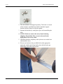
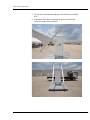
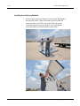
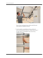
MULTIPANEL SOLAR ARRAY DEPLOYMENT Solarcraft Solar System Solarcraft, Inc. 12300 Dairy Ashford Road Sugar Land TX 77478 USA 877.340.1224 toll free www.solarcraft.net © Solarcraft, Inc. 2012 Solar System Deployment 6-Jul-12 Installing the Solar Array....................................................................... 3 Setting up the array frame:................................................................................3 Installing the Sub-‐Array Modules.......................................................................6 Connecting the Homerun Cables .......................................................................8 Troubleshooting ................................................................................... 9 Warranty Summary ............................................................................ 10 Customer Service ................................................................................ 10 2 Deployment Guide Solar System Deployment Installing the Solar Array This system is shipped with the solar modules separate, and the array frame folded down to avoid damage in shipment. IMPORTANT: It is very important to position the solar panel assembly so the panels face due south. If in doubt, use a compass. This is critical to the performance of the system. The solar panels must not be blocked by obstructions such as trees, bushes, buildings fences, etc. Even partial shading can cause a significant power loss in the solar array. Setting up the array frame: 1. The mounting bolts used to assemble the array frame bracket can be found in a plastic bag inside of the enclosure. Remove the mounting bolts and have them ready. User Manual 3 6-Jul-12 Solar System Deployment 2. The solar modules are shipped separately. The frame is secured to the enclosure, and folded up with the aluminum support brackets (kickers) bolted or zip-tied together. 3. Separate the brackets by cutting the zip tie or disassembling the bolts. 4. NOTE: If bolts are used on the array frame in during shipping, discard them. They are not to be used in the deployment of the array frame. 5. Unfold the brackets completely and lay them to rest on the base underneath the array. 6. Elevate one bracket to the pre-drilled hole at the appropriate angle and, with the nut facing inside, place the bolt in the predrilled hole to hold the array in place. 4 Deployment Guide Solar System Deployment 7. Elevate the second bracket and place the bolt in its pre-drilled hole. 8. Tighten all of the bolts, including the upper two bolts that secure the frame to the enclosure. User Manual 5 Solar System Deployment 6-Jul-12 Installing the Sub-Array Modules 1. The next steps require a minimum of two persons. Beginning at the top of the frame, lift the first module sub-array onto the frame and slide to the TOP of the frame. With one person securely bracing the sub-array in place, the second person inserts the bolts to attach the modules to the frame. 6 Deployment Guide Solar System Deployment Repeat for the remaining sub-array modules until all four subarray modules are installed to the frame. 2. Once the modules are installed to the frame, go back and unscrew the array bolts shown below, rotate the (Insert name of the plate) plate 90°, and retighten to secure the sub-array modules to one another User Manual 7 Solar System Deployment 6-Jul-12 Connecting the Homerun Cables 1. Each solar panel has a connection box and cable. Referred to as a homerun cable, that connects the modules to the batteries inside the enclosure. To make this connection, locate the cable clamps on the frame rail. Loosen the cable clamp screw and run the cable through the cable clamp on the rail. Tighten the clamp screw after the cables are run. 2. Insert the cables into the enclosure through the cable glands. 8 Deployment Guide Solar System Deployment 3. Cut and terminate the homerun cables according to the schematic at the back of this manual. Troubleshooting For troubleshooting convenience the circuit breaker and fuse terminals on the backplane have screw contacts in them for a digital meter probe. You can troubleshoot most of the system at the electronics backplane. Solar array- power from the array assembly can be checked for 12V or 24V operation. To check circuit breaker - first put your meter in diode check or ohm check position, place probe on terminal screw above and below the fuse holder and check for continuity. It should show almost no resistance in the OHM mode and beep in the diode mode. (Only one check is necessary, not both). To check voltage - put the positive probe at the fuse and the negative probe on the negative terminals. To check current - turn off the circuit breaker on the circuit to be checked, set meter to current and use the meter to jump across the open fuse holder. This shunts the solar array current through your meter and you should be able to read current directly on your meter. In full sun the panels will each produce about 4.5 A of current. In less than full sun, the current will be lower, as the solar panel current output is a direct function of sunlight intensity. Both sets of panels should be putting out the same current (+/- 10%) regardless of sunlight intensity. If the batteries are fully charged, you will need to turn off the solar breaker, put your positive lead on the input side of the fuse and your negative lead on the negative terminals and read the current. If the batteries are above 13.0 volts for 12V systems, or 26.0 volts for 24V systems, do not use this procedure, as the voltage regulator will not pass current when the batteries are fully charged, and you will get a false reading, Make sure your current meter has sufficient capability. You can check the battery voltage and load current the same way, but DO NOT check the battery current through your meter. If you short the batteries, you could blow your circuit breaker and possibly damage your meter or melt the test leads. To check load - turn the load breaker off, put the meter leads on either sides of the open component and read the current. The following list of items should be checked if there is a problem with the system, such as failing to work, or the batteries not holding a charge. User Manual 9 Solar System Deployment 6-Jul-12 1. Are the battery terminals tight and free of corrosion? 2. Is the solar fuse or circuit breaker in good working condition? 3. Is the battery fuse or circuit breaker in good working condition? 4. Are the load fuses or circuit breaker in good working condition? 5. Is the LED display on Prostar and Tristar solar controllers working? 6. Are the LED lights on SunSaver solar controllers showing charge status or LVD status? 7. Are the solar panels clean of residue and dirt? 8. Caution, do not clean hot solar panels with cold water, as the glass panel could shatter and break. 9. Are all wire terminations on the din rail terminals tight and fully connected? 10. Has a battery gone bad, such as indicated by a low voltage compared to the other batteries? Warranty Summary Solarcraft warrants this system to be free from defects in materials and workmanship for a period of 5 years from date of purchase. Batteries carry a prorated 3-year warranty. This warranty does not cover abuse, neglect, improper installation, acts of God or vandalism. Please contact Solarcraft for any warranty issues. Customer Service Solarcraft, Inc. 12300 Dairy Ashford Sugar Land, Texas 77478 (877) 340-1224 toll free 281.340.1224 local www.solarcraft.net [email protected] 10 Deployment Guide