1
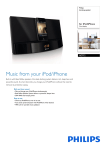
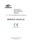
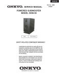
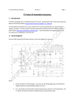
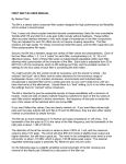
®
INSTRUCTIONS
A06
Integarted Amplifier
Chapter 1
Important Safety Instruction
!
Dangerous Voltage
The lightning flash with arrowhead symbol, within an equilateral triangle, is
intended to alert the user to presence of uninsulated “Dangerous voltage” within
the product’s enclosure that may be of sufficient magnitude to constitute a risk of
electric shock to persons.
Important Instructions
!
The exclamation point within an equilateral triangle is intended to alert the user to
presence of important operating and maintenance (servicing) instructions in the
literature accompanying the appliance.
1
Chapter 1
Important Safety Instruction
1.1 Before Use
Please read all instructions and precautions carefully and completely before operating yourA06 integrated amplifier.
1.Read these instructions.
2.Keep these instructions.
3.Heed all warnings.
4.Follow all instructions.
5. Do not use this apparatus near water.
6. Clean only with dry cloth.
7. Always keep this unit out of the reach of children.
8. Do not install near any heat sources such as radiators, heat registers, stoves, or other apparatus ( including
amplifiers) that produce heat.
9. Protect the power cord from being walked on or pinched particularly at plugs, convenience receptacles, and the point
where they exit from the apparatus.
10. Unplug this apparatus during lightning storms or when unused for a long time.
11. Always disconnect your entire system from the AC mains before connecting or disconnecting any cable, or when
cleaning any component.
12. This product must be terminated with a three conductor AC mains power cord which includes an earth ground
connection, to prevent shock hazard, all three connections must always be used.
13.AC extension cords are not recommended for use with this product.
14. Never use flammable or combustible chemicals for cleaning audio components.
15. Never operate this product with any cover removed.
16. Never pour or spill liquids directly onto this unit.
17. Never block air flow through ventilation slots or heat sinks.
18.Never by pass any fuse.
19. Never replace any fuse with a value or type other than those specified.
20. Never attempt to repair this product, if a problem occurs, contact your dealer.
21. Never expose this product to extremely high or low temperatures.
22. Never operate this product in an explosive atmosphere.
1.2 Check Accessory
Unpack your A06 integrated amplifier and keep all packing materials for future transport or service, locate and remove all
accessory items from the accessory box within the controller shipping carton.
Accessories Included:
1. AC power cord × 1
2. Remote controller × 1
2
3. User manual (This manual)
Chapter 2
Introduction
2.1 Product Features
A
06 follows the simple design principle. The standard IEC power outlet affords very
convenience to change the power cord. Besides, there are 5 RCA analog inputs and one
group of binding posts for loudspeakers.
It adopts quality annular transformer to supply power and the relay take charges of the input switch. In
order to increase the reliability and avoid the bad contact of the relay incurred by improper use, it
cancelled the relay of the loudspeaker output. The voltage amplifier stage adopts selective AD712 for
amplifying while the first stage of the power amplifying adopts high quality Toshiba 2SK170 F.E.T to
achieve differential amplifying. The HITACHI 2SD667/2SB647 geminate transistors are used for voltage
amplifying. The output stage on both channels adopt 2 pairs of Sanken high current 2SC4468/2SA1695
geminate transistors. This unit has perfect self-protection functions: power on delay protection, current
protection and power off protection, which could ensure this unit work in safe condition all the time.
3
Chapter 2
Introduction
2.2 Front Panel
1. Sensor window for remote control
The remote control receiving window will receive the controlling signal produced by the remote
controller.
2. Power button
Press this button, the current will be put through; press it again, the current will be cut off.
3. Power Indicator
This indicator will be light when this unit is switched on.
4. AUX button
AUX paths can be connected through it. The AUX paths contains two paths, one is coaxial
analog input, the other is USB input, which is used to connect to the PC.
5. Tape button
It’s used to select the signal path (Tape) on the rear panel according your corresponding choice.
6. DVD button
It’s used to select the signal path (DVD) on the rear panel according your corresponding choice.
7. Tuner button
It’s used to select the signal path (tuner) on the rear panel according your corresponding choice.
8. CD button
It’s used to select the signal path (CD) on the rear panel according your corresponding choice.
9. Sound volume control knob
The sound volume will be increased while this button is adjusted clockwise and decreased while
adjusted anticlockwise.
4
Chapter 2
Introduction
2.3 Rear Panel
Panel
Coaxial
1
2
3
4
5
6
1.Audio input
The signal input port for corresponding signal source.
2. USB input socket
Please connect this port to the computer by USB connection cable. (USB connection cable is not
attached)
3.SPEAKERS - The right channel speaker binding post
Connect it to the speaker for the right channel by the speaker cable. This unit is suitable to match the
speakers with the impedances between 4 to 16 ohms.
4.SPEAKERS - The left channel speaker binding post
Connect it to the speaker for the left channel by the speaker cable. This unit is suitable to match the speakers
with the impedances between 4 to 16 ohms.
5.Fuse Socket
Use to install the fuse.
6.Power Input
Connect this port to the power socket by the power cord attached. Please pay attention to the power
supply available range indicated in this manual.
2.4 Remote Controller
1
Infrared transmission window.
2
TAPE: Sound source selection button. Switch the input to TAPE channel.
3
DVD: Sound source selection button. Switch the input to DVD channel.
4
TUNER: Sound source selection button. Switch the input to TUNER channel.
5
AUX: Sound source selection button. Switch the input to AUX channel.
Volume+/Volume-: Sound volume control button.Adjust the Volume level.
CD: Sound source selection button. Switch the input to CD channel.
5
Chapter 3
Precaution
3.1 The Installation of the Battery
Install batteries
Before using the remote controller for the first time, you need to install the new
batteries in the remote controller.(Fig 1)
Process
1. Use the tool to remove the rear cover of the remote controller.
2. Install the 2 batteries (AAA) with correct +/- polarity.
3. Reinstall the rear cover of the remote control unit.
Battery replacement
AAA
1. Use the tool remove the rear cover of the remote controller.
2. Take out the old batteries from remote control unit.
3. Install the 2 batteries (AAA) with correct +/- polarity.
(Fig 1)
4. Reinstall the rear cover of the remote control unit.
Caution
1. Do not use new and old batteries simultaneously.
Battery Reclaim
2. Batteries with similar shapes may have different rated voltages. Be sure to
use the correct batteries.
Please send the waste batteries to local
battery reclaim center. DO NOT discard
the waste batteries discretionarily, in
order to avoid environment pollution.
3. Remove batteries from the remote control unit if it will not be used for a long
period of time.
4. After a certain period of time’s use, if the valid distance of the remote
controller is shortened, please replace the batteries in time.
3.2 For Using the Remote Controller
You can achieve the following functions conveniently by using the remote controller.
CD
U
AUX
Volume Control
Input Selection
Control the amplifier by using the remote
controller:
1. The maximum valid distance is 5 meters.
2. Please locate the remote controller towards
the remote receiving window to make sure the
amplifier can work normally.
6
Chapter 4
Operation Instruction
4.1 Connection
Connection
A06 Amplifier
INPUT
Right Channel
Left Channel
Connection to
Power Supply
Audio Output
USB
SACD- 1 PLA YER
CD/SACD
POW ER
PC
CD/SACD
1.Before using this machine, you have to connect it to sound sources (such as CD player, DVD player, SACD player) by
signal cable.Also you need to check if the signal connection of the left and right channel is correct and reliable.
2.Before connecting the machine to the right and left channel speaker by speaker cables, it’s strongly suggested that you
consult the dealer if your speaker cable is available for this machine and make sure of the right channel and polarity.
3.Please be very careful when connecting the power cable. Make sure the power supply has been cut off before
connecting to the accessory power cable. If you do have to use other power cables, please check if the specifications are
up to the requirements of this machine. We claim that we are not reliable for the damages caused by the use of other
power cables.
Please make sure all the power supplies have been cut off before connecting any
cable to this machine. If you have no ability to install this machine, please ask
those who are guided or are capable to accomplish the installation or connection.
7
Chapter 5
Q&A
5.1 Q&A
In order to help you to operate this unit more conveniently, we will answer the common questions during operation. If you
need more information, please visit our website: www.xindak.com, send your E-mail to [email protected] or directly call
at +86-28-84711993 betweenAM 8:30-PM5:30 Chinese time. We will try our best to offer you the high-quality service.
Q: Why it needs to wait for several seconds after the unit is turned on?
A: In order to avoid the damage to speaker caused by current surge on power on there is a little delay after the unit is turned
on.
Q: Why it needs to adjust the volume to the minimum before this unit is turned on?
A: The purpose of doing so is to avoid the damage of the speakers or your hearing in case that the volume was adjusted to
the maximum carelessly by your families. We strongly suggest you follow the instructions of this manual.
Q: How to replace the fuse(safety cutout)?
A: If the fuse is smelted, please pull out the power cord on the rear panel and open the fuse cover on the power input cover.
Please watch the smelted fuse carefully after the fuse is picked up, if there is no nigrescence inside the fuse, please directly
replace the fuse with a new one with the same specifications; if there is nigrescence inside the fuse, which means there
might be some malfunction of your machine, we suggest you contact your dealer or the authorized service centre of
Chengdu Xindak Electronic Co., LTD firstly.
Q:Why sometimes all the indicators are all off?
A: This product has self-protect function against over-heat and can automatically restart. The maximum temperature is
90°C. When the temperature is higher than the peak value, power supply will be cut off automatically and all the indicators
will be off. When the temperature decreases down to 75°C, power supply will be automatically recovered and the default
input channel is CD channel. If it is the bad ventilation which caused the over-heat, please check whether the load is
between 4Ω-16Ω and check the ventilation conditions.
Notice: if you have been confronted any problems when using this product or have any suggestion to tell us, please visit
the wesite of xindak: http://www.xindak.com, you may access our instant technique support here.
8
Specifications
Chapter 6
6.1 Specifications
< Power output
80w per channel at 8ohm
< Frequency response
5Hz - 100KHz(±3dB)
< Audio inputs
five pairs single-ended on RCA
< Audio outputs
two pairs speaker binding posts
< Signal-to-noise ratio
more than 88dB ( A Weight)
< Distortion
1KHz with no more than 0.03%
< Dimensions (WXDXH)
430mmX352mmX110mm
< Input sensitivity
300mV
< Minimum load
4 Ohm
< Gross weight
8.5Kg
< Supply voltage
Specified on rear panel
< Remote controllable
Yes
9
No.126, Section 2, East 1 Round Chengdu, Sichuan, China
P.C. 610051
You can find your nearest authorized distributor and more product information on our website:
www.xindak.com
© 2006
XD3.834.067 SMS
Print in China