1
GE Healthcare
DYEnamic ET Terminator
Matrix Standard for the
ABI 3700
For use with ABI 3100, 3700 and 3730/3730XL
Product Booklet
Code:
US84001
Page finder
1. Legal
3
2. Handling
2.1. Safety warnings and precautions
2.2. Storage
5
5
5
3. Introduction
6
4. Components of the kit
7
5. Materials not supplied
8
6. Protocols
6.1. Spectral calibration of the AB13700 for DYEnamic
ET Terminators
6.1.1. Preparation of DYEnamic ET Terminator Matrix
Standard
6.1.2. Performing a spectral calibration
6.1.3. Performing a spectral calibration run for POP™-5
6.1.4. Performing a spectral calibration run for POP-37
6.1.5. Performing a spectral calibration run for POP-6
6.2. Spectral calibration of the ABI 3100 for DYEnamic ET
Terminators
6.2.1. Preparation of DYEnamic ET Terminator Matrix
Standard
6.2.2. Performing a spectral calibration
6.3. Spectral calibration of the ABI 3730/3730XL for
DYEnamic ET Terminators
6.3.1. Preparation of DYEnamic ET Terminator Matrix
Standard
6.3.2. Creation of Spectral Protocol
6.3.3. Creating a Plate Record
6.3.4. Adding a Plate to the Run Scheduler
6.3.5. Evaluating Spectral Calibration Results
6.3.6. Editing Spectral calibration Files
9
2
9
9
9
10
13
15
18
18
19
22
22
23
24
25
25
26
1. Legal
GE and GE monogram are trademarks of General Electric Company.
Amersham and DYEnamic are trademarks of GE Healthcare
companies.
This kit is sold pursuant to Authorization from PE Applied Biosystems
under one or more of the following U.S. Patents: 4,849,513;
4,855,255; 5,015,733; 5,118,800; 5,118,802; 5,161,507; 5,171,534;
5,242,796; 5,306,618; 5,332,666; and 5,366,860, and corresponding
foreign patents and patent applications. The purchase of this kit
includes limited non-transferable rights (without the right to resell,
repackage, or further sublicense) under such patent rights to use
this kit for DNA sequencing or fragment analysis, solely when used
in conjunction with an automated instrument for DNA sequencing
or analysis which have been authorized for such use by Applied
Biosystems, or for manual sequencing. Purchase of this product
does not itself convey to the purchaser a complete license or right
to perform automated DNA sequence and fragment analysis under
the subject patents. No other license is hereby granted for use of
this kit in any other automated sequence analysis instrument. The
rights granted hereunder are solely for research and other used that
are not unlawful. No other license is granted expressly, impliedly, or
by estoppel.
Further information on purchasing licenses to perform DNA
sequence and fragment analysis may be obtained by contacting the
Director of Licensing at Applied Biosystems, 850 Lincoln Centre Drive,
Foster City, California 94404.
GE HEALTHCARE IS LICENSED AS A VENDOR FOR AUTHORIZED
SEQUENCING AND FRAGMENT ANALYSIS INSTRUMENTS.
Energy Transfer dyes and primers—US Patent numbers: 5,654,419,
5,688,648 and 5,707,804.
3
© 2006 General Electric Company – All rights reserved.
GE Healthcare reserves the right, subject to any regulatory and
contractual approval, if required, to make changes in specification
and features shown herein, or discontinue the product described at
any time without notice or obligation.
Contact your GE Healthcare representative for the most current
information and a copy of the terms and conditions.
http//www.gehealthcare.com/lifesciences
GE Healthcare UK Limited.
Amersham Place, Little Chalfont,
Buckinghamshire, HP7 9NA UK
4
2. Handling
2.1. Safety warnings
and precautions
data sheet(s) and/or safety
statement(s) for specific advice.
Warning: For research use
only. Not recommended
or intended for diagnosis
of disease in humans or
animals. Do not use internally
or externally in humans or
animals.
2.2. Storage
Store at -15°C to -30°C.
All chemicals should be
considered as potentially
hazardous. We therefore
recommend that this product is
handled only by those persons
who have been trained in
laboratory techniques and
that it is used in accordance
with the principles of good
laboratory practice. Wear
suitable protective clothing
such as laboratory overalls,
safety glasses and gloves.
Care should be taken to avoid
contact with skin or eyes. In
the case of contact with skin
or eyes wash immediately
with water. See material safety
5
3. Introduction
The DYEnamic ET Terminator Matrix Standard for the ABI 3700,
ABI3730, ABI 3730XL (US84001) is formulated to create a spectral
matrix with the ABI 3700 and ABI 3100 sequencing instruments.
This spectral calibration must be performed prior to analysis of
samples labelled with any dye set not previously used with the
instrument. It is strongly recommended that the user read and
thoroughly understand the section of the ABI 3100 user’s manual
(copyright, 2001) titled “Spectral Calibration” (pages 4-15 to 4-50).
ABI 3730/3730x1 User’s guide (copyright, 2002) titled “Spectral
Calibration” (pages 4-11 to 4-28).ABI 3700 user’s manual (copyright,
1999) titled “Performing a Spectral Calibration” (pages 6–21 to 6–56)
before attempting to create a matrix for DYEnamic ET terminators.
6
4. Components of the kit
This reagent has been tested extensively and its concentration
adjusted to meet rigorous standards. It is strongly recommended
that the reagent be used exactly as described in this protocol.
The product consists of the following solution: DYEnamic™ ET
Terminator Matrix Standard for the ABI™ 3700, 3730, 3730XL
(40 μl).
Each tube contains enough matrix standard to perform one spectral
calibration on the ABI 3700 1 calibration on 3730, 1/2 calibration
on 3730XL sequencing instrument, or eight calibrations on the ABI
3100. The product should be stored at -15°C to -30°C (not in a frostfree freezer). When not in a freezer, keep the reagent on ice prior to
use.
7
5. Materials not supplied
Reagents
• Water—Only use deionized, distilled water with the DYEnamic ET
Terminator Matrix Standard.
Equipment
• Liquid-handling supplies—Microcentrifuge tubes
(200 μl), micropipettes, microcentrifuge, vortex mixer.
• Instrument—This product is designed for use with the ABI 3730,
3730XL, ABI 3700 and ABI 3100 sequencing instruments.
8
6. Protocols
6.1. Spectral calibration of the ABI 3700 for
DYEnamic ET Terminators
6.1.1. Preparation of DYEnamic ET Terminator Matrix Standard
1. Briefly centrifuge the tube containing the DYEnamic ET Terminator
Matrix Standard to bring the contents (40 μl) to the bottom of the
tube.
2. Add 360 μl of distilled water to the tube that contains the matrix
standard.
3. Mix the contents of the tube thoroughly by vortexing vigorously.
4. Briefly centrifuge the tube.
5. Transfer 200 μl of the matrix standard solution into each of
two 200 μl microtubes as recommended by the instrument
manufacturer.
6.1.2. Performing a spectral calibration
See pages 6–25 of the ABI 3700 user’s manual for general guidelines
for performing a default calibration. To create a spectral matrix for
DYEnamic ET terminator chemistry, follow the protocol below.
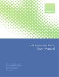
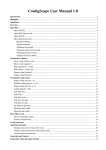
1. Firmly place the two tubes containing the ET terminator matrix
standard into the right bar in slot positions 9 and 10 as shown in
Figure 1 and on pages 6–25 in the ABI 3700 user’s manual.
Left Bar
Right Bar
Fig 1. Matrix standard loading position.
9
6.1.3. Performing a spectral calibration run for POP™-5
1. Open the ABI 3700 Data Collection software. Initiate a spectral
calibration run by selecting the Spectral Run command under
the Run Setup page. This command opens the Calibration
Module and Dye Set dialog window from which the appropriate
calibration module, dye set, and parameter files are selected.
Note: For a schematic of the procedure, see pages 6–26 in the
ABI 3700 user’s manual.
2. Using the pull-down menu under Calibration Module, choose the
SpecSQ1_1POP5DefaultModule file for spectral calibration for
POP-5.
Note: For a schematic of the procedure, see pages 6–26 in the
ABI 3700 user’s manual.
3. IMPORTANT! Under Dye Set, choose F from the pull-down menu.
3.4. IMPORTANT! Under Parameter File, choose SeqStd
(AnyDyeSet).par from the pull-down menu.
5. Click OK to accept these chosen fields.
6. The spectral run will be displayed in the run queue. This action will
simultaneously engage the Start Run button. Activate the run by
clicking on Start Run.
7. After electrophoresis is completed (< 3 hours), a dialog window
displays “Spectral Calibration Result” as shown on pages 6–29 in
the ABI 3700 user’s manual. This display indicates the number of
capillaries (caps) that passed spectral calibration. For a schematic,
see pages 6–29 in the user’s manual. Accept the result by clicking
OK. The software will automatically assign proper calibration
values to failed caps from adjoining successful caps. The capillary
status bar will indicate passed caps in black and questionable caps
in yellow.
10
Note: For further information on the significance of color coding in
the capillary status bar, see pages 6–29 and 5–68 in the ABI 3700
user’s manual.
8. Upon completion of the spectral run and data processing, the
quality of the spectral profile (the emission spectra for all four dyes)
for each capillary must be examined. The condition number is a
measure of the spectral overlap of the dyes. As the spectral overlap
of a dye set decreases, so does the condition number. A condition
number of 1.0 indicates no spectral overlap for a particular dye set.
The expected condition number for ET dyes analyzed on the ABI
3700 is 7.3 ± 0.5. The Q-value is a measure of how well the spectral
calibration fits the data it was created from. A Q-value of 1.0
represents a perfect fit. Any spectral calibration with a Q-value less
than 0.92 will automatically fail the calibration and be replaced with
spectral calibration data from an adjacent capillary. Those caps
that have a questionable matrix should be replaced with data from
a successful matrix.
Note: For further information and a schematic, see “Reviewing and
Overriding the Spectral Calibration Profiles” on pages 6–34 of the
ABI 3700 user’s manual.
To review the calibration profile, open the Data Collection software.
Go to the Data Acquisition menu and open the Override Spectral
Calibration function. A dialog window titled Select the dye set to
display will appear.
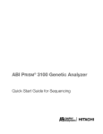
9. Select F from the pull-down menu (IMPORTANT!). Click OK. This
action opens the dialog window titled Spectral Calibration
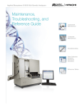
Profile for F. The fluorescence emission spectra for all four dyes
in a particular capillary will be displayed as shown in Figure 2.
10. Examine the results for each cap and verify that the profile is
similar to that shown in Figure 2.
11
Note: For additional schematic illustrations, see pages 6–35 of the
ABI 3700 user’s manual.
11. Although the software assigns values from successful caps to
failed caps, in some instances the profile may not be similar to
the one shown in the illustration. When this occurs, replace the
values manually by using the values from a successful adjacent
matrix. At the bottom left of the dialog box, under Override
matrix from another source, click on the button From capillary,
which allows the choice of values from any capillary. Choose any
acceptable capillary.
Fig 2. Spectral calibration profile for F using POP-5 with the ABI 3700.
12
6.1.4. Performing a spectral calibration run for POP-37
1. Open the ABI 3700 Data Collection software. Initiate a spectral
calibration run by selecting the Spectral Run command under
the Run Setup page. This command opens the Calibration
Module and Dye Set dialog window from which the appropriate
calibration module, dye set, and parameter files are selected.
Note: For a schematic of the procedure, see pages 6–26 in the
ABI 3700 user’s manual.
2. Use the pull-down menu under Calibration Module and choose
the SpecSQ1_2POP37DefaultModule file for spectral calibration
for POP-37.
Note: For a schematic of the procedure, see pages 6–26 in the
ABI 3700 user’s manual.
3. IMPORTANT! Under Dye Set, choose F from the pull-down menu.
4. IMPORTANT! Under Parameter File, choose SeqStd(AnyDyeSet).
par from the pull-down menu.
5. Click OK to accept these chosen fields.
6. The spectral run will be displayed in the run queue. This action will
simultaneously engage the Start Run button. Activate the run by
clicking on Start Run.
7. After electrophoresis is complete (< 3 hours), a dialog window
displays “Spectral Calibration Result” as shown on pages 6–29 in
the ABI 3700 user’s manual. This display indicates the number of
capillaries (caps) that passed spectral calibration. For a schematic,
see pages 6–29 in the user’s manual. Accept the result by clicking
OK. The software will automatically assign proper calibration
values to failed caps from adjoining successful caps. The capillary
status bar will indicate passed caps in black and questionable caps
in yellow.
13
Note: For further information on the significance of color coding in
the capillary status bar, see pages 6–29 and 5–68 in the ABI 3700
user’s manual.
8. Upon completion of the spectral run and data processing, the
quality of the spectral profile (the emission spectra for all four dyes)
for each capillary must be examined. The condition number is a
measure of the spectral overlap of the dyes. As the spectral overlap
of a dye set decreases, so does the condition number. A condition
number of 1.0 indicates no spectral overlap for a particular dye set.
The expected condition number for ET dyes analyzed on the ABI
3700 is 7.3 ± 0.5. The Q-value is a measure of how well the spectral
calibration fits the data it was created from. A Q-value of 1.0
represents a perfect fit. Any spectral calibration with a Q-value less
than 0.92 will automatically fail the calibration and be replaced with
spectral calibration data from an adjacent capillary. Those caps
that have a questionable matrix should be replaced with data from
a successful matrix.
Note: For further information and a schematic, see “Reviewing and
Overriding the Spectral Calibration Profiles” on pages 6–34 of the ABI
3700 user’s manual.
9. To review the calibration profile, open the Data Collection
software. Go to the Data Acquisition menu and open the
Override Spectral Calibration function. A dialog window titled
Select the dye set to display will appear.
10. Select F from the pull-down menu (IMPORTANT!). Click OK. This
action opens the dialog window titled Spectral Calibration
Profile for F. The fluorescence emission spectra for all four dyes
in a particular capillary will be displayed as shown in Figure 2.
11. Examine the results for each cap and verify that the profile is
similar to that shown in Figure 2.
14
Note: For additional schematic illustrations, see pages 6–35 of the
ABI 3700 user’s manual.
12. Although the software assigns values from successful caps to
failed caps, in some instances the profile may not be similar to
the one shown in the illustration. When this occurs, replace the
values manually by using the values from a successful adjacent
matrix. At the bottom left of the dialog box, under Override
matrix from another source, click on the button From capillary,
which allows the choice of values from any capillary. Choose any
acceptable capillary.
6.1.5. Performing a spectral calibration run for POP-6
1. Open the ABI 3700 Data Collection software, and then open the
Module Editor listed under the Instrument Utilities menu. Select
the Others tab under the module menu within the Module Editor.
Load the SpectSQ1_1POP6DefaultModule parameters into the
Module Editor by clicking on its listing within the Others tab.
2. Scroll down to the Run Time parameter (number 15) listed in the
Module Parameters window. Edit the Run Time by clicking on
the default value of 2 700 seconds, and replace that with 4 000
seconds.
3. Click the Save As button and enter SpecSQ1_1POP6Extended as
the new module file name. Click OK to save the new parameters.
Click Done to exit the Module Editor.
4. In the Data Collection software, initiate a spectral calibration run
by selecting the Spectral Run command within the Run Setup
page. This opens the Calibration Module and Dye Set dialog
window. From here, the appropriate type of calibration module,
dye set, and parameter files can be selected for performing a
spectral calibration.
15
Note: For a schematic of the procedure, see pages 6–26 in the
ABI 3700 user’s manual.
5. Using the pull-down menu under Calibration Module choose the
SpecSQ1_1POP6Extended file for spectral calibration for POP-6.
Note: For a schematic of the procedure, see pages 6–26 in the
ABI 3700 user’s manual.
6. IMPORTANT! Under Dye Set, choose F from the pull-down menu.
7. IMPORTANT! Under Parameter File, choose SeqStd (AnyDyeSet).
par from the pull-down menu.
8. Click OK to accept these chosen fields.
9. The spectral run will be displayed in the run queue. This action
will simultaneously engage the Start Run button. Activate the
run by clicking on Start Run.
10. After the run is completed (< 3 hours), a dialog window will
display “Spectral Calibration Result” as shown on pages 6–29 in
the ABI 3700 user’s manual. This display indicates the number of
caps that passed spectral calibration. For a schematic, see pages
6–29 in the user’s manual. Accept the result by clicking OK. The
software automatically assigns proper calibration values to failed
caps from the adjoining successful caps. The capillary status bar
indicates passed caps in black and questionable caps in yellow.
Note: For further information on the significance of color coding in
the capillary status bar, see pages 6–29 and 5–68 in the ABI 3700
user’s manual.
11. Upon completion of the spectral run and data processing, the
quality of the spectral profile (the emission spectra for all four
dyes) for each capillary must be examined. The condition number
is a measure of the spectral overlap of the dyes. As the spectral
overlap of the dyes decrease, so does the condition number.
A condition number of 1.0 indicates no spectral overlap for a
16
particular dye set. The expected condition number for ET dyes on
the ABI 3700 is 7.3 ± 0.5. The Q-value is a measure of how well
the spectral calibration fits the data it was created from. A Qvalue of 1.0 represents a perfect fit. Any spectral calibration with
a Q-value less than 0.92 will automatically fail the calibration
and be replaced with spectral calibration data from an adjacent
capillary. Those caps that have a questionable matrix should
be replaced with data from a successful matrix. For further
information and a schematic, see “Reviewing and Overriding
the Spectral Calibration Profiles” on pages 6-34 of the ABI 3700
user’s manual.
To review the calibration profile, open the Data Collection software.
Go to the Data Acquisition menu and open the Override Spectral
Calibration function. A dialog window titled Select the dye set to
display will appear.
12. Select F from the pull-down menu (IMPORTANT!). Click OK. This
action opens a dialog window titled Spectral Calibration Profile
for F. The fluorescence emission spectra for all four dyes in a
particular capillary is displayed as shown in Figure 2.
13. Examine the results for each cap and verify that the profile is
similar to that shown in Figure 4.
Note: For additional schematic illustrations, see pages 6–35 of the
ABI 3700 user’s manual.
14. Although the software assigns values from successful caps to
failed caps, in some instances the profile may not be similar to
the one shown in the illustration. When this occurs, replace the
values manually by using the values from a successful adjacent
matrix. At the bottom left of the dialog box, under Override
matrix from another source, click on the button From capillary
which allows the selection of values from any capillary. Choose
any acceptable capillary.
17
6.2. Spectral calibration of the ABI 3100 for
DYEnamic ET Terminators
The DYEnamic ET Terminator Matrix Standard is formulated for
creating a spectral matrix with the ABI 3100 sequencing instrument.
This spectral calibration must be performed prior to analysis of
samples labelled with any dye set not previously used with the
instrument. It is strongly recommended that the user read and
thoroughly understand the section of the ABI 3100 user’s manual
(copyright, 2001) titled “Performing a Spectral Calibration” (pages
4–15 to 4–49) before attempting to create a matrix for DYEnamic ET
terminators.
6.2.1. Preparation of DYEnamic ET Terminator Matrix Standard
1. Briefly centrifuge the tube containing the DYEnamic ET Terminator
Matrix Standard to bring the contents (40 μl) to the bottom of the
tube.
2. Transfer 5 μl of the DYEnamic ET Terminator Matrix Standard into
a tube containing 195 μl of distilled water.
3. Mix the contents of the tube thoroughly by vigorous vortexing.
4. Briefly centrifuge the tube and dispense 10 μl of the DYEnamic
ET Terminator Matrix Standard into a 96-well plate as shown
below (Figure 3). It is crucial to centrifuge the plate to position the
samples at the bottom of each well.
5. Assemble the plate for loading onto the ABI 3100 (see pages 3–9
of the ABI 3100 user’s manual).
18
Fig 3. Matrix standard loading positions.
6.2.2. Performing a spectral calibration
For general guidelines on performing a default calibration, see pages
4–17 of the ABI 3100 user’s manual. To create a spectral matrix for
DYEnamic ET terminator chemistry, follow the protocol below.
1. Place the plate on the autosampler
Note: For a schematic of the procedure, see pages 4–24 in the
ABI 3100 user’s manual.
2. Open the 3100 Data Collection software and initiate a spectral
calibration run by selecting New within the Plate View page.
This opens up the Plate Editor dialog box. Name the plate, select
Spectral Calibration, and select 96-Well plate type. Click Finish.
This opens the Plate Editor spreadsheet.
3. Within the Plate Editor spreadsheet, complete the following for
the 16 samples in the sample plate:
3.1. Name the samples.
19
3.2. IMPORTANT! Select Dye Set F.
3.3. Select the run module appropriate for your capillary array
size:
36 cm: Spect36_POP6DefaultModule
50 cm: Spect50_POP6DefaultModule
80 cm: Spect80_POP4DefaultModule
3.4. IMPORTANT! Select the spectral calibration parameters,
SeqStd(AnyDyeSet).par.
3.5. Click OK.
4. The newly created plate record then appears in the Pending Plate
Records table of the Plate Setup page. In the Plate Setup page,
select the newly created plate from the Pending Plate Records
table.
5. Click on the graphic that corresponds to the plate on the
autosampler. The plate then moves from the Pending Plate
Records table to the Linked Plate Records table. For a pictorial
representation see pages 3–39 in the ABI 3100 user’s manual.
6. Click the Run Instrument button on the toolbar to begin the run.
7. After completing the run (40–65 minutes), a dialog window
displays “Spectral Calibration Result” as shown on pages 4–23
in ABI 3100 user’s manual, indicating the number of caps that
passed spectral calibration. Accept the result by clicking OK. The
software then automatically assigns proper calibration values to
failed caps from the adjoining successful caps.
8. Upon completion of the spectral run and data processing, the
quality of the spectral profile (the emission spectra for all four
dyes) for each capillary must be examined. Any capillary that
generated a questionable matrix should be carefully examined
and replaced with data from a successful matrix. Instructions for
20
matrix replacement are provided in the ABI 3100 user’s manual on
pages 4–27, “Overriding a Spectral Calibration Profile”.
9. The condition number is a measure of the spectral overlap of
the dyes. As the spectral overlap of a dye decreases, so does the
condition number. A condition number of 1.0 indicates no spectral
overlap for a particular dye set. The expected condition number
for ET dyes on the ABI 3100 is 7.3 ± 0.5. The Q-value is a measure
of how well the spectral calibration fits the data it was created
from. A Q-value of 1.0 represents a perfect fit. Any spectral
calibration with a Q-value less than 0.92 will automatically fail the
calibration and be replaced with spectral calibration data from an
adjacent capillary.
Review the calibration profile using the following steps. Open the
Data Collection software; select Override Spectral Calibration
from the File Menu. A dialog window titled Select the dye set to
display appears. Select F from the pull down menu (IMPORTANT!).
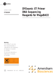
Click OK. This action opens the dialog window Spectral Calibration
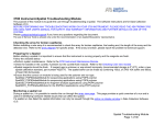
Profile for F. The fluorescence emission spectra for all four dyes in
a particular capillary is displayed as shown in Figure 4. Examine the
results for each cap and verify that it is similar to the one shown in
this example and as illustrated on page 4-29 of the ABI 3100 user’s
manual. Although, the software assigns values from successful caps
to failed caps in some instances, the profile may not be similar to the
one shown in the illustration. When this happens, manually replace
the values with the data from a successful adjacent matrix. At the
bottom left of the dialog box, under Override matrix from another
source click on the button From capillary. These commands allow
you to select a value from any acceptable capillary.
10. Examine the results for each cap and verify that the profile is
similar to that shown in Figure 4.
Note: For additional schematic illustrations, see pages 4–29 of the
ABI 3100 user’s manual.
21
Fig 4. Spectral calibration profile for F using POP-6 with the ABI 3100.
6.3. Spectral Calibration of the ABI
3730/3730XL for DYEnamic ET Terminators
DYEnamic ET Terminator Matrix Standard for the ABI 3700 (US84001)
is formulated for performing a spectral calibration and creating a
spectral matrix for the ABI 3730 sequencing instrument.
6.3.1. Preparation of DYEnamic ET Terminator Matrix Standard
1. Briefly centrifuge the tube containing the DYEnamic ET Terminator
Matrix Standard to bring the contents (40 μl) to the bottom of the
tube (2 tubes for 3730XL).
2. Add 460 μl of distilled water to the tube containing the matrix
standard. Mix the contents of the tube thoroughly by vigorous
vortexing. Briefly centrifuge the tube.
22
Note: Combine 2 tubes for 3730XL.
3. Dispense 10 μl of the DYEnamic ET Terminator matrix standard
into every other column of a 96 well plate (all wells for 3730XL): It
is essential to centrifuge the plate to position the samples at the
bottom of each well.
6.3.2. Creation of Spectral Protocol
1. Expand the view in the tree pane.
1.1 Click the + box next to the GA intruments icon.
1.2 Click the + box next to the ga3730 icon.
2. Click the Protocol Manager icon.
3. In the Instrument Protocols section, click New. The Protocol Editor
dialog box opens.
4. Create a spectral protocol.
4.1. Type ET_Spectral or a similar name in the Name Field.
4.2. Select SPECTRAL from the Type drop-down list.
4.3. Select the appropriate run module from the drop-down list.
(i) Spect36_SeqStd_POP7_ET for 36-cm array with POP-7
Note: Prior to this step the Spect36_SeqStd_POP7 module must be
edited to include a run time of 2000 seconds. The module can be
edited in the Protocol Manager by creating a new module based on
the Spect36_SeqStd_POP7 module.
(ii) Spect50_SeqStd_POP7 for 50-cm array with POP-7
5. Select E-BigDyeV1 or Z-BigDyeV3 from the Dye Set drop-down
list.
Note: Select a Dye Set not in use. An ET spectral calibration will
overwrite any previous spectral calibrations per formed on the Dye
Set selected.
6. Select SeqStd {Any4DyeSet). par from the Params drop-down list.
23
Note: If the SeqStd{Any4DyeSet}. par is not available an existing
parameter file must be edited to be compatible with the DYEnamic
ET terminators. See the Editing Spectral Calibration Section at the
end of this protocol.
7. Click OK.
The module is saved and displayed in the Instrument Protocols
section of the Protocol Manager view.
6.3.3. Creating a Plate Record
1. Expand the view in the tree pane.
1.1. Click the + box next to the GA Instruments icon.
1.2. Click the + box next to the ga3730 icon.
2. Click the Plate Manager icon.
The Plate Manager view opens.
3. Click New.
The New Plate Dialog opens.
4. Complete the plate information
4.1. Type a name for the plate ID in the ID (barcode) field.
4.2. Type a name for the plate in the Name field.
4.3. Select Spectral Calibration from the Application drop-down
list.
4.4. Select 96-Well from the Plate Type drop-down list.
4.5. Select Heat Sealing or Septa from the Plate Sealing dropdown list.
4.6. Type a name for the owner and operator in the appropriate
fields.
5. Click OK.
A blank plate record opens.
24
6. Complete the plate record.
6.1. In the Sample Name column, type a name
6.2. In the Instrument Protocol 1 column, select the protocol
created in the “Creation of Spectral Protocol” section.
6.3. Select the Sample Name and Instrument Protocol 1 columns,
and fill down.
7. Click OK.
6.3.4. Adding a Plate to the Run Scheduler
1. Click the Run Scheduler icon.
The Run Scheduler view opens.
2. In the Input Stack section, click Search.
A search dialog box opens.
3. Search for the spectral calibration record.
4. Add the plate record.
4.1. Select the plate you want to use in the Name column.
4.2. Click Add.
4.3. Click Done.
The plate is added to the Run Scheduler view.
5. Click on the Run Instrument button.
6.3.5. Evaluating Spectral Calibration Results
To view the pass/fail status of each capillary:
1. Locate the log file at the following location:
E:\AppliedBiosystems\UDC\DataCollection\Data\ga
3730\instrument name\SpectralCalMcIFiles\E-BigDyeV1
2. Open the file in Notepad.
3. View the results.
25
The condition number (c) is a measure of the spectral overlap of
the dyes. As the spectral overlap on the dyes decreases, so does
the condition number. A condition number of 1.0 would indicate no
spectral overlap for a particular dye set. The expected condition
number for ET dyes on the ABI 3730 is 6.7 ± 0.5. The Q-value is a
measure of how well the spectral calibration fits that data it was
created from. A Q-value (q) of 1.0 represents a perfect fit. Any
spectral calibration with a Q-value less than 0.92 will automatically
fail the calibration and be replaced with spectral calibration data
from an adjacent capillary.
6.3.6. Editing Spectral calibration Files
If the SeqStd{Any4DyeSet}.par is not available when setting up the
ET terminator spectral calibration protocol on the instrument, an
existing parameter file must be edited to be compatible with the
DYEnamic ET terminators.
1. Locate the Spectral Calibration ParamFiles folder in the following
Path:
E:/Appliedbiosystems/UDC/ga3730/CalibrationData/
SupportFiles/SpectralCalibration/ParamFiles
Note: Search for files with a “.par” extension if the ParamFiles folder
cannot be located.
2. Edit the SeqStd{E}.par if you are performing the ET spectral
calibration on Dye Set E, and edit the SeqStd{Z}.par if the
calibration to be performed on Dye Set Z.
3. Rename the existing SeqStd{E or Z}.par file OrgSeqStd{E or Z}.par.
4. Make a copy of the file to be edited by copying and pasting the file
into the ParamFiles folder.
5. Edit the copied parameter file to include the following:
minQ = 0.92
26
ConditionBounds = [1.0, 10.0]
maxScansAnalyzed = 5000
6. Save the file.
7. Rename the edited file, SeqStd{E}.par or SeqStd{Z}.par as
appropriate.
Note: The instrument will only recognize the files if named exactly as
described above.
8. Proceed with the ET spectral calibration protocol.
9. If at a later date a calibration must be performed with a
sequencing chemistry other than the DYEnamic ET terminators,
the edited parameter file must be renamed and the OrgSeqStd{E
or Z}.par file must be renamed to its original file name.
27
GE Healthcare
regional office
contact numbers:
France
Tel: 01 6935 6700
Fax: 01 6941 9677
Portugal
Tel: 21 417 7035
Fax: 21 417 3184
Asia Pacific
Tel: + 85 65 6 275 1830
Fax: +85 65 6 275 1829
Germany
Tel: 0800 9080 711
Fax: 0800 9080 712
Australasia
Tel: + 61 2 8820 8299
Fax: +61 2 8820 8200
Greater China
Tel:+852 2100 6300
Fax:+852 2100 6338
Russia & other C.I.S.
& N.I.S
Tel: +7 (495) 956 5177
Fax: +7 (495) 956 5176
GE Healthcare UK Limited
Amersham Place
Little Chalfont
Buckinghamshire
HP7 9NA
UK
Austria
Tel: 01 /57606 1613
Fax: 01 /57606 1614
Italy
Tel: 02 26001 320
Belgium
Tel: 0800 73 890
Fax: 02 416 82 06
Japan
Tel: +81 3 5331 9336
Fax: +81 3 5331 9370
GE Healthcare Bio-Sciences
Corp.
800 Centennial Avenue
P.O. Box 1327
Piscataway
NJ 08855-1327
USA
Canada
Tel: 1 800 463 5800
Fax: 1 800 567 1008
Korea
Central, East, & South
East Europe
Tel: +43 1 972720
Fax: +43 1 97272 2750
Latin America
Tel: +55 11 3933 7300
Fax: + 55 11 3933 7304
GE Healthcare offices:
GE Healthcare Bio-Sciences AB
Björkgatan 30 751 84
Uppsala
Sweden
GE Healthcare Europe GmbH
Munzinger Strasse 5 D-79111
Freiburg
Germany
GE Healthcare Bio-Sciences KK
Sanken Bldg. 3-25-1
Hyakunincho Shinjuku-ku
Tokyo 169-0073
Japan
Denmark
Tel: 45 70 25 24 50
Fax: 45 16 24 24
Eire
Tel: 1 800 709992
Fax: 0044 1494 542010
Finland & Baltics
Tel: +358-(0)9-512 39 40
Fax: +358 (0)9 512 39 439
Fax: 02 26001 399
Tel: 82 2 6201 3700
Fax: 82 2 6201 3803
Middle East & Africa
Tel: +30 210 9600 687
Fax: +30 210 9600 693
Spain
Tel: 902 11 72 65
Fax: 935 94 49 65
Sweden
Tel: 018 612 1900
Fax: 018 612 1910
Switzerland
Tel: 0848 8028 10
Fax: 0848 8028 11
UK
Tel: 0800 515 313
Fax: 0800 616 927
USA
Tel: +1 800 526 3593
Fax: +1 877 295 8102
Netherlands
Tel: 0800 82 82 82 1
Fax: 0800 82 82 82 4
Norway
Tel: +47 815 65 777
Fax: 47 815 65 666
http://www.gehealthcare.com/lifesciences
GE Healthcare UK Limited
Amersham Place, Little Chalfont, Buckinghamshire, HP7 9NA
UK
imagination at work
US84001PL Rev C 2006