1
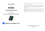
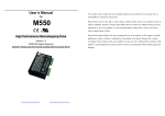
M542 Economical Microstepping Driver Manual V1.0
9. Typical Connection
closest to your motor’s required current.
Dynamic Current Setting
Peak current (A)
1.00
1.46
1.91
2.37
2.84
3.31
3.76
4.20
RMS (A)
0.71
1.04
1.36
1.69
2.03
2.36
2.69
3.00
M542 Economical Microstepping Driver Manual V1.0
SW1
ON
OFF
ON
OFF
ON
OFF
ON
OFF
SW2
ON
ON
OFF
OFF
ON
ON
OFF
OFF
SW3
ON
ON
ON
ON
OFF
OFF
OFF
OFF
A complete stepping system should include stepping motor, stepping driver, power supply and
controller (pulse generator). A typical connection is shown as figure 10.
Notes: Due to motor inductance, the actual current in the coil may be smaller than the dynamic
current setting, particularly under high speed condition.
Standstill Current Setting
SW4 is used for this purpose. OFF meaning that the standstill current is set to be half of the selected
dynamic current, and ON meaning that standstill current is set to be the same as the selected dynamic
current.
The current automatically reduced to 60% of the selected dynamic current 1 second after the last
pulse. Theoretically, this will reduce motor heating to 36% (due to P=I2*R) of the original value. If
the application needs a different standstill current, please contact Leadshine.
8. Wiring Notes
l
In order to improve anti-interference performance of the driver, it is recommended to use
twisted pair shield cable.
l
To prevent noise incurred in PUL/DIR signal, pulse/direction signal wires and motor wires
should not be tied up together. It is better to separate them by at least 10 cm, otherwise the
disturbing signals generated by motor will easily disturb pulse direction signals, causing motor
position error, system instability and other failures.
l
If a power supply serves several drivers, separately connecting the drivers is recommended
instead of daisy-chaining.
l
It is prohibited to pull and plug connector P2 while the driver is powered ON, because there is
high current flowing through motor coils (even when motor is at standstill). Pulling or plugging
connector P2 with power on will cause extremely high back-EMF voltage surge, which may
damage the driver.
Tel: +086 0755-26434369
9
Web Site: www.leadshine.com
Figure 10: Typical connection
10. Sequence Chart of Control Signals
In order to avoid some fault operations and deviations, PUL, DIR and ENA signals must abide by
some rules, as shown in the following diagram (assuming J1 default setting is upward-rising edge
effective):
Figure 11: Sequence chart of control signals
Tel: +086 0755-26434369
10
Web Site: www.leadshine.com
www.yusto.ru
[email protected]