1
PSP SERIES
PSP SERIES
USER MANUAL
CONTENTS
USER MANUAL
PAGE
1. Product Introduction…………..........................................…... 1
2. Safety Information……………………….……………….…... 3
3. Technical Specification………….…………………………….. 7
4. Panel Controls and Indicator………………………….…..…. 9
5. Functional Description of Operation Element……...……….. 12
6. Operating Instruction with Keypad Input............................... 13
7. Disposal......…………………………………………………….. 17
8. Rectification of Faults………….……………………………… 18
9. Maintenance..........……….……………………………………. 19
10. APPENDIX: Connecting the Programmable Power Supply
via RS232 Interface..................................................................... 21
Declaration of Conformity
We
GOOD WILL INSTRUMENT CO., LTD.
No. 95-11, Pao-Chung Rd., Hsin-Tien City, Taipei Hsien, Taiwan
declares that the below mentioned product
PSP-603, PSP-405,
PSP-2010
Are herewith confirmed to comply with the requirements set out in the Council
Directive on the Approximation of the Law of Member States relating to
Electromagnetic Compatibility (89/336/EEC, 92/31/EEC, 93/68/EEC) and Low
Voltage Equipment Directive (73/23/EEC). For the evaluation regarding the
Electromagnetic Compatibility and Low Voltage Equipment Directive, the following
standards were applied:
◎ EMC
EN 61326-1: Electrical equipment for measurement, control and laboratory use ––
EMC requirements (1997+A1: 1998)
Conducted and Radiated Emissions
Electrostatic Discharge
EN 55011: 1998
EN 61000-4-2: 1995+A1:1998
Current Harmonic
Radiated Immunity
EN 61000-3-2: 1995+A1: 1998+A2: 1998
EN 61000-4-3: 1996
Voltage Fluctuation
Electrical Fast Transients
EN 61000-3-3: 1995
EN 61000-4-4: 1995
Surge Immunity
------------------------EN 61000-4-5: 1995
Conducted Susceptibility
------------------------EN 61000-4-6: 1996
P.F.Magnetic Field
------------------------EN 61000-4-8: 1993
Voltage Dips/ Interrupts
------------------------EN 61000-4-11: 1994
◎ Safety
Low Voltage Equipment Directive 73/23/EEC & amended by 93/68/EEC
EN 61010-1: 1993+A2: 1995
IEC 61010-1: 1990+A1: 1992+A2 :1995
EN 60950 :1992+A1:1993+A2 :1993+A3 :1995+A4 : 1997+A11: 1997
IEC 60950:1991+A1:1992+A2 :1993+A3 :1995+A4 : 1996
i
ii
PSP SERIES
PSP SERIES
USER MANUAL
USER MANUAL
SAFETY TERMS AND SYMBOLS
FOR UNITED KINGDOM ONLY
These terms may appear in this manual or on the product:
NOTE: This lead/appliance must only be wired by competent
persons
WARNING. Warning statements identify condition or
practices that could result in injury or loss of life.
WARNING: THIS APPLIANCE MUST BE EARTHED
IMPORTANT: The wires in this lead are coloured in accordance
CAUTION. Caution statements identify conditions or
with the following code:
practices that could result in damage to this product or
other property.
The following symbols may appear in this manual or on the
Green/ Yellow:
Earth
Blue:
Neutral
Brown:
Live (Phase)
product:
As the colours of the wires in main leads may not correspond with
the colours marking identified in your plug/appliance, proceed as
follows:
The wire which is coloured Green & Yellow must be connected to
DANGER
ATTENTION
High Voltage refer to Manual
Protective
Earth (ground) Frame or
the Earth terminal marked with the letter E or by the earth
Conductor
Terminal
symbol
Terminal
Chassis
Terminal
or coloured Green or Green & Yellow.
The wire which is coloured Blue must be connected to the
terminal which is marked with the letter N or coloured Blue or
Black.
iii
iv
PSP SERIES
PSP SERIES
USER MANUAL
The wire which is coloured Brown must be connected to the
USER MANUAL
1. Product Introduction
terminal marked with the letter L or P or coloured Brown or Red.
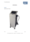
The PSP series is a programmable switching power supply with backlit
liquid crystal display built to the latest technological standards.
If in doubt, consult the instructions provided with the equipment
or contact the supplier.
Construction is in accordance with VDE 0411 = EN 61010. Moreover, the
PSP series has been EMV-tested and fulfils the requirements of the
applicable European and national directives. Conformance to these has
This cable/appliance should be protected by a suitably rated and
approved HBC mains fuse: refer to the rating information on the
equipment and/or user instructions for details. As a guide, cable of
0.75mm2 should be protected by a 3A or 5A fuse. Larger
conductors would normally require 13A types, depending on the
connection method used.
been proven; the relevant statements and documents are lodged with the
manufacturer.
Note: This is a Class A device which can cause RF
interference within the home.
To maintain this condition and to guarantee safe operation, the user
Any moulded mains connector that requires removal /replacement
must be destroyed by removal of any fuse & fuse carrier and
disposed of immediately, as a plug with bared wires is hazardous if
a engaged in live socket. Any re-wiring must be carried out in
accordance with the information detailed on this label.
must observe these operating instructions without fail.
Application Note
z
Connection of low-voltage loads to the marked connection sockets
provided for this purpose and their operation at a voltage between 0 to
rating voltage.
z
The current consumption of a connected load may not exceed rating
current.
z
The Switching Power Supply PSP series is suitable for connection to
115 or 230 V 50/60 Hz AC power sockets.
z
Operation must not take place under unfavorable ambient conditions
including:
-Moisture or excessive air humidity.
-Dust and combustible gases, fumes or solvents.
v
1
PSP SERIES
PSP SERIES
USER MANUAL
-Thunderstorms or storm conditions such as strong electrostatic fields,
etc.
Any use other than above description may leads to damage to the unit;
or causes dangers such as short circuit, fire, electric shock, etc. No part
USER MANUAL
2. Safety Information
Note: Damage caused by failure to observe the operating
instructions voids the guarantee.
of the product may be modified or converted. The safety instructions are
to be followed without fail.
We accept no liability for consequential damage and accept no responsibility
for damage to property or injury to persons caused by improper operation
or failure to observe the safety instructions. Such cases void the guarantee.
a) Installation and handling safety instructions
Observe the following rules when installing the instrument:
a1. Avoid use the instrument in extremely cold or hot locations or
directly adjacent to a heating fan.
a2. Never switch the instrument on immediately when it is brought
from a cold environment into a warm room until the instrument
comes to room temperature as under the adverse conditions, the
resultant condensation may destroy the instrument.
a3. Ensure there is proper ventilation for the vents in the case (front left
side and cooling fan on the rear) to prevent heat build-up from
damaging the instrument.
a4. Never operate the instrument near hot soldering irons.
a5. Do not place the Power Supply with its front panel down to avoid
damaging the operating controls.
b) General safety requirements
The Switching Power Supply PSP series has been fully inspected and
tested with technically safe condition before shipping from the factory.
To maintain this condition and to ensure safe operation, it is essential
for the user to observe the safety instructions and warning notes which
2
3
PSP SERIES
PSP SERIES
USER MANUAL
USER MANUAL
are contained in this user manual.
While proceeding the operation of power supplies, the wearing of
The instrument is constructed to Protection Class I. It is equipped with
metal or other conducting jewelry such as chains, bracelets, rings, etc.
a VDE-approved power supply with safety cable and may only be used
is not recommended.
with and connected to AC supplies with safety earthing.
Ensure that the (yellow/green) earthed wire in the instrument, in its
Note: Power supplies are not intended for use with/on
power cable and in the AC supply remains sound, because a damaged
people or animals.
earth wire can endanger life.
In commercial facilities the accident-prevention regulations of the
When connecting the outputs of more than one power supply in series
industrial employers' liability association for electrical systems and
voltages may danger to life (> 35 VDC). Only power supplies with an
equipment must be observed.
identical output (current and voltage) specification may be placed in
In schools, training facilities, hobby and self-help workshops, the
series or in parallel, otherwise the weaker of the two will be damaged.
operation of power supplies and accessories must be supervised by the
The instrument is to be placed onto a hard, non-inflammable base, so
trained personnel.
that cooling air can enter unhindered. The cooling of the unit occurs
Make sure that only the fuses of the given types and nominal current
predominantly through convection.
ratings are used as replacements. The use of repaired fuses or the
bridging of fuse holders is not permitted. A small flat-bladed
Note: Power supply ventilation holes should not be
screwdriver is required to change the AC fuse. Carefully lever up the
covered.
cover in the AC power socket and withdraw it. Remove the defective
Power supplies and their connected loads should not be left operating
fuse and replace it with an intact one of the same type and nominal
unsupervised. There are measures for the protection and safety of
current rating. Afterwards replace the fuse cover.
connected loads in the face of power supply incidents (e.g.
The measuring instrument is operated only when the case is securely
overvoltages, complete failure) and effects and dangers stemming
closed and screwed up.
from the loads themselves (e.g. unduly-high current consumption).
Faulty power supplies can produce voltages over 50 V DC, which can
be dangerous even when the indicated normal output voltages of the
units are lower than this.
Note: For power-on work, only tools expressly intended
for this should be used.
4
5
PSP SERIES
PSP SERIES
USER MANUAL
The power supply outputs and connecting leads, sockets and terminals
USER MANUAL
3. Technical Specifications
must be protected from being touched directly. In addition, the leads
Model
used must be sufficiently insulated and voltage-proof and the contact
points safe from being touched (safety sockets).
Use of bare metal leads and contacts should be avoided. All such items
are to be covered by suitable, nonflammable insulating material or
other measures taken and therefore protected from being touched
directly. The electrically conducting parts of the connected load must
also be appropriately protected from being touched directly.
Operating voltage
Power frequency
Power consumption
Power output
Output voltage
Program Accuracy
Output Current
If the instrument is assumed that safe operation is no longer possible
according to the following phenomena, then the unit must be switched
off and protected against unintentional operation:
- the unit shows visible signs of damage,
- the unit no longer functions and
- after prolonged storage under unfavourable conditions or
- after severe transportation stress.
Do switch on the switched power supply immediately when it has been
brought from a cold environment into a warm room until it comes to
room temperature as under adverse conditions, the resultant
Program Accuracy
Voltage Load
Regulation
Current Load
Regulation
Voltage Line
Regulation.
Current Line
Regulation
Ripple Voltage
Ripple Current
Readback Resolution
(Meter)
PSP-405
PSP-2010
115/230 VAC ±15%
50/60 Hz
approx. 420VA max.
200W max.
0~60VDC,
0~40VDC,
0~20VDC,
20mV resolution 10mV resolution 10mV resolution
±0.05%±4 digits ±0.05%±3 digits ±0.05%±3 digits
0~3.5A
0~5A
0~10A
2mA resolution 2mA resolution 5mA resolution
±0.1%±5 digits ±0.1%±5 digits ±0.3%±10 digits
≦ 10 mV
≦ 5 mA
≦ 0.05%
≦ 0.05%
≦ 20 mV rms
≦ 10 mArms
20mV 2mA
10mV 2mA
10mV 5mA
Readback Accuracy (Meter)
condensation can destroy the unit.
Voltage
±0.05%±4 digits ±0.05%±3 digits ±0.05%±3 digits
Current
±0.1%±5 digits
Digital Display
AC fuse
Weight
Dimensions
(W × H × L)
6
PSP-603
±0.1%±5 digits ±0.3%±10 digits
Multi-line LCD with background lighting
Slow-blow T6.3A/250V for 115V, T3.15A/250V for 230V
Approx. 4 kgs
Approx. 225×100×305 m/m
(without stand and power cable)
7
PSP SERIES
PSP SERIES
USER MANUAL
USER MANUAL
4. Panel Controls & Indicator
Environmental Conditions
Operating
Environment
Indoor use, altitude up to 2000m.
Ambient Temperature 0℃ to 40℃.
Relative Humidity 80%(Maximum).
Installation category II
Pollution Degree
2
0°C to +40°C
80% (Maximum), non-condensing
-10°C to +70°C
Operating temperature &
Humidity
Storage temperature range
Power cord….............……….. 1
Instruction manual…………… 1
Test Lead……….……………. 1
Accessories
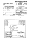
Front Panel
1) 4 mm safety sockets: 1a negative connection "-", 1b positive
connection "+" and 1c earth connection.
2) "POWER" AC switch for switching the power supply on ("1") and
off ("0").
3) Encoder wheel for changing the V SET, V LIMIT, I LIMIT, P
LIMIT, +%, and -% parameter settings.
4) Keypad for actual operation of the Switching Power Supply PSP
series. The exact description follows below.
5) Backlit LCD Display with indication of the output voltage, current,
power settings and indication of the V, I and P limits. Additionally,
indication of OUTPUT On or Off and keypad locked or unlocked.
Rear Panel
6) AC rear power socket.
7) RS-232 interface (with optocoupler) for connection to PC.
8) Cooling fan.
8
9
PSP SERIES
PSP SERIES
USER MANUAL
z
USER MANUAL
z
Front Panel
Rear Panel
Figure 4-2
Figure 4-1
10
11
PSP SERIES
PSP SERIES
USER MANUAL
5. Functional Description of Operating Elements
With its continuously adjustable voltage and current settings, this
USER MANUAL
6. Operating Instructions with keypad input
A) Basic setting
power supply can be used universally in school, work, hobby, and other
a) Connect the AC power cable to the AC power socket and ensure
applications. An electronic current limiter protects the power supply from
that it is firmly seated. Then plug the earthed power plug into an
overload and short-circuits at its output; a fan controlled by a temperature
earthed AC power socket.
circuit protects the power supply (its electronics) from thermal overload.
Attention: The continuity of the safety earth wire must be
During such an overload (short circuit or overload) the output is
unbroken within the instrument, within the AC power
regulated down, i.e. the voltage is reduced. Only when the short-circuit
cable and within the AC power socket otherwise life will
has been remedied is the output released.
be endangered.
The set values can be read via the illuminated multiple-line LCD
b) Press the AC power On/Off switch
display. The voltage, current or power setting is adjusted by means of an
Attention: The earth connector in the front of the
encoder wheel in 10mV, 20mV, 1mA, 2mA, 10mA and 1 W steps
instrument and the RS-232 interface connector earth are
respectively. Therefore the exact adjustment of the output voltage and the
connected directly with the earthing wire of the AC power
current limit and maximum output power is possible. However, observe
input socket and of the connected AC power socket.
the safety hints without fail.
Before operating the instrument each time, first check and ensure
that the 4 mm sockets of the instrument is well fit of no damage.
B) Setting the limits
The voltage, current and power output values are each limited to a
maximum. This upper limit can be varied downwards. Setting the
limits is carried out using the “V LIMIT” “I LIMIT” “P LIMIT”
keys as follows:
V LIMIT Voltage limit
Press the "V LIMIT" key in the "LIMITS" field until
the symbol "U-const" flashes. The voltage limit can now
be adjusted to 1V steps by using the encoder wheel. If
the "V LIMIT " key is now pressed for longer than 2s,
12
13
PSP SERIES
PSP SERIES
USER MANUAL
USER MANUAL
the voltage upper limit will again be set at "rating
complete the input, press the "ENTER" key. An
voltage". To complete the input, press the "ENTER"
inadvertently wrong-set limit setting can be erased/reset
key. An inadvertently wrong-set limit setting can be
with the " CE " key. As a result of this, the previous set
erased/reset with the " CE " key. As a result of this, the
value will be indicated and the setting menu exited. The
previous set value will be indicated and the setting
"P-const" will no longer flash.
menu exited. The "U-const" will no longer flash.
Attention: The current "I LIMIT" is adjusted
During operation (output On), the voltage output can
independently of its setting by the maximum output
also be adjusted up to the set limit.
power setting. The voltage upper limit does not
I LIMIT Current limit
Press the " I LIMIT" key in the "LIMITS" field until the
change.
C) "KEY INPUT" field settings
symbol "I-const" flashes. The current limit can now be
V SET Using the "V SET" key, the output voltage can be adjusted
adjusted to 1mA, 2mA, 10mA ("fine") or 100mA
up to the preset upper limit directly. For this the "V SET"
("norm", coarse) steps by using the encoder wheel. If
key must be pressed and held and the voltage changed
the "I LIMIT" key is now pressed for longer than 2s, the
with the encoder wheel. If the "fine"
current upper limit will again be set at "rating current".
the changes occur in 10 mV, and 20mV steps.
To complete the input, press the "ENTER" key. An
"norm"
inadvertently wrong-set limit setting can be erased/reset
steps.
with the " CE " key. As a result of this, the previous set
key is selected,
If
key is selected, the changes occur in 1V
ENTER Each input via the "LIMITS" keypad is completed with the
value will be indicated and the setting menu exited. The
"I-const" will no longer flash.
N
F
"ENTER" key.
CE
P LIMIT Power limit
Any values incorrectly entered via the "LIMITS" keypad
can be reset with the " CE " key.
Press the "P LIMIT" key in the "LIMITS" field until the
N
symbol "P-const" flashes. The power limit can now be
" N " ("Normal") key. In connection with the " F " key,
adjusted to 1 W steps by using the encoder wheel. If the
"P LIMIT" key is now pressed for longer than 2s, the
power upper limit will again be set at "200 W". To
14
The size of each setting step can be changed by using the
so-called mutual locking is achieved.
F
If the " N " key is pressed, the "fine" symbol disappears from
the display. If the " F " key is pressed, the symbol "fine"
15
PSP SERIES
PSP SERIES
USER MANUAL
appears on the display.
USER MANUAL
For example:
LOCK Pressing the "LOCK" key locks/blocks all keys and the
Set the output voltage as 10.00V, the save value of +% is 105,
encoder wheel against inadvertent adjustment. Only the
and the save value of -% is 95. The +% key is pressed, output
"Power" switch remains active. Locking is indicated by the
voltage will be changed to 10.00V × 1.05 = 10.50V, while the
"locked" symbol in the bottom line of the display. If the
-% key is pressed, output voltage will be changed to 10.00V ×
"LOCK" key is pressed again (> approx. 2s), then the
0.95 = 9.50V. The output voltage will be back to normal by
operating elements are released again (unlocked).
pressing the normal key.
F) "REM" key
D) Adjusting the output
OUTPUT The output of the power supply is switched on or off via
A serial RS-232 interface is incorporated on the rear of the case.
a relay with the "OUTPUT" key. In the process, the
With the appropriate interface cable and optional software,
status "On" or "Off" is indicated at the bottom right of
communication with an IBM-compatible PC is therefore possible.
the display. On switching the power supply on, the
The interface is naturally via an optocoupler.
output is always in switched-off status.
REM Clear the Remote Control mode and use panel control setting
instead. Thereupon, as with "LOCK", all operating elements
E) +%, -% settings
+%
Under output off status, press +% key once, the LCD display
(except POWER) are locked against direct input.
will indicate xxx (the multiple value of the original storage
data), now set the +% value by using the knob and press enter
7. Disposal
key to save it. Afterward, when the output is in the “ON”
Dispose of an unusable, irreparable Switching Power Supply PSP
status, press +% key, the output will be changed according to
series in accordance with applicable statutory regulations.
the saved multiple value.
-%
Under output off status, press -% key once, the LCD display
will indicate xxx (the multiple value of the original storage
data), now set the -% value by using the knob and press enter
key to save it. Afterward, when the output is in the “ON”
status, press -% key, the output will be changed according to
the saved multiple value.
16
17
PSP SERIES
PSP SERIES
USER MANUAL
USER MANUAL
8. Rectification of faults
With the PSP series power supply you have acquired a new generation
9. Maintenance
measuring instrument constructed to the latest technological standards.
However, faults can occur. Because of this, the following describes
how some of these problems can be resolved by the user relatively
The following instructions are executed by qualified personnel only. To avoid
electrical shock, do not perform any servicing other than the operating instructions
unless you are qualified to do so.
easily:
9-1.Fuse Replacement
Problem
Possible solution
No display
Is the instrument switched on?
If the fuse blown, the CV or CC indicators will not light and the
Is the AC power plug making good contact
power supply will not operate. The fuse should not normally blow
both in the instrument and in the AC power
unless a problem has developed in the unit.
socket?
correct cause of the blown fuse, then replace only with a fuse of the
Is the AC fuse OK?
correct rating and type. The fuse is located on the rear panel (see Fig.
"REM" or "LOCK" key pressed; see under
4-2).
No input possible
Try to determine and
section C or F
WARNING: For continued fire protection. Replace with
Attention: Except when this is possible manually, the opening
of covers or removal of parts can expose voltage-carrying
components. Connection points may also be live. Before any
adjustment, maintenance, repair or exchange of parts or
assemblies requiring opening of the unit, the unit must be
disconnected from all voltage sources and measurement
circuits. If the adjustment maintenance or repair is
subsequently required for the open unit, these must only be
performed by a specialist familiar with the associated
hazards and relevant regulations (VDE-0100, VDE-0701,
VDE0683).
Capacitors within t he instrument can remain charged
even when the unit has been disconnected from all voltage
sources and measurement circuits.
250V fuse of the specified type and rating, and disconnect
the power cord before replacing fuse.
9-2.Line Voltage conversion
The primary winding of the power transformer is tapped to permit
operation from 115/230 VAC, 50/60 Hz line voltage. Conversion from
one line voltage to another is done by change AC selects switch as
shown in Fig. 4-2.
To convert to different line voltage, perform the following procedure:
(1) Make sure the power cord is unplugged.
(2) Set the AC switch to the desired line voltage position.
18
19
PSP SERIES
PSP SERIES
USER MANUAL
USER MANUAL
9-3. Cleaning
To clean the power supply, use a soft cloth dampened in a solution
of mild detergent and water. Do not spray cleaner directly onto
the instrument, since it may leak into the cabinet and cause
damage.
Do not use chemicals containing benzine, benzene,
toluene, xylene, acetone, or similar solvents. Do not use abrasive
cleaners on any portion of the instrument.
9-4. Fan Control
1) The fan of the power supply will not work upon power on
until the temperature or load current reaches the condition as
follows:
z Temperature oriented:
When the temperature of the power supply reaches to range
of 45℃±5℃ for 5 to 6 seconds, the fan starts to work,
while the temperature is less than 40℃±5℃, the fan stops
rolling.
z Load current oriented:
The load current varies with different model of power supplies.
After the load current reaches to the value as shown below, the
fan will keep on rolling.
Model
Load Current
Fan Load Current Fan
PSP-405
2.10A±50mA
On 1.80A±50mA Off
PSP-603
1.40A±50mA
On
1.20A±50mA Off
PSP-2010
2.10A±50mA
On
1.80A±50mA Off
10. APPENDIX: Connecting the Programmable Power
Supply via RS232 Interface
The RS232 interface capabilities:
The RS232 interface provides a point-to-point connection between two
items of equipment such as a computer and the power supply. There
are some parameters you need to set on the both sides. Once you have
set these parameters, you can control the power supply through the
RS232 interface.
z
Baud rate: 2400 baud.
z
Parity bit: none.
z
Data bit: 8 bits.
z
Stop bit: 1 stop bit.
z
Data flow control: none.
Notes for RS232 installation
The power supply is a DTE device with a 9-pin D-type shell RS232
connector located on the rear panel. Figure 1 shows the equipment of
9-pin connector (Male) with its pin number assignments. Figure 2
shows the wiring configuration for DB9 to DB9. When the
programmable power supply is set up with a RS232 interface, please
check the following points:
z
z
z
z
z
z
z
Do not connect the output line of one DTE device to the output
line of the other.
Many devices require a constant high signal on one or more input
pins.
Ensure that the signal ground of the equipment is connected to
the signal ground of the external device.
Ensure that the chassis ground of the equipment is connected to
the chassis ground of the external device.
Do not use more than 15m of cable to connect devices to a PC.
Ensure the same baud rate is used on the device as the one used
on PC terminal.
Ensure the connector for the both side of cable and the internal
connected line are met the demand of the instrument.
2) To avoid damaging the power supply, if the fan failed to work
when the temperature or current has reached to the specific
condition, please power off the instrument and contact our local
distributor for service.
20
21
PSP SERIES
PSP SERIES
USER MANUAL
1.
2.
3.
4.
5.
6.
7.
8.
9.
USER MANUAL
No connection
Receive Data(RxD)
(input)
Transmit Data(TxD) (output)
+12V Input(*)
(input)
Signal Ground(GND)
No connection
No connection
No connection
No connection
*Note: This pin needs a constant high signal (+12V).
Figure 1 Pin assignments of the RS232 connector on the rear panel for DB-9-D
EQUIPMENT
COMPUTER
(DB9, DTE)
(DB9, DTE)
Pin 2
Pin 2
Pin 3
Pin 3
Pin 4
Pin 4
Pin 5
Pin 5
Figure 2 Wiring configuration for DB9 to DB9
Computer’s Connection
A personal computer with a COM port is the essential facilities in
order to operate the programmable power supply via RS232 interface.
The connections between power supply and computer are as follows:
I.
II.
III.
IV.
RS232 message terminator
The power supply has 25 commands available. Every command is end
up with <cr> (ASCII 0Dh or ACSCII 0D 0A acceptable). The return
message <cr>of the power supply is CR/LF (ASCII 0D 0A).
*L
Function:
To obtain all the status values of the power supply.
Syntax:
L<cr>
HEX = 4C 0D
Explain:
When the message L<cr>is sent to the power supply from computer,
the power supply will return the message as follows immediately:
Vvv.vvAa.aaaWwww.wUuuIi.iiPpppFffffff<cr> 37 characters
totally
The contents consist of the uppercase V,A,W,U,I,P,F, the numeral
from 0 to 9 and decimal. Further details is described as follows:
vv.vv
= The present output voltage, the unit: V.
a.aaa
= The present output current, the unit: A.
www.w
= The present output load, the unit: W.
uu
= The maximum voltage limit at present, the unit: V.
i.ii
= The maximum current limit at present, the unit: A.
ppp
= The maximum load limit at present, the unit: W.
Connect one end of a RS232 cable to the computer.
Connect the other end of the cable to the RS232 port on the
programmable power supply.
Turn on the programmable power supply.
Turn on the computer.
22
23
PSP SERIES
PSP SERIES
USER MANUAL
ffffff
USER MANUAL
= The status of power supply at present.
st
1 f = the relay status 0: OFF
F101000
1:ON
2nd f = the temperature status 0: Normal
rd
3 f = the wheel knob status 0: Normal
1: Overheat
Not yet getting into Lock mode.
1: Fine
Not yet getting into Remote mode.
4th f = the wheel knob status 0: Lock 1: Unlock
th
5 f = the remote status 0: Normal
6th f = the lock status
Wheel knob setting acceptable (this signal can
be ignored)
1: Remote(*)
Wheel knob is in the Fine mode.
0: Unlock 1: Lock
The temperature isn’t overheat.
*Note: The setting is workable through computer only when the
remote is at 1.
Relay on.
All the data above is in the range from 0 to 9.
When the uppercase U becoming the lowercase u means that the status
is in the setting of the voltage limit mode.
When the uppercase I becoming the lowercase i means that the status
is in the setting of the current limit mode.
When the uppercase P becoming the lowercase p means that the status
is in the setting of the load limit mode.
Example:
The return message from power supply is:
V20.00A2.500W050.0U40I5.00P200F101000<cr>
*V
Function:
The present output voltage, the unit is V.
Syntax:
V<cr>
HEX = 56 0D
Explain:
When the message of V<cr>is sent to the power supply from computer,
the power supply will return the following message immediately:
Vvv.vv<cr> 6 characters totally + CR/LF
V20.00 means that the present output voltage is at 20.00V.
A2.500 means that the present output current is at 2.500A.
W050.0 means that the present output load is at 050.0W.
U40 means that the present voltage limit is at 40V.
The contents consist of the uppercase V, the numeral from 0 to 9 and
decimal. Further details is described as follows:
vv.vv = The present output voltage, the unit: V
15.00 means that the present current limit is at 5.00A.
P200 means that the present load limit is at 200W.
24
25
PSP SERIES
PSP SERIES
USER MANUAL
USER MANUAL
*A
*U
Function:
Function:
The present output current, the unit is A.
The maximum voltage limit at present, the unit is V.
Syntax:
A<cr>
HEX = 41 0D
Explain:
When the message of A<cr>is sent to the power supply from computer,
the power supply will return the following message immediately:
Syntax:
U<cr>
HEX = 55 0D
Explain:
When the message of U<cr> is sent to the power supply from
computer, the power supply will return the following message
immediately:
Aa.aaa<cr> 6 characters totally + CR/LF
Uuu<cr> 3 characters totally + CR/LF
The contents consist of the uppercase A, the numeral from 0 to 9 and
decimal. Further details is described as follows:
The contents consist of the uppercase U and the numeral from 0 to 9.
Further details is described as follows:
a.aaa = The present output current, the unit: A
uu = The maximum voltage limit at present, the unit: V
*W
When the uppercase U becoming the lowercase u means that the
power supply is in the setting status of voltage limit mode.
Function:
The present output load, the unit is W.
Syntax:
W<cr>
HEX = 57 0D
Explain:
When the message of W<cr>is sent to the power supply from
computer, the power supply will return the following message
immediately:
Wwww.w<cr> 6 characters totally + CR/LF
The contents consist of the uppercase W, the numeral from 0 to 9 and
decimal. Further details is described as follows:
www.w = The present output load, the unit: W
26
*I
Function:
The maximum current limit at present, the unit is A.
Syntax:
I<cr>
HEX = 49 0D
Explain:
When the message of I<cr>is sent to the power supply from computer,
the power supply will return the following message immediately:
Ii.iii<cr> 5 characters totally + CR/LF
The contents consist of the uppercase I, the numeral from 0 to 9 and
27
PSP SERIES
PSP SERIES
USER MANUAL
decimal. Further details is described as follows:
USER MANUAL
When the message of F<cr> is sent to the power supply from computer,
the power supply will return the following message immediately:
i.ii = The maximum current limit at present, the unit: A
Fffffff<cr> 7 characters totally + CR/LF
When the uppercase U becoming the lowercase u means that the
power supply is in the setting status of current limit mode.
∣∣∣∣∣∣
123446
*P
Function:
The maximum output load limit at present, the unit is W.
The contents consist of the uppercase F and the numeral from 0 to 9.
Further details is described as follows:
1st f = the relay status 0:OFF 1:ON
Syntax:
L<cr>
HEX = 50 0D
Explain:
When the message of L<cr>is sent to the power supply from computer,
the power supply will return the following message immediately:
2nd f = the temperature status 0: Normal
rd
3 f = the wheel knob status 0: Normal
Pppp<cr> 4 characters totally + CR/LF
ppp = The maximum load limit at present, the unit: W
1: Fine
4th f = the wheel knob status 0: Lock 1: Unlock
5th f = the remote status 0: Normal
The contents consist of the uppercase P and the numeral from 0 to 9.
Further details is described as follows:
1: Overheat
6th f = the lock status
1: Remote(*)
0: Unlock 1: Lock
*Note: The setting is workable through computer only when the
remote is at 1.
*SV+
Function:
When the uppercase P becoming the lowercase p means that the power
supply is in the setting status of output load limit mode.
*F
Function:
The present status of the power supply.
Syntax:
F<cr>
Explain:
Add one unit to the present voltage setting.
Syntax:
SV+<cr>
HEX = 53 56 2B 0D
Explain:
When the message of SV+<cr> is sent to the power supply from
computer, the power supply will add one unit to the present voltage
setting immediately.
HEX = 46 0D
28
29
PSP SERIES
PSP SERIES
USER MANUAL
USER MANUAL
Example:
Example:
The present output voltage is at 20.00V, and the wheel knob status is
at normal, the SV+<cr> message is sent to the power supply, the
voltage of which will become 21.00V.
The present voltage limit is at 30V, and the wheel knob status is at
normal, the SV+<cr> message is sent to the power supply, the voltage
limit of which will become 31V.
*SV-
*SU-
Function:
Function:
Subtract one unit from the present voltage setting.
Subtract one unit from the present voltage limit setting.
Syntax:
SV-<cr>
HEX = 53 56 2D 0D
Explain:
When the message of SV-<cr> is sent to the power supply from
computer, the power supply will subtract one unit from the present
voltage setting immediately.
Syntax:
SU-<cr>
HEX = 53 55 2D 0D
Explain:
When the message of SU-<cr> is sent to the power supply from
computer, the power supply will subtract one unit from the present
voltage limit setting immediately.
Example:
The present output voltage is at 20.00V, and the wheel knob status is
at normal, the SV-<cr> message is sent to the power supply, the
voltage of which will become 19.00V.
*SU+
Function:
Add one unit to the present voltage limit setting.
Syntax:
SU+<cr>
HEX = 53 55 2B 0D
Explain:
When the message of SU+<cr> is sent to the power supply from
computer, the power supply will add one unit to the present voltage
limit setting immediately.
30
31
PSP SERIES
PSP SERIES
USER MANUAL
USER MANUAL
Example:
Example:
The present voltage limit is at 30V, and the wheel knob status is at
normal, the SU-<cr> message is sent to the power supply, the voltage
limit of which will become 29V.
The present current limit is at 3.00A, and the wheel knob status is at
normal, the SI-<cr> message is sent to the power supply, the current
limit of which will become 2.90A.
*SI+
*SP+
Function:
Function:
Add one unit to the present current limit setting.
Add one unit to the present load limit setting.
Syntax:
SI+<cr>
HEX = 53 49 2B 0D
Explain:
When the message of SI+<cr> is sent to the power supply from
computer, the power supply will add one unit to the present current
limit setting immediately.
Syntax:
SP+<cr>
HEX = 53 50 2B 0D
Explain:
When the message of SP+<cr> is sent to the power supply from
computer, the power supply will add one unit to the present load limit
setting immediately.
Example:
Example:
The present current limit is at 3.00A, and the wheel knob status is at
normal, the SI+<cr> message is sent to the power supply, the current
limit of which will become 3.10A.
The present load limit is at 100W, and the wheel knob status is at
normal, the SP+<cr> message is sent to the power supply, the load
limit of which will become 101W.
*SI-
*SP-
Function:
Function:
Subtract one unit from the present current limit setting.
Subtract one unit from the present load limit setting.
Syntax:
SI-<cr>
HEX = 53 49 2D 0D
Explain:
When the message of SI-<cr> is sent to the power supply from
computer, the power supply will subtract one unit from the present
current limit setting immediately.
Syntax:
SP-<cr>
HEX = 53 50 2D 0D
Explain:
When the message of SP-<cr> is sent to the power supply from
computer, the power supply will subtract one unit from the present
load limit setting immediately.
32
33
PSP SERIES
PSP SERIES
USER MANUAL
USER MANUAL
Example:
Example:
The present load limit is at 100W, and the wheel knob status is at
normal, the SP-<cr> message is sent to the power supply, the load
limit of which will become 099W.
The present current limit is at 2.50A, the SIM<cr> message is sent to
the power supply, the current limit of which will become 5.00A.
*SPM
*SUM
Function:
Function:
Set the maximum load limit value.
Set the maximum voltage limit value.
Syntax:
SUM<cr>
HEX = 53 55 4D 0D
Explain:
When the message of SUM<cr> is sent to the power supply from
computer, the power supply will set the voltage limit to the maximum
immediately.
Syntax:
SPM<cr>
HEX = 53 50 4D 0D
Explain:
When the message of SPM<cr> is sent to the power supply from
computer, the power supply will set the load limit to the maximum
immediately.
Example:
Example:
The present voltage limit is at 20V, the SUM<cr> message is sent to
the power supply, the voltage limit of which will become 40V.
The present load limit is at 100W, the SPM<cr> message is sent to the
power supply, the load limit of which will become 200W.
*KF
*SIM
Function:
Function:
Set the wheel knob to Fine status.
Set the maximum current limit value.
Syntax:
SIM<cr>
HEX = 53 49 4D 0D
Explain:
When the message of SIM<cr> is sent to the power supply from
computer, the power supply will set the current limit to the maximum
immediately.
Syntax:
KF<cr>
HEX = 4B 46 0D
Explain:
When the message of KF<cr> is sent to the power supply from
computer, the power supply will set the wheel knob to Fine status
immediately.
Example:
The present wheel knob status is at Normal, the KF<cr> message is
34
35
PSP SERIES
PSP SERIES
USER MANUAL
sent to the power supply, the wheel knob status will become Fine.
USER MANUAL
*KOE
Function:
*KN
Set the Relay status to ON.
Function:
Set the wheel knob to Normal status.
Syntax:
KF<cr>
HEX = 4B 4E 0D
Explain:
When the message of KN<cr> is sent to the power supply from
computer, the power supply will set the wheel knob to Normal status
immediately.
Syntax:
KOE<cr>
HEX = 4B 4F 45 0D
Explain:
When the message of KOE<cr> is sent to the power supply from
computer, whatever the relay status is, the relay of power supply will
be set to ON immediately.
*KOD
Example:
Function:
The present wheel knob status is at Fine, the KN<cr> message is sent
to the power supply, the wheel knob status will become Normal.
Set the Relay status to OFF.
*KO
Function:
Set the Relay status to Invert.
Syntax:
KO<cr>
HEX = 4B 4F 0D
Explain:
When the message of KO<cr> is sent to the power supply from
computer, the power supply will invert the relay status immediately.
Example:
The present relay status is at OFF, the KO<cr> message is sent to the
power supply, the relay status will become ON, send the message
again will become OFF.
36
Syntax:
KOD<cr>
Explain:
HEX = 4B 4F 44 0D
When the message of KOD<cr> is sent to the power supply from
computer, whatever the relay status is, the relay of power supply will
be set to OFF immediately.
*EEP
Function:
Save the present status to the EEPROM.
Syntax:
EEP<cr>
Explain:
HEX = 45 45 50 0D
When the message of EEP<cr> is sent to the power supply from
computer, the power supply will be save the present setting value to
EEPROM immediately.
37
PSP SERIES
PSP SERIES
USER MANUAL
USER MANUAL
*B
Explain:
Function:
To obtain +% value.
Syntax:
B<cr>
When the message of D<cr> is sent to the power supply from
computer, the power supply will return the following message
immediately
HEX = 42 0D
4 characters totally +CR/LF
Explain:
Dddd<cr>
When the message of B<cr> is sent to the power supply from
computer, the power supply will return the following message
immediately
The contents consist of the uppercase D, and the numeral from 0 to 9.
Further details is described as follows:
ddd = The present -% value, the unit: %
Bbbb<cr>
4 characters totally +CR/LF
The contents consist of the uppercase B, and the numeral from 0 to 9.
Further details is described as follows:
bbb = The present +% value, the unit: %
When the uppercase B becoming the lowercase b means that the status
is in the setting of the +% mode.
When the uppercase D becoming the lowercase d means that the status
is in the setting of the -% mode.
*Q
Function:
Display the present value at +% or -% mode.
Syntax:
Q<cr>
HEX = 51 0D
*D
Explain:
Function:
To obtain -% value.
Syntax:
D<cr>
When the message of Q<cr> is sent to the power supply from
computer, the power supply will return the following message
immediately
HEX = 44 0D
Qqqqqqq<cr>
38
7 characters totally +CR/LF
39
PSP SERIES
PSP SERIES
USER MANUAL
USER MANUAL
The contents consist of the uppercase B, and the numeral 0 or 1.
Further details is described as follows:
Whether the first q is at % mode?
0: No
Whether the second q is at +% mode?
1:Yes
0: No
1: Yes
Explain:
When the message of SD-<cr> is sent to the power supply from
computer, the power supply will decrease one unit from the present
setting of +% immediately
Example:
*SB+
Function:
To add one unit to the present setting of +%.
Syntax:
SB+<cr>
The present +% value is at 105, after the command is sent from
computer, the +% value is at 104.
HEX = 53 42 2B 0D
*SD+
Explain:
Function:
When the message of SB+<cr> is sent to the power supply from
computer, the power supply will add one unit to the present setting of
+% immediately
Example:
To add one unit to the present setting of -%.
Syntax:
SD+<cr>
HEX = 53 44 2B 0D
Explain:
The present +% value is at 105, after the command is sent from
computer, the +% value is at 106.
When the message of SD+<cr> is sent to the power supply from
computer, the power supply will add one unit to the present setting of
-% immediately
Example:
*SBFunction:
To decrease one unit from the present setting of +%.
Syntax:
SB-<cr>
The present -% value is at 90, after the command is sent from
computer, the -% value is at 91.
HEX = 53 42 2D 0D
40
41
PSP SERIES
PSP SERIES
USER MANUAL
Example:
*SDFunction:
SV 12.34
To decrease one unit from the present setting of -%.
Syntax:
SD-<cr>
USER MANUAL
Set output voltage to 12.34V
HEX = 53 44 2D 0D
*SU
Explain:
Function:
When the message of SD-<cr> is sent to the power supply from
computer, the power supply will decrease one unit from the present
setting of -% immediately
Example:
The present -% value is at 90, after the command is sent from
computer, the -% value is at 89.
Set voltage limit.
Syntax:
SU xx
x is a number between 0 and 9.
Explain:
The power supply will set desired up-limit value of the voltage when
the command is received.
Example:
*SV
Function:
SU 20
Set the output voltage value.
Set voltage limit to 20V
Syntax:
SV xx.xx
x is a number between 0 and 9.
*SI
Explain:
Function:
The power supply will set the desired value of output voltage when the
command is received.
42
Set current limit.
Syntax:
SI x.xx
x is a number between 0 and 9.
43
PSP SERIES
USER MANUAL
Explain:
The power supply will set desired up-limit value of the current when
the command is received.
Example:
SU 1.25
Set current limit to 1.25A
*SP
Function:
Set power limit.
Syntax:
SP xxx
x is a number between 0 and 9.
Explain:
The power supply will set desired up-limit value of the power when
the command is received.
Example:
SP 100
Set power limit to 100W
**The power setting changes the current limit only, the voltage
limit will remain unchanged.**
44


![[ TVS M ASCOT USER M ANUAL ] - TVS-E](http://vs1.manualzilla.com/store/data/005862685_1-4bbb7317613bf954ee62497b52c82516-150x150.png)