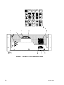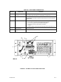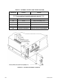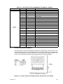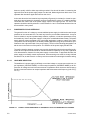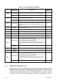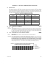
1
OPERATOR MANUAL
ATE-DMG SERIES
POWER SUPPLY
MODELS
KEPCO INC.
An ISO 9001 Company.
ATE 6-100DMG, ATE 15-50DMG,
ATE 25-40DMG, ATE 36-30DMG,
ATE 55-20DMG, ATE 75-15DMG,
ATE 100-10DMG, ATE 150-7DMG
ORDER NO.
REV. NO.
IMPORTANT NOTES:
1)
This manual is valid for the following Model and associated serial numbers:
MODEL
SERIAL NO.
REV. NO.
2)
A Change Page may be included at the end of the manual. All applicable changes and
revision number changes are documented with reference to the equipment serial numbers. Before using this Instruction Manual, check your equipment serial number to identify
your model. If in doubt, contact your nearest Kepco Representative, or the Kepco Documentation Office in New York, (718) 461-7000, requesting the correct revision for your
particular model and serial number.
3)
The contents of this manual are protected by copyright. Reproduction of any part can be
made only with the specific written permission of Kepco, Inc.
Data subject to change without notice.
©2013, KEPCO, INC,
P/N 243-1324b
KEPCO®
THE POWER SUPPLIER™
KEPCO, INC. ! 131-38 SANFORD AVENUE ! FLUSHING, NY. 11355 U.S.A. ! TEL (718) 461-7000 ! FAX (718) 767-1102
email: [email protected] ! World Wide Web: http://www.kepcopower.com
Declaration of Conformity
Application of Council directives:
73/23/EEC (LVD)
93/68/EEC (CE mark)
Standard to which Conformity is declared:
EN61010-1:2001
(Safety requirements for electrical equipment for measurement,
control and laboratory use - Part 1)
Manufacturer's Name and Address:
KEPCO INC.
131-38 SANFORD AVENUE
FLUSHING, N.Y. 11355 USA
Importer's Name and Address:
OPY
C
E
V
I
T
A
T
N
REPRESE
Type of Equipment:
Component Power Supply
Model No.:
[PRODUCT MODEL NUMBER]
Year of Manufacture:
I, the undersigned, declare that the product specified above, when used in conjunction with the conditions of conformance set forth in the product instruction manual, complies with the requirements of the
Low Voltage Directive 73/23/EEC, which forms the basis for application of the CE Mark to this product.
Place:
KEPCO Inc.
131-38 Sanford Ave.
Flushing, N.Y.11355 USA
Saul Kupferberg
(Full Name)
Date:
228-1348 DC-COMP/INST 020613
VP OF SALES
(position)
A
Conditions of Conformance
When this product is used in applications governed by the requirements of the EEC, the following restrictions and conditions apply:
1. For European applications, requiring compliance to the Low Voltage Directive, 73/23/EEC, this power
supply is considered a component product, designed for “built in“ applications. Because it is incomplete in construction, the end product enclosure must provide for compliance to any remaining electrical safety requirements and act as a fire enclosure. (EN61010-1:2001, Cl. 6, Cl. 7, Cl.8, and Cl. 9)
2. This power supply is designed for stationary installation, with mains power applied via a detachable
power supply cord or via direct wiring to the source power terminal block.
3. This power supply is considered a Class 1 (earthed) product. It is intended for use as part of equipment meant for test, measurement and laboratory use, and is designed to operate from single phase,
three wire power systems. This equipment must be installed within a suitably wired equipment rack,
utilizing a three wire (grounded) mains connection. See wiring section of this manual for complete
electrical wiring instructions. (EN61010-1:2001, Cl.6.10.1)
4. This power supply has secondary output circuits that are considered hazardous, and which exceed
240 VA at a potential of 2V or more.
5. The output wiring terminals of this power supply has not been evaluated for field wiring and, therefore,
must be properly configured by the end product manufacturer prior to use.
6. This power supply employs a supplementary circuit protector in the form of a circuit breaker mounted
on the front panel. This circuit breaker protects the power supply itself from damage in the event of a
fault condition. For complete circuit protection of the end product, as well as the building wiring, it is
required that a primary circuit protection device be fitted to the branch circuit wiring. (EN61010-1:2001,
Cl. 9.5)
7. Hazardous voltages are present within this power supply during normal operation. All operator adjustments to the product are made via externally accessible switches, controls and signal lines as specified within the product operating instructions. There are no user or operator serviceable parts within
the product enclosure. Refer all servicing to qualified and trained Kepco service technicians.
B
228-1351 COND/CONFORM 020613
SAFETY INSTRUCTIONS
1. Installation, Operation and Service Precautions
This product is designed for use in accordance with EN 61010-1 and UL 3101 for Installation Category 2,
Pollution Degree 2. Hazardous voltages are present within this product during normal operation. The product should never be operated with the cover removed unless equivalent protection of the operator from
accidental contact with hazardous internal voltages is provided:
!
There are no operator serviceable parts or adjustments within the product enclosure.
Refer all servicing to trained service technician.
!
Source power must be removed from the product prior to performing any servicing.
!
This product is factory-wired for the nominal a-c mains voltage indicated on the rating nameplate located adjacent to the source power connection on the product's rear
panel. To reconfigure the product input for other nominal mains voltages as listed
herein, the product must be modified by a trained service technician.
2. Grounding
This product is a Class 1 device which utilizes protective earthing to ensure operator safety.
!
The PROTECTIVE EARTHING CONDUCTOR TERMINAL must be properly connected prior to application of source power to the product (see instructions on installation herein) in order to ensure safety from electric shock.
PROTECTIVE EARTHING CONDUCTOR TERMINAL - This symbol indicates the
point on the product to which the protective earthing conductor must be attached.
EARTH (GROUND) TERMINAL - This symbol is used to indicate a point which is
connected to the PROTECTIVE EARTHING TERMINAL. The component installer/
assembler must ensure that this point is connected to the PROTECTIVE EARTHING TERMINAL.
CHASSIS TERMINAL -This symbol indicates frame (chassis) connection, which is
supplied as a point of convenience for performance purposes (see instructions on
grounding herein). This is not to be confused with the protective earthing point, and
may not be used in place of it.
3. Electric Shock Hazards
This product outputs hazardous voltage and energy levels as a function of normal operation. Operators
must be trained in its use and exercise caution as well as common sense during use to prevent accidental
shock.
This symbol appears adjacent to any external terminals at which hazardous voltage
levels as high as 500V d-c may exist in the course of normal or single fault conditions.
!
This symbol appears adjacent to any external terminals at which hazardous voltage
levels in excess of 500V d-c may exist in the course of normal or single fault conditions.
228-1352 SAFETY - (COVER REMOVAL) 020613
C/(D BLANK)
TABLE OF CONTENTS
SECTION
PAGE
SECTION 1 - INTRODUCTION
1.1
1.2
1.3
1.4
1.5
1.6
1.6.1
1.6.1.1
1.6.1.2
1.6.2
1.6.3
1.7
1.8
1.9
Scope of Manual ..................................................................................................................................... 1-1
General Description................................................................................................................................. 1-1
Specifications .......................................................................................................................................... 1-1
Local Control ........................................................................................................................................... 1-1
Remote Control ....................................................................................................................................... 1-1
Features .................................................................................................................................................. 1-5
Overvoltage/Overcurrent Protection .................................................................................................. 1-5
Programmable Overvoltage/Overcurrent Delay........................................................................... 1-5
Crowbar Circuit ............................................................................................................................ 1-6
Non-volatile Storage of Programmed Sequences or Active Settings ................................................ 1-6
User-defined Voltage/Current Limits.................................................................................................. 1-6
Equipment Supplied ................................................................................................................................ 1-6
Accessories ............................................................................................................................................. 1-6
Safety ...................................................................................................................................................... 1-6
SECTION 2 - INSTALLATION
2.1
2.2
2.3
2.4
2.5
2.6
2.6.1
2.6.1.1
2.6.1.2
2.7
2.7.1
2.7.2
2.7.3
2.7.4
2.8
Unpacking and Inspection ....................................................................................................................... 2-1
Terminations and Controls ...................................................................................................................... 2-1
Source Power Requirements .................................................................................................................. 2-5
Cooling .................................................................................................................................................... 2-6
Preliminary Operational Check................................................................................................................ 2-6
Installation ............................................................................................................................................... 2-7
Grounding .......................................................................................................................................... 2-7
A-C (Safety) Ground .................................................................................................................... 2-7
Isolation from Ground. ................................................................................................................. 2-7
Fast Mode Conversion of the Ate Power Supply..................................................................................... 2-7
Precautions........................................................................................................................................ 2-8
Lag Network Adjustment.................................................................................................................... 2-8
Crowbar Operation, Fast Mode ......................................................................................................... 2-8
Manual Change-over, Slow/fast Mode............................................................................................... 2-8
Operating Configuration .......................................................................................................................... 2-9
SECTION 3 - OPERATION
3.1
3.1.1
3.1.2
3.1.3
3.1.3.1
3.2
3.2.1
3.2.2
3.2.3
3.2.4
3.3
3.3.1
3.4
3.4.1
3.4.1.1
3.4.1.2
3.4.1.3
3.4.1.4
3.4.2
3.4.3
3.4.4
3.4.5
3.4.6
General.................................................................................................................................................... 3-1
Safety Grounding............................................................................................................................... 3-1
D-C (Output) Grounding .................................................................................................................... 3-1
Power Supply/Load Interface............................................................................................................. 3-2
Load Wire Selection..................................................................................................................... 3-2
Load Connection ..................................................................................................................................... 3-3
General .............................................................................................................................................. 3-3
Load Connection, Method I (Local Error Sensing)............................................................................. 3-4
Load Connection, Method II (Remote Error Sensing)........................................................................ 3-5
Load Connection, Method III.............................................................................................................. 3-6
Overvoltage Crowbar, Setup and Check ................................................................................................. 3-7
Setup and Check Procedure.............................................................................................................. 3-7
Local Mode Operation (Keypad Operation)............................................................................................. 3-7
Front Panel Keypad and LCD............................................................................................................ 3-8
Command Entry Status................................................................................................................ 3-8
Data Entry Status......................................................................................................................... 3-8
Display (LCD)............................................................................................................................... 3-8
Keypad Functions ........................................................................................................................ 3-8
Turning the Power Supply On............................................................................................................ 3-10
Setting Local Mode ............................................................................................................................ 3-11
Adjusting LCD Contrast ..................................................................................................................... 3-11
Enabling/Disabling Audible Beeps..................................................................................................... 3-11
Enabling/Disabling DC Output Power................................................................................................ 3-11
ATE-DMG020613
i
TABLE OF CONTENTS
SECTION
PAGE
3.4.7
Reset................................................................................................................................................. 3-11
3.4.8
Setting Output Voltage or Current..................................................................................................... 3-12
3.4.9
Setting Overvoltage or Overcurrent Protection ................................................................................. 3-12
3.4.10
Changing Protection Delay ............................................................................................................... 3-13
3.4.11
Changing Maximum Voltage or Current Value ................................................................................. 3-13
3.4.12
Storing Power Supply Output Settings.............................................................................................. 3-13
3.4.13
Recalling Stored Output Settings...................................................................................................... 3-14
3.4.14
Enabling Remote Analog Control...................................................................................................... 3-14
3.4.15
Local Mode Programming of the Power Supply................................................................................ 3-14
3.4.15.1
Creating or Modifying a Program (Program Edit Mode).............................................................. 3-14
3.4.15.1.1
Modifying Programmed Time Interval..................................................................................... 3-14
3.4.15.1.2
Time Interval Accuracy........................................................................................................... 3-15
3.4.15.1.3
Display Program Option ......................................................................................................... 3-15
3.4.15.2
Running a Program ..................................................................................................................... 3-15
3.4.15.3
Stepping Through a Program...................................................................................................... 3-15
3.4.15.4
Cycling a Program....................................................................................................................... 3-15
3.4.15.5
Running a Program Once ........................................................................................................... 3-17
3.4.15.6
Stopping a Program .................................................................................................................... 3-17
3.4.15.7
Stopping a Running Program...................................................................................................... 3-17
3.4.15.8
Sample Program ......................................................................................................................... 3-17
3.4.16
Calibration......................................................................................................................................... 3-17
3.5
Analog Remote Programming ................................................................................................................ 3-18
3.6
Digital Remote Mode Programming........................................................................................................ 3-19
3.6.1
IEEE 488 (GPIB) Bus Protocol ......................................................................................................... 3-19
3.6.2
DCL Control ...................................................................................................................................... 3-21
3.6.3
Changing the GPIB Address............................................................................................................. 3-21
3.6.4
Enabling Remote Analog Control...................................................................................................... 3-21
3.6.5
Programming Techniques to Optimize performance ........................................................................ 3-21
3.7
SCPI Programming................................................................................................................................. 3-22
3.7.1
SCPI Messages ................................................................................................................................ 3-22
3.7.2
Common Commands/Queries .......................................................................................................... 3-22
3.7.3
SCPI Subsystem Command/Query Structure................................................................................... 3-22
3.7.3.1
ABORt Subsystem ...................................................................................................................... 3-23
3.7.3.2
DIAG Subsystem......................................................................................................................... 3-23
3.7.3.3
DISPlay Subsystem .................................................................................................................... 3-23
3.7.3.4
INITiate Subsystem..................................................................................................................... 3-23
3.7.3.5
LIST Subsystem.......................................................................................................................... 3-23
3.7.3.6
MEASure Subsystem .................................................................................................................. 3-23
3.7.3.7
OUTPut Subsystem .................................................................................................................... 3-23
3.7.3.8
Protection Subsystem ................................................................................................................. 3-23
3.7.3.9
STATus Subsystem .................................................................................................................... 3-23
3.7.3.10
TRIGger subsystem .................................................................................................................... 3-24
3.7.3.11
[SOURce:]VOLTage and [SOURce:]CURRent Subsystems ...................................................... 3-24
3.7.3.12
CALibrate Subsystem ................................................................................................................. 3-24
3.7.4
Program Message Structure ............................................................................................................. 3-24
3.7.4.1
Keyword ...................................................................................................................................... 3-26
3.7.4.2
Keyword Separator ..................................................................................................................... 3-27
3.7.4.3
Query Indicator............................................................................................................................ 3-27
3.7.4.4
Data............................................................................................................................................. 3-27
3.7.4.5
Data Separator............................................................................................................................ 3-27
3.7.4.6
Message Unit Separator ............................................................................................................. 3-27
3.7.4.7
Root Specifier.............................................................................................................................. 3-27
3.7.4.8
Message Terminator ................................................................................................................... 3-28
3.7.5
Understanding The Command Structure .......................................................................................... 3-28
3.7.6
Program Message Syntax Summary ................................................................................................ 3-29
3.7.7
SCPI Program Examples .................................................................................................................. 3-29
ii
ATE-DMG020613
TABLE OF CONTENTS
SECTION
PAGE
SECTION 4 - CALIBRATION
4.1
4.2
4.3
4.3.1
4.3.2
4.4
4.5
4.6
General.................................................................................................................................................... 4-1
Equipment Required................................................................................................................................ 4-1
Calibration Procedures ............................................................................................................................ 4-1
Voltage Calibration ............................................................................................................................ 4-2
Current Calibration............................................................................................................................. 4-2
Changing the Calibration Password ........................................................................................................ 4-3
Restoring Previous Calibration Values.................................................................................................... 4-4
Restoring Factory Calibration Values...................................................................................................... 4-4
APPENDIX A - IEEE 488.2 COMMAND/QUERY DEFINITIONS
A.2
A.3
A.4
A.5
A.6
A.7
A.8
A.9
A.10
A.11
A.12
A.13
A.14
A.15
A.16
A.17
*CLS — Clear Status Command ............................................................................................................
*ESE — Standard Event Status Enable Command ...............................................................................
*ESE? — Standard Event Status Enable Query ....................................................................................
*ESR? — Event Status Register Query .................................................................................................
*IDN? — Identification Query .................................................................................................................
*OPC — Operation Complete Command ...............................................................................................
*OPC? — Operation Complete Query....................................................................................................
*OPT? — Options Query ........................................................................................................................
*RCL — Recall Command......................................................................................................................
*RST — Reset Command ......................................................................................................................
* SAV — Save Command ......................................................................................................................
*SRE — Service Request Enable Command .........................................................................................
*SRE? — Service Request Enable Query..............................................................................................
*STB? — Status Byte Register Query ....................................................................................................
*TRG — Trigger Command....................................................................................................................
*TST? — Self Test Query.......................................................................................................................
A-1
A-1
A-2
A-2
A-2
A-2
A-2
A-3
A-3
A-3
A-3
A-4
A-5
A-5
A-5
A-5
APPENDIX B - SCPI COMMAND/QUERY DEFINITIONS
B.1
B.2
B.3
B.4
B.5
B.6
B.7
B.8
B.9
B.10
B.11
B.12
B.13
B.14
B.15
B.16
B.17
B.18
B.19
B.20
B.21
B.22
Introduction.............................................................................................................................................
ABORt Command...................................................................................................................................
CALibrate:CURRent:LEVel Command .................................................................................................
CALibrate:CURRent[:DATA] Command ............................................................................................
CALibrate:PASSword Command ........................................................................................................
CALibrate:SAVE Command.................................................................................................................
CALibrate:STATus Command .............................................................................................................
CALibrate:STATus? Query..................................................................................................................
CALibrate:VOLTage:LEVel Command ...............................................................................................
CALibrate:VOLTage[:DATA] Command .............................................................................................
CALibrate:ZERO Command ................................................................................................................
DIAG:EXT Command ...........................................................................................................................
DIAG:EXT? Query................................................................................................................................
DISPlay:CONTrast Command ............................................................................................................
DISPlay:CONTrast? Query .................................................................................................................
DISPlay:MODE Command ..................................................................................................................
DISPlay:MODE? Query .......................................................................................................................
DISPlay:TEXT Command ....................................................................................................................
DISPlay:TEXT? Query.........................................................................................................................
INITiate[:IMMediate] Command ..........................................................................................................
INITiate:CONTinuous Command ........................................................................................................
INITiate:CONTinuous Query...............................................................................................................
ATE-DMG020613
B-1
B-2
B-3
B-3
B-4
B-4
B-4
B-4
B-4
B-5
B-5
B-5
B-5
B-5
B-6
B-6
B-6
B-6
B-6
B-7
B-7
B-7
iii
TABLE OF CONTENTS
SECTION
B.23
B.24
B.25
B.26
B.27
B.28
B.29
B.30
B.31
B.32
B.33
B.34
B.35
B.36
B.37
B.38
B.39
B.40
B.41
B.42
B.43
B.44
B.45
B.46
B.47
B.48
B.49
B.50
B.51
B.52
B.53
B.54
B.55
B.56
B.57
B.58
B.59
B.60
B.61
B.62
B.63
B.64
B.65
B.66
B.67
B.68
B.69
B.70
B.71
B.72
B.73
B.74
B.75
B.76
B.77
B.78
B.79
iv
PAGE
INSTrument:STATe Command ............................................................................................................ B-7
LIST:CURRent Command.................................................................................................................... B-7
[SOUR:]LIST:CURRent? Query.......................................................................................................... B-7
[SOUR:]LIST:CURRent:PROTect Command.................................................................................... B-8
[SOUR:]LIST:CURRent:PROTect? Query......................................................................................... B-8
[SOUR:]LIST:DWELl Command.......................................................................................................... B-8
[SOUR:]LIST:DWELl? Query .............................................................................................................. B-9
[SOUR:]LIST:INDex Command ........................................................................................................... B-9
[SOUR:]LIST:INDex? Query................................................................................................................ B-9
[SOUR:]LIST:SEQuence:NEXT Command ....................................................................................... B-9
[SOUR:]LIST:SEQuence:NEXT? Query ........................................................................................... B-9
[SOUR:]LIST:SEQuence:STARt Command ...................................................................................... B-9
[SOUR:]LIST:SEQuence:STARt? Query........................................................................................... B-9
[SOUR:]LIST:VOLTage Command...................................................................................................... B-10
[SOUR:]LIST:VOLTage? Query .......................................................................................................... B-10
[SOUR:]LIST:VOLTage:PROTect Command..................................................................................... B-10
[SOUR:]LIST:VOLTage:PROTect Query ........................................................................................... B-10
MEASure[:SCALar]:CURRent[:DC]? Query..................................................................................... B-10
MEASure[:VOLTage][:SCALar][:DC]? Query ................................................................................... B-10
OUTPut[:STATe] Command ................................................................................................................. B-11
OUTPut[:STATe] Query........................................................................................................................ B-11
OUTPut:PROTection:DELay Command ............................................................................................ B-11
OUTPut:PROTection:DELay Query ................................................................................................... B-11
PROGram:SELect:STATe Command ................................................................................................. B-11
PROGram:SELect:STATe? Query...................................................................................................... B-11
READ[:SCALar]:CURRent[:DC]? Query........................................................................................... B-12
READ[:VOLTage][:SCALar][:DC]? Query ......................................................................................... B-12
[SOURce:]CURRent[:LEVel][:IMMediate][:AMPlitude] Command ................................................ B-12
[SOURce:]CURRent[:LEVel][:IMMediate][:AMPlitude] Query ....................................................... B-12
[SOURce:]CURRent:LIMit:HIGH Command.......................................................................... B-12
[SOURce:]CURRent:LIMit:HIGH? Query .............................................................................. B-12
[SOURce:]CURRent:[:LEVel]MODE Command ............................................................................... B-13
[SOURce:]CURRent:[:LEVel]MODE? Query.................................................................................... B-13
[SOURce:]CURRent:PROTection[:LEVel] Command...................................................................... B-13
[SOURce:]CURRent:PROTection[:LEVel]? Query .......................................................................... B-14
[SOURce:]CURRent:PROTection:CLEar Command ....................................................................... B-14
[SOURce:]CURRent:PROTection:TRIPped? Query ....................................................................... B-14
[SOURce:]CURRent:[:LEVel]TRIGgered[:AMPlitude] Command.................................................. B-14
[SOURce:]CURRent:[:LEVel]TRIGgered[:AMPlitude]? Query ...................................................... B-14
[SOURce:]VOLTage[:LEVel][:IMMediate][:AMPlitude] Command ................................................. B-14
[SOURce:]VOLTage[:LEVel][:IMMediate][:AMPlitude]? Query ...................................................... B-15
[SOURce:]VOLTage:[:LEVel]TRIGgered[:AMPlitude] Command .................................................. B-15
[SOURce:]VOLTage:[:LEVel]TRIGgered[:AMPlitude]? Query ....................................................... B-15
[SOURce:]VOLTage:LIMit:HIGH Command...................................................................................... B-15
[SOURce:]VOLTage:LIMit:HIGH? Query .......................................................................................... B-15
[SOURce:]VOLTage:[:LEVel]MODE Command................................................................................ B-15
[SOURce:]VOLTage:[:LEVel]MODE? Query .................................................................................... B-16
[SOURce:]VOLTage:PROTection[:LEVel] Command ...................................................................... B-16
[SOURce:]VOLTage:PROTection[:LEVel]? Query ........................................................................... B-16
[SOURce:]VOLTage:PROTection:CLEar Command........................................................................ B-17
[SOURce:]VOLTage:PROTection:TRIPped? Query ........................................................................ B-17
[SOURce:]FUNCtion:MODE? Query ................................................................................................. B-17
STATus:OPERation:CONDition Query .............................................................................................. B-17
STATus:OPEReration:ENABle Command......................................................................................... B-17
STATus:OPEReration:ENABle? Query ............................................................................................. B-18
STATus:OPERation[:EVENt] Query................................................................................................... B-18
STATus:PRESet Command ................................................................................................................. B-18
ATE-DMG020613
TABLE OF CONTENTS
SECTION
B.80
B.81
B.82
B.83
B.84
B.85
B.86
B.87
B.88
B.89
B.90
B.91
B.92
B.93
B.94
B.95
B.96
PAGE
STATus:QUEStionable[:EVENt]? Query ...........................................................................................
STATus:QUEStionable:CONDition? Query ......................................................................................
STATus:QUEStionable:ENABle Command.......................................................................................
STATus:QUEStionable:ENABle? Query ...........................................................................................
SYSTem:ERRor[:NEXT]? Query........................................................................................................
SYSTem:ERRor:CODE? Query .........................................................................................................
SYSTem:ERRor:CODE:ALL? Query.................................................................................................
SYSTem:KLOCk Command ................................................................................................................
SYSTem:KLOCk? Query.....................................................................................................................
SYSTem:LANGuage? Query ..............................................................................................................
SYSTem:LANGuage Command .........................................................................................................
SYSTem:PASSword:CENable Command .........................................................................................
SYSTem:PASSword:CDISable Command........................................................................................
SYSTem:PASSword:STATe? Query ..................................................................................................
SYSTem:SECurity:IMMediate Command..........................................................................................
SYSTem:SET Command .....................................................................................................................
SYSTem:VERSion Query....................................................................................................................
ATE-DMG020613
B-19
B-19
B-19
B-19
B-19
B-20
B-20
B-20
B-20
B-20
B-20
B-22
B-22
B-22
B-22
B-23
B-23
v
LIST OF FIGURES
FIGURE
1-1
1-2
2-1
2-2
2-3
2-4
2-5
2-6
3-1
3-2
3-3
3-4
3-5
3-6
3-7
3-8
3-9
3-10
A-1
B-1
B-2
B-3
B-4
B-5
B-6
B-7
B-8
vi
TITLE
PAGE
ATE-DMG Series Programmable Power Supply........................................................................................... ix
Mechanical Outline Drawing....................................................................................................................... 1-7
ATE-DMG Full Rack Series Front Panel .................................................................................................... 2-2
ATE-DMG Full Rack Series Rear Panel..................................................................................................... 2-3
Location of Internal Controls ...................................................................................................................... 2-4
A-C Input Source Voltage Selection, ATE-DMG Full Rack Series ............................................................. 2-5
LCD Power On Defaults ............................................................................................................................. 2-6
Required Steps for ATE “Fast Mode” Conversion...................................................................................... 2-9
Typical Output Impedance vs. Frequency Plot for Stabilized d-c Sources................................................. 3-2
Standard Jumper Link Connections for Local (Front Panel) Control of
Output Voltage, Output Current and VP Crowbar Level (Slow Mode)..................................................... 3-4
Load Connection Method I, Local Error Sensing........................................................................................ 3-5
Load Connection, Method II Using Remote Error Sensing. ....................................................................... 3-6
Load Connection, Method III ...................................................................................................................... 3-6
LCD Power On Defaults ............................................................................................................................. 3-11
A11 Assembly Connector and Pin Locations ............................................................................................. 3-18
Tree Diagram of SCPI Commands Used with ATE-DMG Power Supply ................................................... 3-25
Message Structure ..................................................................................................................................... 3-26
Typical Example of ATE-DMG Power Supply Program Using SCPI Commands ...................................... 3-30
GPIB Commands ....................................................................................................................................... A-4
Programming the Output ............................................................................................................................ B-2
Using Calibration Commands and Queries ................................................................................................ B-3
Using Display Commands .......................................................................................................................... B-6
Using LIST Commands and Queries.......................................................................................................... B-8
Programming Current................................................................................................................................. B-13
Programming Voltage................................................................................................................................. B-16
Using Status Commands and Queries ....................................................................................................... B-18
Using System Commands and Queries ..................................................................................................... B-23
ATE-DMG020613
LIST OF TABLES
TABLE
1-1
1-2
1-3
1-4
1-5
1-6
1-7
2-1
2-2
2-3
2-4
3-1
3-2
3-3
3-4
3-5
3-6
3-7
3-8
4-1
4-2
A-1
A-2
A-3
B-1
B-2
B-3
B-4
B-5
TITLE
PAGE
ATE-DMG D-C Output Ratings and output impedance ...............................................................................1-2
ATE-DMG Series Specifications .................................................................................................................1-2
ATE Dynamic Specifications, Resistive Load .............................................................................................1-4
Overvoltage/Overcurrent Settings ...............................................................................................................1-4
ATE Static Specifications ............................................................................................................................1-5
Accessories .................................................................................................................................................1-6
Safety Symbols ...........................................................................................................................................1-7
Front Panel Controls, Indicators and Terminations .....................................................................................2-1
Rear Panel Terminations ............................................................................................................................2-3
Internal Controls and Their Functions .........................................................................................................2-4
Input/Output Pin Assignments for Remote Control .....................................................................................2-5
Key Functions .............................................................................................................................................3-9
Memory Location Worksheet ......................................................................................................................3-16
Sample Program (Model ATE 25-40DMG) .................................................................................................3-17
Connector A11J5 Pin Functions .................................................................................................................3-18
IEEE 488 (GPIB) Bus Interface Functions ..................................................................................................3-20
IEEE 488 (GPIB) Bus Command Mode Messages .....................................................................................3-20
IEEE 488 (GPIB) Bus Data Mode Messages ..............................................................................................3-21
Rules Governing Shortform Keywords ........................................................................................................3-26
Suggested Sense Resistors ........................................................................................................................4-1
Factory Default Calibration Passwords .......................................................................................................4-3
IEEE 488.2 Command/query Index ........................................................................................................... A-1
Standard Event Status Enable Register and Standard Event Status Register Bits ................................... A-1
Service Request Enable and Status Byte Register Bits ............................................................................. A-5
SCPI Subsystem Command/query Index .................................................................................................. B-1
Operation Condition Register, Operation Enable Register,
and Operation Event Register Bits .......................................................................................................... B-17
Questionable Event Register, Questionable Condition Register
and Questionable Condition Enable Register Bits .................................................................................. B-19
Error Messages .......................................................................................................................................... B-21
Master Passwords ..................................................................................................................................... B-22
ATE-DMG02613
vii
FIGURE 1-1.
ATE-DMG020613
ATE-DMG SERIES PROGRAMMABLE POWER SUPPLY
ix
(ix Blank)/x
ATE-DMG020613
SECTION 1- INTRODUCTION
1.1
SCOPE OF MANUAL
This manual contains instructions for the installation, operation and maintenance of the ATE
series of voltage and current stabilized d-c power supplies, manufactured by Kepco, Inc., Flushing, New York, U.S.A.
1.2
GENERAL DESCRIPTION
The Kepco ATE-DMG with programmable overvoltage protector is a precision stabilized power
supply which can deliver either stabilized output voltage or current. The prevailing operating
mode is indicated by LED mode indicators on the front panel. Operating mode crossover is
automatic and may be monitored remotely by commands provided via the GPIB port. A digital
front panel display shows the output voltage and output current. This power supply has a linear
and fully dissipative NPN pass transistor section driven by high-gain, integrated circuit amplifiers. The output of the power supply is fully programmable via either the GPIB port or the front
panel keypad. Terminals are also provided for remote error sensing, as well as for the connection of the output capacitor directly at the load.
The ATE-DMG power supply features user-selectable “slow” or “fast” operating modes. Slow
mode operation is recommended for applications demanding a constant voltage source. Fast
mode operation is best if the output voltage must change rapidly, either in response to an external programming signal or, if the ATE-DMG is used as a current stabilizer.
The ATE-DMG power supply is delivered for “slow mode” operation. See Section 2, par.
2.7 for converting the ATE-DMG power supply to “fast mode” operation.
A continuously adjustable overvoltage protection circuit is a built-in feature. The trigger point of
the overvoltage protector may be set (or checked) under actual operating conditions by the front
panel accessible setup controls (refer to Section 2 of this manual).
Power transistors and drivers on all ATE-DMG designs are mounted onto highly efficient, patented heat sink assemblies which are cooled by low-noise fans. The ATE-DMG main chassis
assemblies, as well as the wraparound covers, are constructed from cold-rolled steel The front
panels are made from aluminum (refer to the “Mechanical Outline Drawing,” Figure 1-2).
1.3
SPECIFICATIONS
Table 1-1 lists the output parameters applicable to individual models. Table 1-2 lists general
specifications applicable to all full-rack models except where otherwise noted. Table 1-3 lists
dynamic specifications and Table 1-5 lists static specifications. Mechanical specifications are
presented in the mechanical outline drawing, Figure 1-2.
1.4
LOCAL CONTROL
Front panel keypad entries are utilized for setting and adjusting output voltage and current
under local control. The keypad's keys are organized to either directly execute commands, or to
introduce a program that can either be run once or cycled. Calibration of the unit is facilitated by
a password -protected, menu-driven procedure from the front panel.
1.5
REMOTE CONTROL
The ATE-DMG Power Supply can be remotely controlled directly via the IEEE 488.2 (GPIB) bus
using SCPI commands. All features available in local mode can also be accessed remotely. In
ATE-DMG OPER 020613
1-1
addition, output voltage and current can also be controlled by external analog reference voltages (see PAR. 3.5).
TABLE 1-1. ATE-DMG D-C OUTPUT RATINGS AND OUTPUT IMPEDANCE
d-c OUTPUT RANGE
MODEL
VOLTS
OUTPUT IMPEDANCE VOLTAGE MODE
AMPS
SERIES R
SERIES L (1)
SLOW
FAST
OUPUT IMPEDANCE CURRENT MODE
SHUNTR (2)
SHUNT C (3)
SLOW
FAST
15µF
SIZE “E” FULL-RACK (1000 Watt)
ATE 6-100DMG
0-6
0-100
1.2µΩ
0.5µH
5µH
12kΩ
22000µF
ATE 15-50DMG
0-15
0-50
6µΩ
0.5µH
5µH
30kΩ
12000µF
6µF
ATE 25-40DMG
0-25
0-40
12.5µΩ
1µH
10µH
50kΩ
11000µF
4µF
ATE 36-30DMG
0-36
0-30
24µΩ
1µH
10µH
72kΩ
9500µF
3µF
2.25µF
ATE 55-20DMG
0-55
0-20
55µΩ
2µH
20µH
110kΩ
5200µF
ATE 75-15DMG
0-75
0-15
0.1mΩ
2µH
20µH
150kΩ
3400µF
1.5µF
ATE 100-10DMG
0-100
0-10
0.2mΩ
4µH
40µH
200kΩ
1200µF
0.75µF
ATE 150-7DMG
0-150
0-7
0.42mΩ
4µH
40µH
300kΩ
1050µF
0.3µF
(1)
(2)
(3)
For determining dynamic impedance in voltage mode.
Based on 0.5mA load effect in FAST mode.
For determining dynamic impedance in current mode.
TABLE 1-2. ATE-DMG SERIES SPECIFICATIONS
SPECIFICATION
RATING/DESCRIPTION
CONDITION
INPUT CHARACTERISTICS
A-C Voltage
nominal: 104, 115, 208, 230Va-c
Frequency
nominal: 50, 60 Hz
User selectable, See PAR. 2.3
Tolerance: ± 8.7%
Tolerance: ± 3Hz
Current
20A a-c maximum
Max load, 125V a-c
OUTPUT CHARACTERISTICS
d-c Output
Series Pass Transistor
Type of Stabilizer
Automatic crossover
Voltage
Current
0 to 100% of rating
o
0 to +55 C 0-100% of rating
o
+55 to +65 C 0-90% of rating
Static Specifications
Voltage/Current
Usable range limited to approximately 1% to 100%.
See Table 1-5
Dynamic Specifications
See Table 1-3
Error sense
0.5V per load wire (0.25V for 6V
model)
Voltage allowance
Isolation Voltage
500V d-c or peak
Between each output terminal and chassis ground
Leakage current Output to Ground
5 microamperes max.
rms at 115V a-c
50 microamperes max.
p-p at 115V a-c
See Table 1-4 and PAR. 3.4.3.
Digital setting, local or remote.
Action: crowbar the output.
Software Overvoltage
Protection (OVP)
1-2
ATE-DMG OPER 020613
TABLE 1-2. ATE-DMG SERIES SPECIFICATIONS (Continued)
SPECIFICATION
RATING/DESCRIPTION
CONDITION
OUTPUT CHARACTERISTICS (CONTINUED)
Hardware Overvoltage Protection
(OVP)
Type Crowbar
Control range 1.6% or 3V (whichever is
greater) to 110%Eo max.
Local (manual)
Trigger time: normal 50 microseconds
Slow mode
Trigger time: delayed 500 microseconds
Fast mode
Threshold: Minimum 0.5 volts, or 2% Eo
max. whichever is greater.
Temperature Coefficient: 0.02%max of Eo max per °C.
SoftwareOvercurrent Protection
(OCP)
See Table 1-4 and PAR. 3.4.3.
Digital setting, local or remote.
Action: crowbar the output.
CONTROL
Voltage
Local Digital with 12 bits resolution
Remote Digital with 12 bits resolution
Current
Local Digital with 12 bits resolution
Remote Digital with 12 bits resolution
Programming
accuracy
Readback/Display
accuracy
Front panel keypad (24 keys)
Using GPIB (SCPI commands)
Digital: using front panel (24) keypad
Using GPIB (SCPI commands)
Voltage <0.03% EO max.
Current <0.03% IO max.
Voltage <0.05% EO max
Current <0.03% IO max (see condition)
<0.05% IO max for 6V and 15V models
GENERAL (ENVIRONMENTAL) CHARACTERISTICS
Operating Temperature
0 to +50°C
Derate output power 10% at temperatures above +55°C.
Storage Temperature
-20 to 70°C
Humidity
0 to 95% RH
Non condensing, operating & storage
Shock
20g, 11msec ±50% half sine
Non operating, 3-axes, 3 shocks each axis
Vibration
5-10Hz 10mm, double amplitude Non operating, 3-axes, 1 hour each axis
Cooling
Forced air
High efficiency, single bearing fans, permanently lubricated with special low-noise non-metallic blades. Exhaust
to rear.
PHYSICAL CHARACTERISTICS
Weight
96 lbs. 43.6Kg)
Dimensions
inches 6-31/32 x 19 x 20-1/64
Packed for Shipment
See Figure 1-2
mm 177 x 482.6 x 506.8
a-c source connections
d-c output connections
Terminal block
Rear panel Binding post
IO <3.0A
Rear panel compression studs
IO ≥ 3.0A
User port
50-terminal connector
Indicators
Three LED’s
Voltage/Current/OVP
Remote control
programming
One standard
GPIB connector
Rear,
SCPI & IEEE 488.2 Commands
Digital display
front panel
Voltage, current, mode, status,
menu, program, etc.
2 x 16 character alphanumeric LCD with LED backlight
Mounting (in Std. 19 in, racks)
Mounting ears supplied
Finish: Fed. Std. 595
Dark and light gray, Color 26440
ATE-DMG OPER 020613
1-3
TABLE 1-3. ATE DYNAMIC SPECIFICATIONS, RESISTIVE LOAD
PROGRAMMING BANDWIDTH
(FAST MODE)
(KHz)
OUTPUT
VOLTAGE RATING
PROGRAMMING TIME CONSTANT
(FAST MODE)
(µsec)
Typical
minimum
Typical
maximum
6V
23.0
16.0
7.0
10.0
15V
20.0
10.6
8.0
15.0
25V
11.5
8.0
14.0
10.0
36V
8.0
6.4
20.0
20.0
55V
4.8
4.0
33.0
25.0
75V
4.3
3.5
37.0
40.0
100V
2.7
2.5
60.0
45.0
150V
1.8
1.7
88.0
95.0
325V
1.5
0.937
110.0
170.0
NOTES:
1. VOLTAGE RECOVERY FOR A STEP-LOAD CURRENT IN FAST MODE: The time required for the stabilized output
voltage to recover to within 0.1% (10mV for ATE 75-15DMG) of the output voltage setting, for a 10 to 100% step in rated
load current is typically less than 50usec., 100usec. maximum.
2.
CURRENT RECOVERY FOR STEP-LOAD VOLTAGE IN SLOW MODE: The stabilized output current recovers from a
step in load (compliance) voltage with an exponential response, the time constant of which is determined by the load
resistance and the tabulated output capacitance (See Table 1-1).
3.
PROGRAMMING SPEED: The speed with which the power supply output responds to external programming signals is
determined by:
a) The PROGRAMMING TIME CONSTANT (τ), given in the “slow” mode by either the load resistance (RL) and
the value of the output capacitor (CO, see Table 1-1): τ = RL CO, or by the FEEDBACK TIME CONSTANT,
given by the product of the feedback capacitor and the feedback resistor: τ = Rf Cf. whichever is greater. In
the “fast” mode, the PROGRAMMING TIME CONSTANT and bandwidth (-3dB) for the Voltage Control Channel is shown above.
For the Current Control Channel, the PROGRAMMING TIME CONSTANT in Fast Mode is 25usec. typical,
50usec. maximum. (80usec. for the ATE 325-0.8M).
b) The MAXIMUM RATE OF CHANGE that the power supply output can respond to in Slow Mode is given by the
setting of the power supply's current control setting (ILIM), divided by the ATE output capacitor (CO see Table
1-1):
MAXIMUM RATE OF CHANGE = ILIM/CO.
TABLE 1-4. OVERVOLTAGE/OVERCURRENT SETTINGS
1-4
MODEL NUMBER
MAXIMUM
OVERVOLTAGE
SETTING
MAXIMUM
OVERCURRENT
SETTING
MODEL NUMBER
MAXIMUM
OVERVOLTAGE
SETTING
MAXIMUM
OVERCURRENT
SETTING
ATE 6-100DMG
6.5V
110A
ATE 55-20DMG
60V
22A
ATE 15-50DMG
16.5V
55A
ATE 75-15DMG
82V
16A
ATE 25-40DMG
27V
44A
ATE 100-10DMG
110V
11A
ATE 36-30DMG
39V
33A
ATE 150-7DMG
165V
7.7A
ATE-DMG OPER 020613
TABLE 1-5. ATE STATIC SPECIFICATIONS
OUTPUT EFFECTS VOLTAGE MODE
INFLUENCE QUANTITY
OUTPUT EFFECTS CURRENT MODE
OFFSETS (4)
TYPICAL
MAXIMUM
TYPICAL
MAXIMUM
∆EIO
∆IIO
SOURCE VOLTAGE (min. - max.)
<0.0005% EO max.
<0.001% EO max.
<0.002% IO max.
<0.005% IO max.
<1µV
<1nV
LOAD (no load - full load):
<0.001% EO max.
<0.002% EO max.
–
–
TIME (8 hour drift)
<0.005% EO max.
<0.01% EO max.
<0.01% IO max.
<0.02% IO max.
<20µV
<1nV
Temperature per °C
<0.005% EO max.
<0.01% EO max.
<0.01% IO max.
<0.02% IO max.
<20µV
<2nV
<0.1mV
<0.3mV
<0.01% IO max.
<0.03% IO max.
–
–
p-p:(3)
<1mV
<3mV
<0.1% IO max.
<0.3% IO max.
–
–
rms:
<1mV
<3mV(4)
<0.01% IO max.
<0.03% IO max.
–
–
p-p:(3)
<10mV
<30mV(4)
<0.1% IO max.
<0.3% IO max.
–
–
Ripple and noise (2)(5) (Slow mode)
Ripple and noise (2)(5) (Fast mode)
(1)
(2)
(3)
(4)
rms:
<0.5 mA
(1)
<1 mA
(1)
For IO>50A, load effect = 2mA typ., 5mA max in slow mode. The output capacitor adds 0 - 6 mA to current mode load effect.
One terminal grounded so that common mode current does not flow through load or current sense resistor.
Bandwidth: 20Hz - 10 MHz.
Preamplifier offsets are given for the calculation of the output effects of preamplifiers (A, B) if either of these amplifiers is used for operational
programming. In this case, the value of the external feedback and input resistors, the amplifier offsets and the reference voltage variations are
combined in the “Error Equation,” which represents the “worst case” output effects for the application at hand:
∆E O ( preamp ) = ∆E ref ( R f ⁄ R i ) + ∆E iO ( 1 + R f ⁄ R i ) + ∆EI iO R f
where:
∆EO(preamp)
∆Eref
∆EiO
∆IiO
Rf
Ri
= Total Preamp Output Voltage change
= Change in the Voltage Reference
= Change in Offset Voltage
= Change in Offset Current
= External Feedback Resistor
= External Input Resistor
NOTE 1: Variations in the value of the feedback and input resistors are considered secondary effects in the error equation.
NOTE 2: In the voltage mode of operation, the calculated preamp output effect ∆EO(preamp), must be multiplied by the (fixed) gain of the ATE
voltage channel to find out the total effect on the output voltage of the ATE power supply. The (fixed) gain of the ATE voltage channel is given by
GAIN = EO max/10, where EO max is the maximum rated output voltage of each ATE model. In the current mode of operation, the effect of the
preamplifier offsets on the total output current may be expressed as a percentage of IO max. by the equation:
∆E O ( preamp )
∆I O ( % ) = ------------------------------- × 100%
1 Volt
(5) For high voltage ATE 325-0.8M the maximum output ripple and noise is 10mV rms and 50 mV p-p.
1.6
FEATURES
1.6.1
OVERVOLTAGE/OVERCURRENT PROTECTION
Overvoltages and Overcurrent protection values can be individually programmed via the front
panel keypad or remotely via the IEEE 488.2 (GPIB) using SCPI commands (refer to PARs.
3.4.9 and 3.7). When overvoltage or overcurrent is detected, the power supply is programmed
to 0 volts with a small current and the power supply responds as if an *RST command was
received over the GPIB bus. See Table 1-4 for maximum programmable settings.
1.6.1.1
PROGRAMMABLE OVERVOLTAGE/OVERCURRENT DELAY
Changing the output settings may cause large output transients (common with reactive loads)
that can trip the overvoltage/overcurrent protection. The ATE-DMG can be programmed to delay
sensing of overvoltage/overcurrent protection when output settings are changed to avoid inadvertent tripping. After the delay, the programmed overcurrent/overvoltage setting is effective.
Protection can be delayed up to approximately 8 seconds after the output settings are changed.
Refer to PAR. 3.4.10.
ATE-DMG OPER 020613
1-5
1.6.1.2
CROWBAR CIRCUIT
An overvoltage crowbar circuit protects the load from momentary or long term overvoltages. The
crowbar conducts across the power supply output and the AC POWER SWITCH/CIRCUIT
BREAKER is tripped if such overvoltage occurs. The setting of the front panel LEVEL control
determines the threshold between the operating voltage of the power supply and the level at
which the crowbar circuit will be activated. The crowbar level is set from the front panel (refer to
PAR. 3.3). This feature is used as a hardware backup protection in case of overvoltage.
1.6.2
NON-VOLATILE STORAGE OF PROGRAMMED SEQUENCES OR ACTIVE SETTINGS
The ATE-DMG Power Supply contains 40 memory locations that can be used either to preprogram a sequence of output values or to store the active settings. For programming sequences
each memory location accommodates six parameters: output voltage, output current, Overvoltage, Overcurrent, Time (how long the parameters are in effect) and the next address in the
sequence. Values are stored in the non-volatile memory, and are retained when the unit is
turned off. Refer to PAR. 3.4.12.
The same 40 memory locations are also available to save the active programmed settings
(V SET, I SET, OV SET and OC SET). The saved setting can be recalled by specifying the
memory location.
1.6.3
USER-DEFINED VOLTAGE/CURRENT LIMITS
The ATE-DMG output can be programmed not to exceed user-defined values. For example, the
ATE 25-40DMG, which has a maximum capacity of 25V, 40A, can be limited to 5.5V, 20A for
working with circuitry that might be damaged by higher levels. Once the limits are set, the power
supply becomes, in effect a 5.5V, 20A supply and values exceeding the limit values will not be
accepted. Refer to PAR. 3.4.11.
1.7
EQUIPMENT SUPPLIED
The unit is shipped with a standard Power Cord, 115 VAC (USA, standard configuration plug).
1.8
ACCESSORIES
Accessories for the ATE-DMG Power Supply are listed in Table 1-6.
TABLE 1-6. ACCESSORIES
ITEM
1.9
FUNCTION
PART NUMBER
IEEE 488 Cable, (1 meter long)
Connects ATE-DMG power supply to GPIB bus
118-0916
IEEE 488 Cable, (2 meter long)
Connects ATE-DMG power supply to GPIB bus
118-0917
IEEE 488 Cable, (4 meter longs)
Connects ATE-DMG power supply to GPIB bus
118-0918
SAFETY
There are no operator serviceable parts inside the case. Service must be referred to authorized
personnel. Using the power supply in a manner not specified by Kepco. Inc. may impair the protection provided by the power supply. Observe all safety precautions noted throughout this manual. Table 1-7 lists symbols used on the power supply or in this manual where applicable.
1-6
ATE-DMG OPER 020613
TABLE 1-7. SAFETY SYMBOLS
SYMBOL
MEANING
CAUTION: RISK OF ELECTRIC SHOCK.
!
CAUTION: REFER TO REFERENCED PROCEDURE.
WARNING
INDICATES THE POSSIBILITY OF BODILY INJURY OR DEATH.
CAUTION
INDICATES THE POSSIBILITY OF EQUIPMENT DAMAGE.
FIGURE 1-2.
ATE-DMG OPER 020613
MECHANICAL OUTLINE DRAWING (SHEET 1 OF 2)
1-7
FIGURE 1-2.
1-8
MECHANICAL OUTLINE DRAWING (SHEET 2 OF 2)
ATE-DMG OPER 020613
SECTION 2 - INSTALLATION
2.1
UNPACKING AND INSPECTION
This instrument has been thoroughly inspected and tested prior to packing and is ready for
operation. After carefully unpacking, inspect for shipping damage before attempting to operate.
Perform the preliminary operational check as outlined in PAR. 2.5 below. If any indication of
damage is found, file an immediate claim with the responsible transport service.
2.2
TERMINATIONS AND CONTROLS
a) Front Panel: Refer to Table 2-1 and Figure 2-1.
b) Rear panel: Refer to Table 2-4 and Figure 2-2.
c) Internal Controls: See Table 2-3 and Figure 2-3.
TABLE 2-1. FRONT PANEL CONTROLS, INDICATORS AND TERMINATIONS
FIGURE 2-1
INDEX NO.
CONTROL OR TERMINATION
FUNCTION
1
A-C Power switch/circuit breaker
Serves as a-c power switch and turns a-c power off upon overload or overvoltage (hardware induced).
2
Liquid Crystal Display (LCD)
2 x 16 character display with LED backlight. Shows voltage, current mode,
settings, menu, program, etc. See PAR. 3.4.1.3 for details,.
3
“V” Mode indicator
Energizes in Voltage Mode.
4
“I” Mode Indicator
Energizes in Current Mode.
5
Keypad
Used to for digital control of all local functions. See PAR. 3.4.1.4 for details.
6
DISARM pushbutton
Push to set Crowbar trigger level
7
CROWBAR indicator
Lights when crowbar is triggered “ON.”
8
LEVEL control
Adjusts trigger level of crowbar circuit.
ATE-DMG 020613
2-1
FIGURE 2-1. ATE-DMG FULL RACK SERIES FRONT PANEL
2-2
ATE-DMG 020613
TABLE 2-2. REAR PANEL TERMINATIONS
FIGURE 2-2
INDEX NO.
TERMINATION
FUNCTION
1
GPIB (IEEE 488) Interface
connector
Allows digital control of power supply and provides digital indication of status and
power supply output. See Table 2-4 for input/output pin assignments.
2
Interconnection Assembly
Used to gain access to internal circuitry for fast mode conversion, troubleshooting,
and parallel/serial connections. Can also be used with PC-12 connector (wired) for
troubleshooting.
3
Rear Panel Barrier Strip
Nine terminals provided:
1, 7: Co (–) and Co (+) used to connect external output capacitor.
2, 6: S (–) and S (+) used to connect external sensing leads.
3, 5: M (–) and (+) used for output monitor connections.
4:
Ground
8, 9: Used to connect or disconnect internal grounding network (see PAR. 2.6.1.2)
4
Output terminals
Used to connect load
5
Source power terminal
block
Used to connect source power; accepts 3-wire a-c input cord (supplied).
FIGURE 2-2. ATE-DMG FULL RACK SERIES REAR PANEL
ATE-DMG 020613
2-3
TABLE 2-3. INTERNAL CONTROLS AND THEIR FUNCTIONS
REFERENCE
DESIGNATION
CONTROL
PURPOSE
CAUTION:
Adjustment of any internal control will affect digital control of the output voltage
and invalidate factory calibration (refer Calibration, Section 4).
R18
lo MAX
Maximum Output Current
R27
Eo LAG
Voltage Channel Stability Control
R30
Eo ZERO
Voltage Channel Zero Control
R35
lo ZERo
Current Channel Zero Control
R68
PREAMP CURRENT ZERO
Offset Zero Control for CURRENT PREAMP
R67
PREAMP VOLTAGE ZERO
Offset Zero Control for VOLTAGE PREAMP
FIGURE 2-3. LOCATION OF INTERNAL CONTROLS
2-4
ATE-DMG 020613
TABLE 2-4. INPUT/OUTPUT PIN ASSIGNMENTS FOR REMOTE CONTROL
CONNECTOR
IEEE 488
PORT
2.3
PIN
SIGNAL NAME
FUNCTION
1
DI01
I/O Line
2
DI02
I/O Line
3
DI03
I/O Line
4
DI04
I/O Line
5
EOI
End or Identify
6
DAV
Data Valid
7
NRFD
Not Ready for Data
8
NDAC
Not Data Accepted
9
IFC
Interface Clear
10
SRQ
Service Request
11
ATN
Attention
12
SHIELD
Shield
13
DI05
I/O Line
14
DI06
I/O Line
15
DI07
I/O Line
16
DI08
I/O Line
17
REN
Remote Enable
18
GND
Ground (signal common)
19
GND
Ground (signal common)
20
GND
Ground (signal common)
21
GND
Ground (signal common)
22
GND
Ground (signal common)
23
GND
Ground (signal common)
24
LOGIC GND
Logic Ground
SOURCE POWER REQUIREMENTS
This power supply is normally configured for operation on a single phase, nominal 115V a-c line.
For conversion to other a-c source voltages, refer to Figure 2-4. Select your nominal source
voltage and change the links on the barrier strip of T201 according to the table provided in Figure 2-4. The circuit breaker (CB101) remains equally effective at all input voltages.
FIGURE 2-4. A-C INPUT SOURCE VOLTAGE SELECTION, ATE-DMG FULL RACK SERIES
ATE-DMG 020613
2-5
2.4
COOLING
The power transistors and rectifiers in the ATE power supplies are maintained within their operating temperature range by means of special heat sink assemblies, cooled by internal fans.
SIDE PANEL OPENINGS AND THE TOP OF THE CASE MUST BE KEPT CLEAR FROM
OBSTRUCTIONS TO INSURE PROPER AIR CIRCULATION. Periodic cleaning of the interior
of the power supply is recommended. If the power supply is rack mounted, or installed into confined spaces, care must be taken that the ambient temperature (the temperature immediately
surrounding the power supply) does not rise above the limit specified (refer to Table 1-2).
2.5
PRELIMINARY OPERATIONAL CHECK
A simple operational check after unpacking and before equipment installation is advisable to
ascertain whether the power supply has suffered damage resulting from shipping.
Refer to Figures 2-1 and 2-2 for location of operating controls and electrical connections. Tables
2-1 and 3-1 explain the functions of operating controls/indicators and keypad keys, respectively.
1. With POWER switch set to off position, connect the power supply to source power.
2. With no load connected, set POWER switch to the ON position. Each time the unit is turned
on and internal self-test is performed. If the test is successful the indications of step 3 are
visible.
3. The alphanumeric display (LCD) indicates the model and GPIB address. After approximately
2 seconds, the display changes to: the power on default values: Local mode, Constant Voltage (CV) mode, 0.000V, 0.000A, output disabled, command entry status (see Figure 2-5).
Overcurrent and Overvoltage protection are set to the maximum values (see associated
instruction manual), but are not displayed.
Loc
0.000V
NOTE:
CV
0.000A
indicates blinking colon (:), Command Entry status
indicates blinking equal sign (=), Data Entry status
FIGURE 2-5. LCD POWER ON DEFAULTS
NOTE: Six keys with dual functions are labeled with both a command and a number. The command label is referred to when the unit is in command entry status; the number is
referred to when the unit is in data entry status.
4. Press OUTPUT ON/OFF key to enable the output.
5. Connect a digital voltmeter (DVM) to the (+) and (–) terminals at the rear panel and verify
DVM reads 0V.
6. Press VSET key. Verify bottom line of LCD reads Vset
2-6
nn (where nn = voltage setting).
ATE-DMG 020613
7. Use number keys to enter rated maximum voltage (e.g. for ATE 25-40DMG, 25V is the rated
maximum voltage) and press ENTER. Output voltage will be displayed at bottom left of LCD.
8. Use " and ç keys as necessary to adjust output precisely to rated maximum voltage. Verify DVM voltage reading agrees with displayed voltage on LCD within 0.01% of rated maximum (see associated instruction manual). If the LCD reads VsetMAX= (value), you are
entering a value higher than the maximum voltage setting; see PAR. 3.4.11.
2.6
INSTALLATION (Refer to Figure 1-2.)
The Power Supply is intended to be rack-mounted; the (4) bottom feet must be removed.
For all installations into confined spaces, care must be taken that the temperature immediately
surrounding the unit does not exceed the maximum specified ambient temperature (see Table
1-2).
2.6.1
GROUNDING
2.6.1.1
A-C (SAFETY) GROUND
The power supply is equipped with a 3-wire safety line cord and polarized plug. The third
(green) wire in the line cord is connected to the chassis and the case of the unit. If a 2-terminal
receptacle in combination with an adapter is used, it is imperative that the chassis of the power
supply be returned to a-c ground with a separate lead. A grounding terminal is provided (at the
rear barrier strip) for this purpose.
2.6.1.2
ISOLATION FROM GROUND.
The d-c output is isolated from the a-c source and from any direct connection to chassis or
ground. The maximum output voltage that can be supported between either output terminals
and chassis ground is 500V (d-c or peak). Either side of the output may be grounded.
A resistor/capacitor network is connected from the negative monitor terminal to the metal chassis of the power supply. If this internal network is not desired, the connection to the chassis can
be opened by removing the link (8)-(9) on TB201 (see Figure 2-2).
2.7
FAST MODE CONVERSION OF THE ATE POWER SUPPLY
Power supplies designed to operate in a voltage, as well as in a current stabilizing mode, often
represent a compromise between the conflicting requirements of a good voltage and a good
current source. A good voltage source must have low output impedance, good output voltage
stability and good dynamic stability in the presence of loads with capacitive and/or inductive
content. It achieves these design goals by relying to a great extent upon a large output capacitor
having a very low terminal impedance, large energy storing ability and great resistance to rapid
voltage changes.
Unfortunately, the requirements for a good current source are quite opposite to that of the voltage source described above. A current source should have high output impedance and its terminal voltage must be able to assume rapidly any value as may be needed to keep the output
current at the predetermined level, while the load is changing.
To satisfy these conflicting requirements, the ATE power supply was designed for quick manual
change-over from the “slow” mode to the “fast” mode of operation. In the “slow” mode, the ATE
power supply approaches an ideal voltage source. Heavy output and feedback capacitors pro-
ATE-DMG 020613
2-7
vide for low output noise, excellent voltage stability and good transient response. In the “fast”
mode, the output and main feedback capacitors are completely removed, thereby providing the
characteristics of a wide-band amplifier, ideal for applications requiring a current stabilizer or for
high speed voltage or current programming.
2.7.1
PRECAUTIONS.
The output capacitor, and to a lesser extent, the feedback capacitor of a power supply, control
the programming speed and the current mode recovery time. The removal of these capacitors in
the fast mode results in greatly improved power supply performance in these areas. The power
supply's dynamic stability, however, is reduced, making the output sensitive to the load phase
angle. For this reason, the load presented to the power supply in the fast mode must not contain
excessive capacitance (limit: 1000pF). Also, with the output and main feedback capacitors
removed, there will be an increase in output noise, mainly high frequency noise and pickup, so
that external shielding of programming leads and good grounding practices assume added
importance in the fast mode of operation.
2.7.2
LAG NETWORK ADJUSTMENT
The ATE power supply operating in the “fast” mode, is dynamically stabilized by means of an
internal lag network (EO LAG, R27, see Figure 2-3 for location). This control should be adjusted,
for each application, by monitoring the load with an oscilloscope and turning the LAG control for
best output response and maximum dynamic stability under all operating conditions.
2.7.3
CROWBAR OPERATION, FAST MODE
The crowbar circuit in the ATE power supply is not completely removed in the “fast” operating
mode, but continues to offer protection against d-c voltage surges which may harm the load.
NOTE: For fast mode operation into a load interrupted by contactors or relays (“Arcing Load”),
a small, high-frequency-type capacitor may be required across the contacts of the
interrupting device, or the power supply output terminals, or directly across the load
terminals. A ceramic disc capacitor (0.01µ.F) has been found to be adequate to prevent spurious triggering of the overvoltage circuit
2.7.4
MANUAL CHANGE-OVER, SLOW/FAST MODE
The ATE power supply is normally delivered for operation in the “slow” mode. By changing
jumper connections at the rear of the power supply, the user can convert from the “slow” mode
to the “fast” mode or vice versa. The following steps are illustrated in Figure 2-6.
1. Remove Links (1)-(2) and (6)-(7) on TB201. This removes the output capacitor (CO).
2. At the rear panel, loosen two screws and disconnect interconnection adapter A11.
3. Gain access to A11 jumpers by removing two screws securing connector A11J1 to the shell.
4. Remove jumper on adapter assembly A11 between J3 pins 1 and 2;
5. Install jumpers between J3 pins 3 and 4 and between J3 pins 5 and 6. NOTE: Spare jumpers
located on J5
6. Reassemble PC card to A11 and reconnect A11 at rear panel.
2-8
ATE-DMG 020613
NOTE: NUMBERS IN CIRCLES REFER TO STEPS OF PAR. 2.7.4.
FIGURE 2-6. REQUIRED STEPS FOR ATE “FAST MODE” CONVERSION
2.8
OPERATING CONFIGURATION
The operating configuration can be determined by pressing MENU on the front panel keypad six
times (with the unit in
command entry status). The LCD top line reads ATE-VVAA (VV is
Vmax, AA is Imax, e.g., for the ATE 100-10DMG, top line reads 10010). The LCD bottom line
displays a 6-digit number (factory calibration date) followed by a 3-digit number, followed by the
firmware version number.
ATE-DMG 020613
2-9/(2-10 Blank)
SECTION 3 - OPERATION
3.1
GENERAL
Interconnections between an a-c power source and a stabilized power supply, and between the
power supply and its load are as critical as the interface between other types of electronic equipment. If optimum performance is expected, certain rules for the interconnection of source,
power supply and load must be observed by the user. These rules are described in detail in the
following paragraphs.
3.1.1
SAFETY GROUNDING
National and international safety rules dictate the grounding of the metal cover and case of any
instrument connected to the a-c power source.
WARNING
KEEP INSTRUMENT GROUNDED WHILE IT IS CONNECTED TO THE
A-C POWER SOURCE.
Kepco power supplies with a flexible a-c power cord are equipped with a 3-prong safety plug,
which must be connected to a grounded a-c power outlet.
3.1.2
D-C (OUTPUT) GROUNDING
Connections between the power supply and the load (load and sensing connections), as well as
connections to the power supply amplifiers (programming connections) may, despite all precautions such as shielding, twisting of wire-pairs, etc., “pickup” radiated noise of a wide frequency
spectrum. To minimize these undesired effects, one side of the power supply output/load circuit
should be grounded.
Successful d-c grounding depends on careful analysis of the individual situation and only general guide lines can be provided here. One of the major points, however, is to avoid GROUND
LOOPS. Ground loops are created when two (or more) points are grounded along the output circuit. Due to the wire impedance between the separated grounded points, a noise voltage is
developed which subsequently is superimposed on the load. The only way to avoid ground
loops is to investigate the output circuit (including the connected load) carefully by means of an
ohmmeter for any resistance to ground. A single d-c ground point can be selected only if the
output circuit is completely isolated. A single point is selected along the power supply output/load circuit and this point is returned to ground with a single wire. The exact location of this
“best” d-c ground-point is entirely dependent on the application at hand. For single, isolated
loads, the d-c ground-point may be located directly at one of the output terminals of the power
supply which may be connected to ground. If error sensing is employed, d-c ground can be
established at the remote load. In case of an internally grounded load, the d-c ground is automatically established directly at the load.
ATE Power Supplies have one side of the output returned to the case over a resistor/capacitor
combination (refer to Section 2, PAR. 2.6.1). In those cases, therefore, where the load is internally grounded, or where the signal ground must be established elsewhere, the resistor/capacitor combination must be removed from the power supply case in order to avoid ground loop
problems. If there is a choice in selecting either the positive or the negative output of the power
supply for the d-c ground point, both sides should be tried, and preference given to the ground
point producing the least noise. Output ripple specifications (as measured at the output) are,
ATE-DMG 020613
3-1
however, equally valid for either output side grounded. Care should be taken in measuring the
ripple and noise at the power supply output or at the load, Measuring devices which are a-c line
operated often introduce ripple and noise into the circuit.
In the case where the load must be kept completely off ground (d-c isolated) or it must be operated above ground potential, grounding can be accomplished by means of a suitable capacitor
connected from either side of the power supply output to the signal ground. The size of the
capacitor should be carefully selected. A value between 0.1 and 1 microfarad has been found to
be successful in many cases.
3.1.3
POWER SUPPLY/LOAD INTERFACE
The general function of a voltage or current stabilized power supply is to deliver the rated output
quantities to the connected load. The load may have any conceivable characteristic: It may be
fixed or variable; it may have predominantly resistive, capacitive, or inductive parameters; it may
be located very close to the power supply or it may be a considerable distance away. The power
supply designer cannot anticipate every conceivable application, location or nature of the load.
The product must be designed for the widest possible application range and performance specifications at the output terminals of the power supply. The aim of the following paragraphs is to
aid the user in the final use of the product: The interface of the power supply and the load.
The perfect interface between a power source and its load would mean that the specified performance at the output terminals would be transferred without impairment to any load, regardless
of its characteristics, distance from the power supply or environment. To approach this ideal, the
power supply must satisfy certain requirements, interconnecting rules must be closely followed
and Ohm's Law, as well as basic a-c theory must be considered in selecting the interface wiring.
3.1.3.1
LOAD WIRE SELECTION
The stabilized d-c power supply is definitely not an ideal voltage or current source with zero output impedance (VOLTAGE MODE) or infinite output impedance (CURRENT MODE) at all frequencies: All voltage sources have some amount of impedance which increases with frequency
and all current sources have an output impedance which decreases with frequency (refer to Figure 3-1).
FIGURE 3-1.
3-2
TYPICAL OUTPUT IMPEDANCE VS. FREQUENCY PLOT FOR STABILIZED D-C SOURCES
ATE-DMG 020613
NOTE: Load connections for application requiring solely stabilized output current are not as
critical as those requiring stabilized output voltage:
a. D-C wire drops do not influence the current stabilizing action, but must be subtracted from the available compliance voltage.
b. Wire inductance is “swamped-out” by the action of the output capacity. Emphasis in
the following paragraphs is therefore placed on the power supply as a voltage
source, rather than a current source.
A more realistic model for a voltage stabilized power supply must, for example, include a series
resistance, representing the small d-c and low frequency source impedance, in series with an
inductance, representing the source impedance at higher frequencies. Load wire selection
should therefore proceed with those facts in mind. The load wire size should not only be
selected for minimum voltage drop (Error Sensing, as discussed below, will take care of that),
but also the series inductance of the load wire must be kept as small as possible compared to
the source inductance of the power supply (Error Sensing cannot compensate for this). These
dynamic considerations are especially important if:
1. The load is constantly changing in value.
2. The load is switched “on” and “off.”
3. The output of the power supply is step programmed.
4. The load has a primarily reactive characteristic.
5. All other cases where the dynamic output response of the power supply is considered important.
3.2
LOAD CONNECTION
3.2.1
GENERAL
Kepco has provided a group of terminals on the programming connector PC-12 and on the barrier strip (TB210) at the rear of the power supply, which permit maximum flexibility in power supply/load interface techniques. Although all applications tend to exhibit their own problems, the
basic interconnections described may be used as a general guide in the interconnection
between power supply and load.
The Kepco power supply is shipped from the factory with several jumper links (see Figure 3-2,
connected to the barrier strip (TB201). These links may be removed and replaced at will,
depending on the method of connecting the load. Positioned as shown in Figure 3-2, the links
are connected for local error sensing. Links on the barrier strip must be tightened. LOOSE
LINKS AT THE BARRIER STRIP WlLL CAUSE MALFUNCTION OF THE POWER SUPPLY.
ATE-DMG 020613
3-3
FIGURE 3-2. STANDARD JUMPER LINK CONNECTIONS FOR LOCAL (FRONT PANEL) CONTROL OF
OUTPUT VOLTAGE, OUTPUT CURRENT AND VP CROWBAR LEVEL (SLOW MODE)
Note:
3.2.2
Connection diagrams in Section 3 are applicable for full-rack ATE power supplies.
These diagrams represent partial views of the ATE rear panel. The AC source input,
interconnection adapter assembly A11 and the GPIB connector are deleted to simplify
the presentation.
LOAD CONNECTION, METHOD I (LOCAL ERROR SENSING) (SEE FIGURE 3-3.)
The most basic power supply interconnection, to primarily resistive, relatively constant loads,
located close to the power supply, or for loads requiring stabilized current exclusively, consists
of a 2-wire connection from the rear output terminals. Load wire is selected as described previously (refer to PAR. 3.1.3.1). The load leads should be tightly twisted to reduce “pick-up” from
stray magnetic fields. After the grounding rules have been applied (refer to PAR’s. 3.1.1 to
3.1.2), the power supply can be connected to the a-c source and operation may commence.
3-4
ATE-DMG 020613
FIGURE 3-3.
3.2.3
LOAD CONNECTION METHOD I, LOCAL ERROR SENSING
LOAD CONNECTION, METHOD II (REMOTE ERROR SENSING)
To avoid excessive output effects at remote loads, error sensing must be used. A twisted,
shielded pair of wire from the sensing terminals directly to the load will compensate for load wire
voltage drops up to 0.5 volt per wire (refer to Figure 3-4). Observe polarities: The negative sensing wire must go to the negative load wire, and the positive sensing wire goes to the positive
load wire.
NOTE: For long wire runs, twisting each sensing wire with its associated load wire may give
improved results in some cases.
ATTENTION
When using remote error sensing with large capacitive Ioads and long
Ioad and sensing wires, low frequency oscillations may be observed at
the Ioad. To eliminate the problem the FEEDBACK CAPACITOR should
be disconnected from the (–) OUTPUT SENSING terminal and reconnected to the (–) OUTPUT MONITOR terminal. Remove jumper (1)-(2) on
the REAR PROGRAMMING CONNECTOR. Connect a short wire from
pin 2 to the REAR BARRIER-STRIP (TR201-3).
This method of load interconnection is suitable for loads which do not require rapid changes in
voltage or current, or for programming with gradually changing waveforms (sine wave, triangular
wave shapes, etc.). See PAR. 3.2.4 for load connections suitable for rapid (step) changes in the
load or in programming.
ATE-DMG 020613
3-5
FIGURE 3-4.
3.2.4
LOAD CONNECTION, METHOD II USING REMOTE ERROR SENSING.
LOAD CONNECTION, METHOD III
This method is suitable if step changes in the load are expected if, for example, the load is rapidly changing in value and maximum dynamic performance is expected directly at the load terminals. In these cases, the output capacitor is disconnected at the power supply and brought
with a heavy, twisted-wire pair directly to the remote load (refer to Figure 3-5).
FIGURE 3-5.
3-6
LOAD CONNECTION, METHOD III
ATE-DMG 020613
3.3
OVERVOLTAGE CROWBAR, SETUP AND CHECK
The overvoltage crowbar circuit protects the load from momentary or long-term overvoltages.
The crowbar SCR conducts across the power supply output, and the A-C POWER
SWITCH/CIRCUIT BREAKER is tripped if such overvoltages occur. The setting of the front
panel LEVEL control determines the “threshold” between the actual operating voltage of the
power supply and the level at which the crowbar circuit will be activated. The LEVEL control can
be set from 3 volts to 110% of the rated output voltage. The LEVEL control may be adjusted
very close to the operating voltage (minimum threshold = 2% of rated output voltage or 0.5 volt,
whichever is greater). The operation of the crowbar circuit can be checked without actually triggering the crowbar. All operating controls are accessible at the front panel (refer to Section 2,
Figure 2-1).
3.3.1
SETUP AND CHECK PROCEDURE
1. Without connecting the load to the power supply turn Crowbar LEVEL control fully clockwise.
2. Turn A-C POWER SWITCH/CIRCUIT BREAKER on. Press VSET key, then use the keypad
to enter the desired value at which the crowbar must trigger (NOT to the actual operating
voltage), then press ENTER.
3. Depress the DISABLE button (and keep it depressed) white turning the LEVEL control counterclockwise, until the crowbar INDICATOR energizes (simulated crowbar action).
4. With the DISABLE button still depressed, press VSET key, then use the keypad to enter the
actual operating voltage and press ENTER key. Release the DISABLE button.
NOTE: This last adjustment established the “threshold” i.e., the difference voltage between the
output voltage and the voltage at which the power supply will “crowbar.” For minimum
“false triggering” use the largest threshold your load can tolerate.
5. To check the adjusted crowbar trigger level, depress DISARM push button. Press VSET key,
then use the keypad to enter the voltage trip point, minus 1%, then press ENTER.
6. Depress the " key and note the voltage at which the crowbar INDICATOR lamp energizes.
Correct LEVEL adjustment as described above if necessary. Use VSET to reduce power
supply output voltage to its operating value.
NOTE:1 Readjustment of the LEVEL control may be required after load and power supply have
reached thermal equilibrium.
NOTE:2)If an exact crowbar point at a remote load must be established, remote error sensing,
as described in PAR. 3.2.3 must be used.
3.4
LOCAL MODE OPERATION (KEYPAD OPERATION)
The following paragraphs explaining local mode operation include a description of the interaction between the LCD and the front panel keypad (see PAR. 3.6 for remote mode programming).
Each key of the front panel is described, with a reference to a paragraph detailing the use of that
key. Local operation of the ATE-DMG Power Supply is accomplished via the 24 key keypad on
the front panel. All indications are provided by the 2-line LCD.
ATE-DMG 020613
3-7
3.4.1
FRONT PANEL KEYPAD AND LCD (SEE FIGURE 2-1)
The front panel keypad is comprised of 24 key, 13 dedicated to command functions, 5 dedicated
to data functions, and 6 keys that have both command and data functions When the power supply is in command entry status the command functions are effective; when the power supply is
in data entry status the data functions are effective.
3.4.1.1
COMMAND ENTRY STATUS
Indicated by blinking colon (:) on bottom line of LCD; the power supply is waiting for a command
to be entered; data will not be accepted (accompanied by brief audible buzz). The LCD indicates the actual voltage and current at the output terminals. When the output is disabled (LCD
bottom line reads Output OFF), the power supply is in Command entry status even though the
blinking colon is not visible.
NOTE: The blinking colon is indicated by
3.4.1.2
in this manual.
DATA ENTRY STATUS
Indicated by blinking equal sign (=) on bottom line of LCD; the power supply is waiting for data
to be entered. A command will not be accepted (accompanied by brief audible buzz). Enter new
value (the ç key erases data entered). Press ENTER to accept new setting, or CLEAR to exit
without changing setting.
NOTE: The blinking equal sign is indicated by
3.4.1.3
in this manual.
DISPLAY (LCD)
The LCD is a 2-line display with a capacity of 16 characters per line. The information is generally arranged as follows (information that does not follow this format is self-explanatory).
3.4.1.4
•
Top left:
Loc/Rem
Remote/Local Status
•
Top right
CV/CC
Constant voltage mode/constant current
mode
•
Bottom left:
In command entry n.nnnV
In data entry:
(parameter)
•
Bottom middle:
•
Bottom right:
In command entry n.nnnA
In data entry:
n.nnn
Output voltage
e.g. OVset if OV SET key was pressed.
Command entry status
Data entry status
Output current
Present value of parameter, replaced by
data entered
KEYPAD FUNCTIONS
Keypad functions are listed in Table 3-1. Six keys have dual functions, depending on whether
the power supply is in command entry status (waiting for a command to be entered), or data
entry status (waiting for a number to be entered). Command entry status is indicted by a blinking
colon and data entry status is indicated by a blinking equal sign .
3-8
ATE-DMG 020613
NOTE: Keys with dual functions are labeled with both a command and a number. The command label is referred to when the unit is in command entry status; the number is
referred to when the unit is in data entry status.
TABLE 3-1. KEY FUNCTIONS
REFERENCE
PARAGRAPH
KEY
POWER SUPPLY
STATUS ACTIVE
OUTPUT
ON/OFF
If bottom line of LCD reads Output OFF, press to enable the output. If output is on (voltage and current measurements displayed on bottom line of
LCD), press to disable the output.
3.4.6
Command Entry
Command Entry
Press to set output voltage. After V SET is pressed, previous setting is displayed. Data entry required to enter new value of output voltage; press
ENTER to accept displayed value.
3.4.8
V SET
Command Entry
Press to set output current. After I SET is pressed, previous setting is displayed. Data entry required to enter new value of output current; press
ENTER to accept displayed value.
3.4.8
I SET
Command Entry
If the power supply is in remote mode, keypad is disabled except for
LOCAL key. Press to enable keypad. If LCD reads KEYPAD LOCKED, The
LOCAL key is disabled and can only be unlocked by remote operation.
3.4.3
LOCAL
3.4.7
Command Entry
Press to restore the power on default values: CV mode, output voltage = 0,
output current = minimum (1-2% of IOmax), output enabled, overvoltage
and overcurrent values per associated instruction manual. Also resets overvoltage or overcurrent condition.
Press to enter Menu commands: press repeatedly to scroll through Menu
functions: (1) set LCD contrast, (2) GPIB address, (3) DCL Control,
(4) Speaker on/off, (5) Calibration password, (6) previous calibration values, (7) factory calibration values, (8) view firmware serial number, (9) set
maximum voltage, (10) set maximum current, (11) protection delay. Press
ENTER or RESET to exit Menu.
(1) 3.4.4,
(2) 3.6.3,
(3) 3.6.2,
(4) 3.4.5,
(5) 4.4, (6) 4.5,
(7) 4.6 (8) 2.8,
(9, 10) 3.4.11
(11) 3.4.10,
Press to set overvoltage protection value. Data entry required to enter the
overvoltage protection value; press ENTER to accept displayed value.
3.4.9
Press to enter number 7.
3.4.1.2
Press to set overcurrent protection value. Data entry required to enter new
overcurrent protection value; press ENTER to accept displayed value.
3.4.9
Press to enter number 8.
3.4.1.2
Press to enter Calibration status. Requires password entry; instructions
appear on LCD.
Section 4
Press to enter number 9.
3.4.1.2
3.4.12
RESET
MENU
OV SET
7
OC SET
8
CALIB
9
Command Entry
Command Entry
Data Entry
Command Entry
Data Entry
Command Entry
Data Entry
DESCRIPTION
STORE
Command Entry
Press to store present values of output voltage and current and overvoltage
and overcurrent protection. Data entry required to select memory location
where values are to be stored
EDIT PROG
Command Entry
Press to select the starting memory location to be edited. Then use ç or
" to view or modify the parameters of a specific memory location or to create a new program.
Command Entry
Press to select starting address of program to be executed one step at a
time.
3.4.15.3
Press to enter number 4.
3.4.1.2
STEP
4
ATE-DMG 020613
Data Entry
3-9
TABLE 3-1. KEY FUNCTIONS (CONTINUED)
KEY
TIME
5
RUN
6
POWER SUPPLY
STATUS ACTIVE
DESCRIPTION
Command Entry
Press to edit time value for specific memory location. Select memory location (data entry), then enter time value, 0.01 to 2.5 seconds (data entry).
Data Entry
Command Entry
Data Entry
REFERENCE
PARAGRAPH
Press to enter number 5.
3.4.1.2
Press to run a program. Requires data entry to select starting location.
Press ENTER to accept displayed value.
3.4.15.2
Press to enter number 6.
3.4.1.2
Press to recall previously stored values of output voltage and current, and
overvoltage and overcurrent protection. Data entry required to select memory location containing values to be recalled; press ENTER to accept displayed value.
3.4.13
RECALL
Command Entry
CLEAR
Data Entry
Press to exit Data Entry status; any numbers entered are lost. Restores
Command Entry status
3.4.8
1
Data Entry
Press to enter number 1.
3.4.1.2
2
Data Entry
Press to enter number 2.
3.4.1.2
3
Data Entry
Press to enter number 3.
3.4.1.2
ENTER
Data Entry
Press to accept data entered and return to Command Entry status.
3.4.8
3.4.8,
Command Entry
— In CV (constant voltage), press to decrease output voltage by increment
equal to voltage resolution (≤.0.025% of EOmax).
— In CC (constant current), press to decrease output current by increment
equal to current resolution (≤.0.025% of IOmax).
— In EDIT PROG status, changes the parameter displayed on LCD for a
specific memory location and decrements memory location displayed on
LCD.
Data Entry
Erases number to left, or decreases value shown (e.g. Display Contrast setting).
3.4.8
0
Data Entry
Press to enter number 0.
3.4.1.2
(.)
Data Entry
Press to enter decimal point
3.4.1.2
— In CV (constant voltage), press to increase output voltage by increment
equal to voltage resolution (≤.0.025% of EOmax).
— In CC (constant current), press to increase output current by increment
equal to current resolution (≤.0.025% of IOmax).
— In EDIT PROG status, changes the parameter displayed on LCD for a
specific memory location and increments memory location displayed on
LCD
3.4.8,
Not used.
—
ç
"
Command Entry
Data Entry
3.4.2
TURNING THE POWER SUPPLY ON
Pressing the upper half ( | ) of the POWER switch turns the power supply on; pressing the lower
half of the switch ( O ) shuts the power supply off. When the power supply is turned on, the LCD
first shows the power supply type, e.g., Kepco ATE25-40 GPIB addr. = nn, where nn is the
GPIB address (factory default GPIB address = 6).The LCD then shows the power on defaults
(see Figure 3-6). The defaults are: output enabled, voltage mode, output voltage set to zero,
3-10
ATE-DMG 020613
output current set to a minimum value (1-2% of IO max). Power on defaults also include setting
maximum values for overcurrent and overvoltage protection indicated in Table 1-4.
Loc
0.000V
NOTE:
indicates blinking colon (:), Command Entry status
indicates blinking equal sign (=), Data Entry status
FIGURE 3-6.
3.4.3
CV
0.000A
LCD POWER ON DEFAULTS
SETTING LOCAL MODE
When the power supply is turned on, it is automatically set to Local mode. If remote commands
are accepted over the GPIB bus, the power supply will automatically go into Remote mode (Rem
at the upper left of the LCD). Pressing the LOCAL key will restore Local mode. When in Remote
mode, all keys except LOCAL are disabled.
The ATE-DMG incorporates a “keypad lockout” command which allows the LOCAL key to be
disabled during remote operation, preventing inadvertent setting of the power supply to Local
mode. If the keypad is locked, it must be unlocked either by a remote command (see Appendix
B, PAR. B.87), or cycling the power supply off then on.
3.4.4
ADJUSTING LCD CONTRAST
With the power supply in command entry status , press MENU key. Press " or ç key to
increase or decrease contrast for optimum viewing. The contrast can also be set directly by
entering a number from 1 to 9. Press ENTER or CLEAR to exit menu.
3.4.5
ENABLING/DISABLING AUDIBLE BEEPS
With the power supply in command entry status , press MENU key three times. The top line
indicates if the speaker is on or off (the factory default setting is speaker on). Enter 1 to enable
the speaker, or 0 to disable the speaker. Press ENTER or CLEAR to exit menu.
3.4.6
ENABLING/DISABLING DC OUTPUT POWER
When the power supply is turned on, the output is automatically enabled, and the bottom line of
the LCD gives voltage and current measurements at the output. To disable the output, press the
red OUTPUT ON/OFF key; the lower line of the LCD reads: Output OFF. When the output is
disabled, voltage and current are programmed to zero; the power supply remains in Command
Entry status. Pressing the OUTPUT ON/OFF key again enables the output: the previously programmed values of voltage and current are restored and the LCD displays the mode (CV or CC)
and actual values of output voltage and current.
3.4.7
RESET
RESET overrides all other local commands to reset the power supply to the power on defaults:
output enabled, voltage mode, output voltage set to zero, output current set to a minimum value
ATE-DMG 020613
3-11
(1-2% of IO max), overcurrent and overvoltage protection set to the maximum values per Table
1-4. The power supply remains in command entry status.
3.4.8
SETTING OUTPUT VOLTAGE OR CURRENT
V SET and I SET set output voltage and current limit, respectively, when the unit is in constant
voltage (CV) mode and set voltage limit and output current, respectively, when the unit is in constant current (CC) mode. The mode (CV or CC) is determined by the load together with the programmed settings. As long as the voltage across the load produces a current that is less than or
equal to the I SET value, the unit operates in CV mode (voltage programmed to V SET value,
current limited by I SET value). If the load changes to the point that current through the load
reaches the I SET value, the unit automatically enters CC mode (current programmed to I SET
value, voltage limited by V SET value).
With the power supply in command entry status , press V SET (voltage) or I SET (current) key
to put the power supply in data entry status . The lower right side of the LCD shows the programmed setting in effect when the key is pressed. Press ENTER or CLEAR to exit without
changing setting. Enter new value (the ç key erases data just entered) and press ENTER to
accept new setting or CLEAR to exit without changing setting.
With the power supply in command entry status , an alternative is to use " (increase) or ç
key (decrease) to change the output by the minimum increment (≤.0.025% of EOmax for voltage, ≤.0.025% of IOmax for current). In CC mode, these keys control output current; in CV mode
they control output voltage. The " key has no effect after the maximum (or programmed limit)
has been reached. The ç key has no effect when the value is 0.
If the value entered exceeds the maximum setting, the LCD bottom line flashes VsetMAX=nn V
or IsetMAX=n.n A where n.n is the maximum setting (see PAR.3.4.11). The unit returns to
waiting for a value that does not exceed the maximum.
3.4.9
SETTING OVERVOLTAGE OR OVERCURRENT PROTECTION
With the power supply in command entry status , press OV SET (overvoltage) or OC SET
(overcurrent) to put the power supply in data entry status . The lower right side of the LCD
shows the programmed setting in effect when the key is pressed. Press ENTER or CLEAR to
exit without changing setting. Enter new value and press ENTER to accept new setting (the ç
key erases data just entered), or CLEAR to exit without changing setting. To recover from overvoltage or overcurrent condition, press RESET; this restores the power on defaults (see PAR.
3.4.7).
Table 1-4 lists the maximum settings for overvoltage and overcurrent protection. Overvoltage
and overcurrent settings are recommended to be left set to the factory default values or should
be at least 1% higher than the expected output voltage or output current.
An additional 5% in overvoltage and overcurrent protection above the digitally controlled setting
is provided to allow the user when using external references to utilize the headroom of the basic
ATE power supply. The ATE power supply can provide at least 1% additional voltage or current
as long as the total unit power is not exceeded. Total power varies from 600 watts to 1080 watts
depending on model. (total power = nominal voltage * nominal current)
3-12
ATE-DMG 020613
3.4.10
CHANGING PROTECTION DELAY
The overvoltage and overcurrent protection normally trips immediately upon detection of an
overvoltage/overcurrent condition. However, changing output settings (particularly with reactive
loads) large transients can cause inadvertent tripping of the protection. For this reason, tripping
of the overvoltage/overcurrent protection can be delayed approximately 8 seconds after the output is changed.
With the power supply in command entry status , press MENU key eleven times. LCD reads
Prot. Delay Count
nn where nn is the active setting. A count of 0 means no delay, a
count of 255 (highest value) means approximately 8 seconds delay (a count of 30 provides a
delay of 1 second).
3.4.11
CHANGING MAXIMUM VOLTAGE OR CURRENT VALUE
The maximum values of voltage and current are determined by the model, e.g., 25V and 40A for
the ATE 25-40DMG. These values can be lowered by the user, e.g., to prevent inadvertent damage to a specific circuit under test. Changing the maximum values of the ATE 25-40DMG to 10V
and 1A, effectively makes the unit a 10V 1A power supply.
With the power supply in command entry status , press MENU key nine (voltage) or ten (current) times. The LCD reads New MAXIMUM Vset (or Iset)
nn where nn is the maximum
value setting to be changed. Press ENTER or CLEAR to exit menu without changing setting.
Press number keys to enter new value and press ENTER. Press ENTER again to exit the menu
and return to command status .
If a value is entered that is higher than the rated maximum for the power supply, the bottom line
of the LCD flashes Vset or Iset MAX = nn where nn is the rated maximum of the power supply. The unit remains in data entry status waiting for a value equal to or less than the rated
maximum. Press CLEAR to exit without changing the value.
Once the maximum value has been changed, if a value higher than the new maximum is
attempted to be programmed, the LCD flashes Vset (or Iset) MAX = nn where nn is the programmed maximum.
NOTES: 1. If the programmed output value is higher than the new maximum value established
with the MENU key, the output will be limited to the new maximum value.
2. The front panel CURRENT control provides secondary limiting. To disable limiting
from the CURRENT control, rotate fully counterclockwise.
3.4.12
STORING POWER SUPPLY OUTPUT SETTINGS
The programmed settings of voltage, current, overvoltage protection and overcurrent protection
can be stored in one of the 40 memory locations available for local programming (see PAR.
3.4.15).
With the power supply in command entry status , press STORE key. The LCD reads STORE
mem
nn where nn is the memory location where the settings are to be stored. Press ENTER
or CLEAR to exit without changing setting. Enter memory location (from 1 to 40) and press
ENTER. The programmed voltage, current, overvoltage protection and overcurrent protection
settings in effect when ENTER is pressed are stored in the selected memory location. To recall
stored settings, see PAR. 3.4.13
ATE-DMG 020613
3-13
3.4.13
RECALLING STORED OUTPUT SETTINGS
With the power supply in command entry status , press RECALL. The LCD reads RECALL
mem
nn where nn is the memory location holding the settings to be retrieved. Press ENTER
or CLEAR to exit without changing setting. Enter memory location (from 1 to 40) and press
ENTER. The stored settings for voltage, current, overvoltage protection and overcurrent protection replace the current values, and the unit returns to command entry status.
3.4.14
ENABLING REMOTE ANALOG CONTROL
The power supply may be controlled by external analog voltages (see PAR. 3.5), but the feature
must be enabled first. With the power supply in command entry status , press MENU key until
LCD reads Extern. Ref On or Extern. Ref Off
and the bottom line reads 0=Off,
1=On. Enter 1 (enable) or 0 (disable), then press ENTER to enable or disable the feature. Refer
to PAR. 3.5 for using this feature.
3.4.15
LOCAL MODE PROGRAMMING OF THE POWER SUPPLY.
Local mode programming offers the user 40 memory locations that can be used to program the
power supply. Each location defines values for output voltage, output current, overcurrent protection, overvoltage protection, time duration (between 0.1 and 2.5 seconds) for the programmed settings, and the address of the next memory location in the program.
NOTE: When programming sequential voltage levels, it is important to set the Overvoltage to
accommodate the highest voltage of the sequence. Otherwise, when going from higher
to lower voltage levels, the overvoltage protection will trip and shut down the unit.
3.4.15.1
CREATING OR MODIFYING A PROGRAM (PROGRAM EDIT MODE)
Creating a program and modifying an existing program are identical except that a program modification requires only selected parameters to be changed rather than all new parameter values.
With the power supply in command entry status , press EDIT PROG key. The top line indicates
the STARTaddr. nn, where nn is one of 40 memory location. To select a different address,
enter new value and press ENTER.
The top line of the LCD indicates the active memory location, e.g. ViewVAL Mem <n> where n
is the memory location previously chosen. The bottom line of the LCD indicates the parameter
on the left (Iset, Vset, OVset, OCset, TIMEval, NEXT STEP), the parameter’s value on the
right, and data entry status in the middle. To modify time values see PAR.3.4.15.1.1.
Press ENTER to accept displayed value, or enter new value and press ENTER to accept new
setting (the LCD displays the next parameter). Press CLEAR to exit Program Edit mode without
changing value. Use " or ç key to scroll forward (or backward) to view next (or previous)
parameter or memory location. For a program to run once, then stop, see PAR. 3.4.15.6; to
cycle a program continuously, see 3.4.15.4. After all program values have been set, press
CLEAR or ENTER to exit Program Edit mode. Setting up a program can be made easier by
copying the Memory Location Worksheet (Table 3-3) and filling in the values before programming the power supply.
3.4.15.1.1 MODIFYING PROGRAMMED TIME INTERVAL
The TIME key offers a quick and easy way to change the time for any memory location. With the
power supply in command entry status , press TIME key. The LCD displays TIMEval
nn
where nn is the time value set for the selected location. Press ENTER to accept displayed
3-14
ATE-DMG 020613
value, or enter new value (between 0.01 and 300 seconds) and press ENTER to accept new
value or press CLEAR to exit without changing value. The unit returns to command entry status
. Refer to PAR. 3.4.15.1.2 if accuracy of time values is important.
3.4.15.1.2 TIME INTERVAL ACCURACY
The accuracy of the time interval is ±2.5%. For setting time intervals from 0.01 to 2.50 seconds,
the unit will accept times that are accurate to 0.01 second. (e.g., 2.49 seconds). For setting time
intervals between 2.50 seconds and 50 seconds the second decimal place is ignored, providing
accuracy to 0.1 second (e.g., entering 2.79 is accepted as 2.7). When the time interval is greater
than 50 seconds, the decimal is ignored and the time increment is in full seconds.
3.4.15.1.3 DISPLAY PROGRAM OPTION
When running a program, if the Display Program option is on, the LCD will display the mode
(Loc/Rem RunPg CV/CC) and active voltage and current values (programmed). if the Display
Program option is turned off, the LCD displays the message **PROGRAM RUNNING**. Since
the accuracy of the time intervals is affected by whether this option is on or off, it is recommended that this option be turned off when accurate time intervals are important; otherwise this
option should be turned on.
With the power supply in command entry status , press MENU key 11 times. The LCD top line
reads DispPrg
ON or OFF. Choosing ON displays the programmed values, choosing OFF
displays the **PROGRAM RUNNING** message. Press ENTER or CLEAR to exit without
changing setting. Enter 0 (OFF) or 1 (ON) and press ENTER or CLEAR to menu.
3.4.15.2
RUNNING A PROGRAM
With the power supply in command entry status , press RUN key. The LCD bottom line indicates the start address of the program. Press ENTER key to run the program starting with that
address. To change the starting address, enter new value and press ENTER to run the program. Press CLEAR to exit without running the program
3.4.15.3
STEPPING THROUGH A PROGRAM
The STEP function is useful for examining a program that has just been created or edited before
running in real-time. With the power supply in command entry status , press STEP key. The
LCD bottom line indicates the start address of the program; press ENTER to begin stepping at
that address. To change the starting address, enter new value and press ENTER to begin stepping at the new address, press CLEAR to exit without stepping through the program.
The LCD top line shows LOC to indicate local mode, aa"bb where aa is the memory location
just executed, bb is the NEXT STEP location, and shows CV (constant voltage) or CC (constant
current) to indicate the actual operating mode. The LCD bottom line shows the output voltage
and current measurements for the location just executed, and
indicates command status.
Press STEP to execute location bb. The LCD will again display the location just executed, voltage and current measurements, and the NEXT STEP location. Continue to press STEP to execute the program one step at a time, or press CLEAR to exit Step function.
3.4.15.4
CYCLING A PROGRAM
To cycle a program, modify the program (see PAR. ) and go to the last memory location to be
executed and set the NEXT STEP address to the Starting address, causing the program to loop
and repeat indefinitely. For example, if the last location is 14, and the starting location is 05,
ATE-DMG 020613
3-15
press EDIT PROG, enter 14, then press ENTER. Press " until LCD reads ViewVAL Mem14
NEXT STEP . Enter 5 and press ENTER. When the program runs, it will start at location 05,
continue to 14, then loop back to the location 05, and repeat indefinitely.
TABLE 3-2. MEMORY LOCATION WORKSHEET
MEMORY
LOCATION
I SET
(Current)
(A)
V SET
(Voltage)
(V)
OCset
(Overcurrent
Protection)
(A)
OV set
(Overvoltage
Protection)
(V)
TIMEval
(0. to 300 Sec)
(Sec)
NEXT STEP
(Next location
to execute)
1
2
3
4
5
6
7
8
9
10
11
12
13
14
15
16
17
18
19
20
21
22
23
24
25
26
27
28
29
30
31
32
33
34
35
36
37
38
39
40
3-16
ATE-DMG 020613
3.4.15.5
RUNNING A PROGRAM ONCE
To set up a program to stop after running once, modify the program (see PAR. ) and go to the
last memory location to be executed and set the NEXT STEP address to 0. For example, with
the power supply in command entry status , press EDIT PROG. Enter the last memory location
you want executed (e.g. 14), then press ENTER. Press " key until LCD reads ViewVAL
Mem14 NEXT STEP . Enter 0 and press ENTER. The program will now stop after memory
location 14 is executed. When the program stops, the power supply will continue to provide the
output specified by the last location (in the above example, location 14).
3.4.15.6
STOPPING A PROGRAM
To set up a program to stop after running once, set the NEXT STEP address of the last memory
location to be executed to 0. For example, with the power supply in command entry status ,
press EDIT PROG. Enter the last memory location you want executed (e.g. 14), then press
ENTER. Press " key until LCD reads ViewVAL Mem14 NEXT STEP . Enter 0 and press
ENTER. The program will now stop after memory location 14 is executed.
3.4.15.7
STOPPING A RUNNING PROGRAM
There are three ways to stop a program that is running:
3.4.15.8
•
Press CLEAR key: the program immediately stops at the step (location) that was being
executed when the key was pressed. The power supply output remains at the values
specified by that step.
•
Press RESET key: The program stops and power on defaults are restored (see PAR.
3.4.7).
•
Press OUTPUT ON/OFF key: the output is disabled (programmed to zero) and the program immediately stops at the step (location) that was being executed when the key was
pressed. Pressing the OUTPUT ON/OFF key again restores the output to the values
specified by the step in effect when the program was stopped.
SAMPLE PROGRAM
Table 3-3 shows a sample program designed to cycle continuously; if the NEXT STEP value for
location 3 is set to 00, the program will run once and stop.
TABLE 3-3. SAMPLE PROGRAM (MODEL ATE 25-40DMG)
MEMORY
LOCATION
I SET
(Current)
(A)
V SET
(Voltage)
(V)
OCset
(Overcurrent
Protection)
(A)
OV set
(Overvoltage
Protection)
(V)
TIMEval
(0. to 2.5)
(Sec)
NEXT STEP
(Next location
to execute)
1
2.1
4.3
11
11
1.5
02
2
1.2
5.0
1.3
5.2
1.8
03
3
4.5
6.2
4.8
6.4
1.0
01
3.4.16
CALIBRATION
See Section 4.
ATE-DMG 020613
3-17
3.5
ANALOG REMOTE PROGRAMMING
The ATE-DMG has the capability to control the output using external d-c analog reference voltages. Analog references for both voltage and current are required to produce an output. Two
uncommitted amplifiers (preamps ”A” and “B”) included in the unit can be used for signal conditioning. Each preamp has an inverting input (–), non-inverting input (+), and output, and a zero
adjustment, the preamps are accessible via A11J5 pins as shown in Figures 2-3 and 3-7 and
listed in Table 3-4. To gain access to A11J5, loosen two screws at the rear panel and disconnect
interconnection adapter A11, then remove two screws securing connector A11J1 to the shell.
FIGURE 3-7.
A11 ASSEMBLY CONNECTOR AND PIN LOCATIONS
TABLE 3-4. CONNECTOR A11J5 PIN FUNCTIONS
PIN
FUNCTION
PIN
FUNCTION
1
VEXT
6
GND
2
CEXT
7
PREAMP “B” IN (+)
3
PREAMP “A” OUT
8
GND
4
PREAMP “A” IN (–)
9
PREAMP “B” IN (–)
5
PREAMP “A” IN (+)
10
PREAMP “B” OUT
(For further details about Preamp “A” and “B” go to www.kepcopower.com/support and download the Operator manual for ATE 1/4 Rack, 1/2 Rack 3/4 Rack or Full Rack, and refer to PAR’s
3-37 through 3-84.)
Connections to A11J5 can be made via discrete wires, a flat ribbon cable not exceeding 1 foot in
length or by discrete wires terminated into crimp style pins inserted into a 5x2 housing (not supplied). The following parts are recommended, but not supplied: ribbon cable: AMP 746285-1
(Kepco P/N 142-0246); Housing for discrete wires: Molex 39-01-2100 (Kepco P/N 142-0434);
Pins: Molex 39-00-0039 (Kepco P/N 107-0290, 4 ea.).
NOTE: When making connections to A11J5, move unused jumper to a single pin of connector
J3 (DO NOT SHORT J3 PINS).
3-18
ATE-DMG 020613
1. Connect a 0 to 10V voltage reference to A11J5 pin 1 (pin 6 common); 0V programs the output voltage to zero, 10V programs output voltage to full scale.
2. Connect a 0 to 1V current reference to A11J5 pin 2 (pin 8 common), 0V programs the output
current to zero, 1V programs output current to full scale.
3. Turn on the external reference feature by sending the DIAG:EXT 01 command via the GPIB
interface.
4. Enable the external reference feature from either the front panel (PAR. 3.4.14) or using GPIB
commands (see PAR. B.12).
To access the external reference feature from the front panel, with the power supply in command entry status, press MENU key until the top line of the display reads Extern. Ref On or
Extern. Ref Off. and the bottom line reads 0=Off, 1=On. Enter 1 to enable or 0 to disable and
press ENTER to enable or disable the feature.
3.6
DIGITAL REMOTE MODE PROGRAMMING
ATE-DMG Power Supplies may be programmed over a control bus using SCPI (Standard Commands for Programmable Instruments). SCPI provides a common language conforming to IEEE
488.2 for instruments used in an automatic test system. The control bus used must be the IEEE
488 standard communication bus (General Purpose Interface Bus, GPIB). Refer to Table 2-4 for
input/output signal allocations.) Most power supply functions available from the keypad can be
programmed via remote commands, in addition to some that are not available from the keypad
(e.g. triggering, and local lockout).
This section includes a discussion of GPIB bus protocols (PAR. 3.6.1), instructions for changing
the GPIB address (PAR. 3.6.3), followed by a detailed explanation of SCPI programming (PAR.
3.7)
3.6.1
IEEE 488 (GPIB) BUS PROTOCOL
Table 3-5 defines the interface capabilities of the ATE-DMG power supply (Talker/Listener) relative to the IEEE 488 (GPIB) bus (reference document ANSI/IEEE Std 488: IEEE Standard Digital
Interface for Programmable Instrumentation) communicating with a Host Computer—Controller
(Talker/Listener). Tables 3-6 and 3-7 define the messages sent to the ATE-DMG, or received by
the ATE-DMG, via the IEEE 488 bus in IEEE 488 command mode when ATN is asserted and
IEEE 488 data mode, respectively. These messages are enabled during the “handshake” cycle,
with the ATE-DMG power supply operating as either a Talker or a Listener.
ATE-DMG 020613
3-19
TABLE 3-5. IEEE 488 (GPIB) BUS INTERFACE FUNCTIONS
FUNCTION
SUBSET
SYMBOL
Source Handshake
SH1
Complete Capability (Interface can receive multiline messages)
Acceptor Handshake
AH1
Complete Capability (Interface can receive multiline messages)
Talker
T6
Basic talker, serial poll, unaddress if MLA (My Listen Address) (one-byte
address)
Listener
L4
Basic listener, unaddress if MTA (My Talk Address) (one-byte address).
Service Request
SR1
Complete Capability. The interface sets the SRQ line true if there is an
enabled service request condition.
Remote/Local
RL1
Complete capability. Interface selects either local or remote information. In
local mode the ATE-DMG executes front panel commands, but can be set
to remote mode via IEEE 488 bus. When in Remote mode all front panel
keys are disabled except LOCAL. LOCAL key can be disabled using keypad lockout command (see Appendix B, PAR. B.87) so that only the controller or a power on condition can restore Local mode.
Parallel Poll
PP0
No Capability
Device Clear
DC1
Complete Capability. ATE-DMG accepts DCL (Device Clear) and SDC
(Selected Device Clear).
Device Trigger
DT1
Respond to *TRG and <GET> trigger functions.
Controller
C0
COMMENTS
No Capability
TABLE 3-6. IEEE 488 (GPIB) BUS COMMAND MODE MESSAGES
MNEMONIC
3-20
MESSAGE
DESCRIPTION
COMMENTS
DCL
Device Clear
Received
GET
Group Execute Trigger
Received
GTL
Go To Local
Received
IFC
Interface Clear
Received
LLO
Local Lockout
Received
MLA
My Listen Address
Received
MTA
My Talk Address
Received
OTA
Other Talk Address
Received (Not Used)
RFD
Ready for Data
Received or Sent
SDC
Selected Device Clear
Received
SPD
Serial Poll Disable
Received
SPE
Serial Poll Enable
Received
SRQ
Service Request
Sent
UNL
Unlisten
Received
UNT
Untalk
Received
ATE-DMG 020613
TABLE 3-7. IEEE 488 (GPIB) BUS DATA MODE MESSAGES
MNEMONIC
3.6.2
MESSAGE DESCRIPTION
COMMENTS
DAB
Data Byte
Received or Sent
END
End
Received or Sent
EOS
End of String
Received or Sent
RQS
Request Service
Sent
STB
Status Byte
Sent
DCL CONTROL
The device clear (DCL) and selected device clear can be set to operate in two modes. In the
“output = 0V” mode, when the device clear is received, the output of the power supply is set to
zero volts. In the “output unchanged” mode sending DCL or selected DCL has no effect on output voltage and current as required by IEEE specification 488.2. The factory default value is
“output unchanged” mode. NOTE: When set to “output = 0V” mode, the power supply will power
up with OUTPUT set to OFF.
To change the DCL mode the unit must be in command entry mode , then depress the MENU
key three times. The top line of the display will show the current setting: either DCL OUTP =
0V or DCL = OUTP UNCHNG. Depress 1 for “output unchanged” mode where the output is
unaffected by DCL; depress 0 for “output = 0V” mode where DCL sets the output to 0 volts.
3.6.3
CHANGING THE GPIB ADDRESS
When the power supply is in local mode, command entry status , press MENU key twice. The
top line of the LCD indicates the current GPIB address. Enter new value and press ENTER to
accept new setting, or CLEAR to exit without changing setting.
3.6.4
ENABLING REMOTE ANALOG CONTROL
Before using the remote analog control feature (see PAR. 3.5_ which allows an external reference to control output voltage and current, the feature must first be enabled, either from the
front panel (see PAR. 3.4.14) or by using the following commands and queries via the remote
interface: DIAG:EXT (see PAR. B.12), DIAG:EXT? (see PAR. B.13), CURR:MODE (see PAR.
B.54), CURR:MODE? (see PAR. B.55), VOLT:MODE (See PAR. B.68) and VOLT:MODE? (See
PAR. B.69).
3.6.5
PROGRAMMING TECHNIQUES TO OPTIMIZE PERFORMANCE
Kepco's auto-crossover digital supplies can operate in either voltage mode with current limit, or
current mode with voltage limit. The operating mode is determined by the voltage and current
commands received, as well as the load. Each time voltage and current commands are
received, the unit must evaluate the commands and the load conditions to determine the proper
operating mode. Reducing the number of times this evaluation must be made is desirable
because Kepco's digital auto-crossover supplies employ two separate feedback loops. Each
time there is a potential mode change, there is always an uncontrolled period of a few milliseconds while the two feedback loops compete for control of the output. By changing only the
active parameter (e.g., voltage for voltage mode), there is no doubt as to what the operating
ATE-DMG 020613
3-21
mode will be, so the unit is never uncontrolled, response is quick and no transients are possible.
Recommended programming techniques are:
1. Minimize programmed mode (voltage or current) changes. Unless absolutely required by the
test parameters, allow the power supply to automatically switch modes as determined by the
load. This will improve response time and reduce undesirable transients. For those power
supplies that employ relays (Kepco's MBT with “R” option, MAT and MST) this will also
increase the life of the relay.
2. Once the mode (voltage or current) is programmed, program the active parameter to zero
and the complementary limit parameter to the maximum anticipated for application. Then
program only the active parameter. The active parameter is the parameter that controls the
output, e.g., voltage controls the output in voltage mode.
3. Never program both the active and complementary limit parameter to zero. This can result in
long response times. Set the active parameter to zero and the complementary limit parameter to a minimum, e.g., 10% of maximum, to ensure that the active mode is defined.
3.7
SCPI PROGRAMMING
SCPI (Standard Commands for Programmable Instruments) is a programming language conforming to the protocols and standards established by IEEE 488.2 (reference document
ANSI/IEEE Std 488.2, IEEE Standard Codes, Formats, Protocols, and Common Commands). SCPI
commands are sent to the ATE-DMG Power Supply as ASCII output strings within the selected
programming language (PASCAL, BASIC, etc.) in accordance with the manufacturer’s requirements for the particular GPIB controller card used.
Different programming languages (e.g., BASIC, C, PASCAL, etc.) have different ways of representing data that is to be put on the IEEE 488 bus. It is up to the programmer to determine how
to output the character sequence required for the programming language used. Address information (GPIB address) must be included before the command sequence. (See PAR.3.6.3 to
establish the ATE-DMG Power Supply GPIB address.)
3.7.1
SCPI MESSAGES
There are two kinds of SCPI messages: program messages from controller to power supply,
and response messages from the power supply to the controller. Program messages consist of
one or more properly formatted commands/queries and instruct the power supply to perform an
action; the controller may send a program message at any time. Response messages consist of
formatted data; the data can contain information regarding operating parameters, power supply
state, status, or error conditions.
3.7.2
COMMON COMMANDS/QUERIES
Common commands and queries are defined by the IEEE 488.2 standard to perform overall
power supply functions (such as identification, status, or synchronization) unrelated to specific
power supply operation (such as setting voltage/current). Common commands and queries are
preceded by an asterisk (*) and are defined and explained in Appendix A (see Table 4-4). Refer
also to syntax considerations (PARs 3.4.3 through 3.4.6).
3.7.3
SCPI SUBSYSTEM COMMAND/QUERY STRUCTURE
Subsystem commands/queries are related to specific power supply functions (such as setting
output voltage, current limit, etc.) Figure 3-8 is a tree diagram illustrating the structure of SCPI
3-22
ATE-DMG 020613
subsystem commands used in the ATE-DMG Power Supply with the “root” at the left side, and
specific commands forming the branches. The following paragraphs introduce the subsystems;
subsystem commands are defined and explained in Appendix B.
3.7.3.1
ABORT SUBSYSTEM
This subsystem allows pending trigger levels to be cancelled.
3.7.3.2
DIAG SUBSYSTEM
This subsystem is used to enable/disable external analog control of the output.
3.7.3.3
DISPLAY SUBSYSTEM
This subsystem controls the second line of the LCD. The first line will always display the LOCal
or REMote operation status and the constant Voltage (CV) or constant Current functioning mode
(CC).
3.7.3.4
INITIATE SUBSYSTEM
This subsystem enables the trigger system. When a trigger is enabled, the triggering action will
occur upon receipt of a GPIB <GET>, *TRG or TRIGger command. If a trigger circuit is not
enabled, all trigger commands are ignored.
3.7.3.5
LIST SUBSYSTEM
The LIST subsystem is represented by the 40 memory locations (groups of settings) which are
stored in the nonvolatile memory. Each setting contains values for: Current, Voltage, Overcurrent, Overvoltage, Next memory location, and Time. The range for the first four values is the
maximum available range for the specific power supply. The Next memory location is the
address of the next group of settings and is between 1 and 40. A value of 0 means end of chain.
The Time setting is between 0.01 and 300 seconds. In order to access one of the 40 memory
locations an index value must be provided. The 40 memory locations can be very useful in
remote mode using the *RCL command (see Appendix A, PAR. A.10.)
3.7.3.6
MEASURE SUBSYSTEM
This query subsystem returns the voltage and current measured at the power supply's output
terminals.
3.7.3.7
OUTPUT SUBSYSTEM
This subsystem controls the power supply's voltage and current outputs
3.7.3.8
PROTECTION SUBSYSTEM
This subsystem allows overvoltage/overcurrent protection tripping to be delayed to prevent brief
transients (caused by application of power to a reactive load) from tripping overvoltage/overcurrent protection.
3.7.3.9
STATUS SUBSYSTEM
This subsystem programs the power supply status register. The power supply has two groups of
status registers: Operation and Questionable. Each group consists of three registers: Condition,
Enable, and Event.
ATE-DMG 020613
3-23
3.7.3.10
TRIGGER SUBSYSTEM
This subsystem controls the remote triggering of the power supply.
3.7.3.11
[SOURCE:]VOLTAGE AND [SOURCE:]CURRENT SUBSYSTEMS
These subsystems program the output voltage and current of the power supply.
3.7.3.12
CALIBRATE SUBSYSTEM
The ATE-DMG series of power supplies support software-assisted calibration. A full calibration
consist of a voltage calibration and a current calibration. Both voltage and current calibrations
consist of a zero and a full scale calibration. There are two ways to perform the calibration:
locally using the front panel keys, or remotely sending commands through the GPIB bus. These
two ways cannot be combined.
In order to enter the calibration mode the correct calibration access code (password) must be
entered. If the password has been forgotten call the factory and a secret password (which has
been assigned to your power supply) will be provided. During the calibration, new calibration
data is computed which is than stored in the non volatile memory.
The following equipment is required for calibration: Digital Voltmeter (DVM) with 6 digits Dc
accuracy. Shunt 0.01 to 0.1 Ohm, 0.04%, minimum 100A, power > 100W (200W recommended).
Because the voltage measured will be used as reference for calibration, the DVM itself must be
calibrated accurately. During voltage calibration, the voltage, overvoltage and voltage readback
are calibrated and during current calibration the current, overcurrent and current readback are
calibrated. The normal procedure is to calibrate voltage first and then current. However, you do
not have to do a complete calibration each time. If required, you may calibrate only the voltage
or the current and then proceed to saving the calibration results. For voltage calibration all loads
must be disconnected and the sense terminals connected to the corresponding output terminals. The digital voltmeter will be connected to the output of the power supply. For current calibration after disconnecting all loads an appropriate shunt resistor will be connected across
output terminals and the digital voltmeter will be connected across the sense terminals of the
shunt resistor.
3.7.4
PROGRAM MESSAGE STRUCTURE
SCPI program messages (commands from controller to power supply) consist of one or more
message units ending in a message terminator (required by Kepco power modules). The message
terminator is not part of the syntax; it is defined by the way your programming language indicates the end of a line (“newline” character). The message unit is a keyword consisting of a single command or query word followed by a message terminator (e.g., CURR?<newline> or
TRIG<end-of-line>). The message unit may include a data parameter after the keyword separated by a space; the parameter is usually numeric (e.g., CURR 5<newline>), but may also be a
string (e.g., OUTP ON<newline>). Figure 3-9 illustrates the message structure, showing how
message units are combined. The following subparagraphs explain each component of the
message structure.
NOTE: An alternative to using the message structure for multiple messages defined in the following paragraphs is to send each command as a separate line. In this case each command must use the full syntax shown in Appendix B.
3-24
ATE-DMG 020613
ROOT : (colon)
ABORt subsystem
[SOURce:] subsystem
ABORt
[SOURce:]
VOLTage
[:LEVel]
[:IMMediate]
[:AMPLitude] val
[:AMPLitude]? MIN, MAX
:TRIGgered
[:AMPLitude] val
[:AMPLitude]? MIN, MAX
:PROTection
INITiate subsystem
INITiate
[:IMMediate]
:CONTinuous bool
:CONTinuous?
CALibrate subsystem
CALibrate
:STATus <boolean> ,password
:STATus?
:VOLTage
:LEVel (MIN | MAX, ZERO)
[:DATA] val
GAIN (UP | DOWN)
:CURRent
:LEVel (MIN | MAX, ZERO)
[:DATA] val
GAIN (UP | DOWN)
:ZERO
:SAVE
DISPlay subsystem
DISPlay
:CONTrast 0 to 1
:CONTrast?
[:WINDow]:TEXT[:DATA] “....”
[:WINDow]:TEXT[:DATA]?
[:WINDow]:STATe (0 | 1)
[:WINDow]:STATe?
DIAG subsystem
:
:DIAG:EXT <value>
:DIAG:EXT?
:MODE
:MODE?
:TRIPped?
:CLEar
:LIMit
:HIGH val
:HIGH? MIN, MAX
CURRent
[:LEVel]
[:IMMediate]
[:AMPLitude] val
[:AMPLitude]? MIN, MAX
:TRIGgered
[:AMPLitude] val
[:AMPLitude]? MIN, MAX
:MODE
:MODE?
:PROTection
:TRIPped?
:CLEar
:LIMit
:HIGH val
:HIGH? MIN, MAX
FUNCtion
:MODE VOLTage CURRent
:MODE?
LIST subsystem
PROGram subsystem
:PROGram (RUN | STOP)
:STATe
:STATe?
MEASure subsystem
MEASure
[:SCALar]:CURRent[:DC]?
[:SCALar]:[VOLTage][:DC]?
OUTPut subsystem
OUTPut
[:STATe] ON or OFF
[:STATe]?
FIGURE 3-8.
ATE-DMG 020613
LIST
:CURRent
[:LEVel] val
[:LEVel]?
:PROTection val
:PROTection?
:VOLTage
[:LEVel] val
[:LEVel]?
:PROTection val
:PROTection?
:INDex val
:INDex?
:SEQuence
:STARt val
:STARt ?
:NEXT val
:NEXT?
:DWELl val
:DWELl?
STATus subsystem
STATus
:OPERation
:CONDition?
:ENABle val
:ENABle?
[:EVENt]?
:PRESet
:QUEStionable
:CONDition?
:ENABle val
:ENABle?
[:EVENt]?
:VOLTage
:CONDition?
:ENABle val
:ENABle?
:[:EVENt]?
:CURRent
:CONDition?
:ENABle val
:ENABle?
:[:EVENt]?
SYSTem subsystem
SYSTem
:ERRor
[:NEXT]?
:CODE?
[:NEXT]?
:ALL?
:PASSword
[:CENAble] (code)
:STATe?
:CDISenable (code)
:NEW (OLD | NEW)
:SECUrity
:IMMediate
:LANGuage(SCPI | COMPatibility)
:BEEP
:VERSion?
:KLOCk <boolean>
:KLOCk?
INSTRument subsystem
INSTrument
:CATalog?
:NSELect val
:NSELect?
[:SELect] val
[:SELect]?
:STATe?
:STATe (ON | OFF)
TREE DIAGRAM OF SCPI COMMANDS USED WITH ATE-DMG POWER SUPPLY
3-25
3.7.4.1
KEYWORD
Keywords are instructions recognized by a decoder within the ATE-DMG, referred to as a
“parser.” Each keyword describes a command function; all keywords used by the ATE-DMG are
listed in Figure 3-8.
Each keyword has a long form and a short form. For the long form the word is spelled out completely (e.g. STATUS, OUTPUT, VOLTAGE, and TRIGGER are long form keywords). For the
short form only the first three or four letters of the long form are used (e.g., STAT, VOLT, OUTP,
and TRIG). The rules governing short form keywords are presented in Table 3-8.
TABLE 3-8. RULES GOVERNING SHORTFORM KEYWORDS
IF NUMBER OF LETTERS IN
LONGFORM KEYWORD IS:
AND FOURTH LETTER
IS A VOWEL?
THEN SHORT FORM
CONSISTS OF:
EXAMPLES
4 OR FEWER
(DOES NOT MATTER)
ALL LONG FORM LETTERS
MODE
NO
THE FIRST FOUR
LONG FORM LETTERS
MEASure, OUTPut, EVENt
YES
THE FIRST THREE
LONG FORM LETTERS
LEVel, IMMediate, ERRor
5 OR MORE
KEYWORD
DATA SEPARATOR
ROOT SPECIFIER
DATA
MESSAGE UNIT SEPARATOR
MESSAGE UNIT SEPARATOR
DATA
DATA SEPARATOR
ROOT SPECIFIER
KEYWORD
KEYWORD
KEYWORD SEPARATOR
QUERY INDICATOR
MESSAGE TERMINATOR
KEYWORD
CURR:LEV 3.5;:OUTP ON;:CURR?<NL>
MESSAGE UNIT
FIGURE 3-9.
3-26
MESSAGE STRUCTURE
ATE-DMG 020613
You must use the rules above when using keywords. Using an arbitrary short form such as
ENABL for ENAB (ENABLE) or IMME for IMM (IMMEDIATE) will result in an error. Regardless
of which form chosen, you must include all the letters required by that form.
To identify the short form and long form in this manual, keywords are written in upper case letters to represent the short form, followed by lower case letters indicating the long form (e.g.,
IMMediate, EVENt, and OUTPut). The parser, however, is not sensitive to case (e.g., outp,
OutP, OUTPUt, ouTPut, or OUTp are all valid).
3.7.4.2
KEYWORD SEPARATOR
If a command has two or more keywords, adjacent keywords must be separated by a colon (:)
which acts as the keyword separator (e.g., CURR:LEV:TRIG). The colon can also act as a root
specifier (PAR. 3.7.4.7).
3.7.4.3
QUERY INDICATOR
The question mark (?) following a keyword is a query indicator. This changes the command into
a query. If there is more than one keyword in the command, the query indicator follows the last
keyword. (e.g., VOLT? and MEAS:CURR?).
3.7.4.4
DATA
Some commands require data to accompany the keyword either in the form of a numeric value
or character string. Data always follows the last keyword of a command or query (e.g.,
VOLT:LEV:TRIG 14 or SOUR:VOLT? MAX
3.7.4.5
DATA SEPARATOR
Data must be separated from the last keyword by a space (e.g., VOLT:LEV:TRIG 14 or
SOUR:VOLT? MAX
3.7.4.6
MESSAGE UNIT SEPARATOR
When two or more message units are combined in a program message, they must be separated
by a semicolon (;) (e.g., VOLT 15;MEAS:VOLT? and CURR 12; CURR:TRIG 12.5).
3.7.4.7
ROOT SPECIFIER
The root specifier is a colon (:) that precedes the first keyword of a program message. This
places the parser at the root (top left, Figure 3-8) of the command tree. Note the difference
between using the colon as a keyword separator and a root specifier in the following examples:
VOLT:LEV:IMM 16
Both colons are keyword separators.
:CURR:LEV:IMM 4 The first colon is the root specifier, the other two are keyword separators.
VOLT:LEV 6;:CURR:LEV 15 The second colon is the root specifier, the first and third are keyword separators
:INIT ON;:TRIG;:MEAS:CURR?;VOLT? The first three colons are root specifiers.
ATE-DMG 020613
3-27
3.7.4.8
MESSAGE TERMINATOR
The message terminator defines the end of a message. One message terminator is permitted:
•
new line (<NL>), ASCII 10 (decimal) or 0A (hex)
NOTE: Kepco power supplies require a message terminator at the end of each program message. The examples shown in this manual assume a message terminator will be added
at the end of each message. Where a message terminator is shown it is represented
as <NL> regardless of the actual terminator character.
3.7.5
UNDERSTANDING THE COMMAND STRUCTURE
Understanding the command structure requires an understanding of the subsystem command
tree illustrated in Figure 3-8. The “root” is located at the top left corner of the diagram. The
parser goes to the root if:
•
•
a message terminator is recognized by the parser
a root specifier is recognized by the parser
Optional keywords are enclosed in brackets [ ] for identification; optional keywords can be omitted and the power supply will respond as if they were included in the message. The root level
keyword [SOURce] is an optional keyword. Starting at the root, there are various branches or
paths corresponding to the subsystems. The root keywords for the ATE-DMG Power Supply are
:ABORt, :CALibrate, :DISPlay, :INITiate, :LIST, :MEASure, :OUTPut, [:SOURce], :STATus,
:SYSTem and :TRIGger. Because the [SOURce] keyword is optional, the parser moves the path
to the next level, so that VOLTage, CURRent, and FUNCtion commands are at the root level.
Each time the parser encounters a keyword separator, the parser moves to the next indented
level of the tree diagram. As an example, the STATus branch is a root level branch that has
three sub-branches: OPERation, PRESet, and QUEStionable. The following illustrates how
SCPI code is interpreted by the parser:
STAT:PRES<NL>
The parser returns to the root due to the message terminator.
STAT:OPER?;PRES<NL>
The parser moves one level in from STAT. The next command is expected at the level defined
by the colon in front of OPER?. Thus you can combine the following message units
STAT:OPER? and STAT:PRES;
STAT:OPER:COND?;ENAB 16<NL>
After the OPER:COND? message unit, the parser moves in one level from OPER, allowing the
abbreviated notation for STAT:OPER:ENAB.
3-28
ATE-DMG 020613
3.7.6
PROGRAM MESSAGE SYNTAX SUMMARY
•
Common commands begin with an asterisk (*).
•
Queries end with a question mark (?).
•
Program messages consist of a root keyword and, in some cases, one or more message
units separated by a colon (:) followed by a message terminator. Several message units
of a program message may be separated by a semicolon (;) without repeating the root
keyword.
•
If a program message has more than one message unit, then a colon (:) must precede
the next keyword in order to set the parser back to the root (otherwise the next keyword
will be taken as a subunit of the previous message unit).
e.g., the command meas:volt?;curr? will read output voltage and output current
since both volt? and curr? are interpreted as subunits of the meas command.
•
Several commands may be sent as one message; a line feed terminates the message.
Commands sent together are separated by a semicolon (;). The first command in a message starts at the root, therefor a colon (:) at the beginning is not mandatory.
e.g., the command meas:volt?;:curr? will read output voltage and programmed current since the colon preceding curr? indicates that curr? is not part of the meas command and starts at the root.
3.7.7
•
UPPER case letters in mnemonics are mandatory (short form). Lower case letters may
either be omitted, or must be specified completely (long form)
e.g., INSTrument (long form) has the same effect as INST (short form).
•
Commands/queries may be given in upper/lower case (long form)
e.g., SoUrCe is allowed.
•
Text shown between brackets [ ] is optional.
e.g., :[SOUR]VOLT:[LEV] TRIG has the same effect as :VOLT TRIG
SCPI PROGRAM EXAMPLES
Refer to Appendix B, Figures B-1 through B-8 for examples illustrating the use of SCPI commands.
Figure 3-10 is an example of a program using SCPI commands to program the ATE-DMG
Power Supply. The program illustrated is for a configuration using an IBM PC or compatible with
a National Instruments GPIB interface card. (It will be necessary to consult the manufacturer’s
data to achieve comparable functions with an interface card from a different manufacturer.) This
program sets output voltage (Voltage mode) or voltage limit (Current mode) to 5V, and current
limit (Voltage mode) or output current (Current mode) to 1A, then reads the measured (actual)
voltage and current, then prints the measurements.
ATE-DMG 020613
3-29
/**************************************************************************/
/*
Sample Program For KEPCO power supply, using National Instruments
*/
/*
GPIB interface card and IBM PC or compatible computer
*/
/**************************************************************************/
#include <stdio.h>
#include "decl.h"
char rd_str[80];
char dat_str[80];
int bd,adr;
main() {
adr = ibfind("DEV6");
bd = ibfind ("GPIB0");
ibsic (bd);
ibsre(bd,1);
// Input buffer
// Output buffer
//
//
//
//
Open DEV6 (defined by IBCONF)
Open GPIB card
Send Interface Clear
Set remote line true
strcpy(dat_str,"VOLT 5;CURR 1");
strcat(dat_str,"\r\n");
ibwrt(adr,dat_str,strlen(dat_str));
// Define a set command
// Append delimiter
// Send string to power supply
strcpy(dat_str,"MEAS:VOLT?;CURR?");
strcat(dat_str,"\r\n");
ibwrt(adr,dat_str,strlen(dat_str));
// Define a measure command
// Append delimiter
// Send string to power supply
strset(rd_str,'\0');
ibrd(adr,rd_str,64);
printf("received : %s\n",rd_str);
// Clear input buffer
// Read result of measure
// Print voltage and current
}
FIGURE 3-10.
3-30
TYPICAL EXAMPLE OF ATE-DMG POWER SUPPLY PROGRAM USING SCPI COMMANDS
ATE-DMG 020613
SECTION 4 - CALIBRATION
4.1
GENERAL
This section contains the calibration instructions for the Power Supply. It is recommended that
the user be familiar with Local Mode operation (PAR.3.4) before calibrating the unit.
A full calibration consist of a voltage calibration and a current calibration. Both voltage and current calibrations consist of a zero and a full scale calibration. There are two ways to perform the
calibration: locally using the front panel keys or remotely sending commands through the GPIB
bus. These two ways cannot be combined.
In order to enter the calibration mode the correct calibration access code (password) must be
entered. If the password has been forgotten, call the factory and a secret password (which has
been assigned to your power supply) will be provided. During the calibration, new calibration
data is computed which is then stored in the nonvolatile memory.
4.2
EQUIPMENT REQUIRED
The following equipment is required to calibrate the ATE-DMG Power Supply.
•
Digital Voltmeter (DVM) with 6 digits d-c accuracy.
•
Shunt Resistor: During the calibration procedure the LCD displays the minimum requirements for the shunt resistor. However, to avoid problems due to drift caused by heat dissipation at higher power levels, Kepco recommends the items listed in Table 4-1
TABLE 4-1. SUGGESTED SENSE RESISTORS
MODEL
VALUE
KEPCO PART NO.
MANUFACTURER
MANUFACTURER PART NO.
ATE 6-100DMG
ATE 15-50MG
ATE 25-40MG
ATE 35-30MG
0.001 OHM
115-3033
ISOTEK
RUG-Z-R001-0.1 TK10
ATE 55-20MG
ATE 75-15MG
ATE 100-10MG
ATE 150-7MG
0.01 OHM
115-2997
ISOTEK
RUG-Z-R010-0.1 TK10
NOTE: ALL SENSE RESISTORS MUST BE MOUNTED ON A HEATSINK WITH A MINIMUM SURFACE AREA OF 36 SQUARE
INCHES TO MAINTAIN THERMAL STABILITY DURING CALIBRATION; FORCED CCOOLING IS RECOMMENDED.
KEPCO HEATSINK P/N 136-0451 WILL PROVIDE ADQUATE COOLING FOR THE SENSE RESISTOR.
NOTE: Because the voltage measured will be used as reference for calibration, the DVM used
must be accurately calibrated prior to calibrating the ATE-DMG power supply.
4.3
CALIBRATION PROCEDURES
During voltage calibration, the voltage, overvoltage and voltage readback are calibrated and
during current calibration the current, overcurrent and current readback are calibrated. The normal procedure is to calibrate voltage first and then current. However, you do not have to do a
complete calibration each time. If required, you may calibrate only the voltage or the current and
then proceed to saving the calibration results. For either voltage or current calibration, BOTH
zero AND full scale calibrations must be performed.
ATE-DMG 020613
4-1
For voltage calibration all loads must be disconnected and the sense terminals connected to the
corresponding output terminals. The digital voltmeter will be connected to the output of the
power supply. For current calibration after disconnecting all loads an appropriate shunt resistor
will be connected across output terminals and the digital voltmeter will be connected across the
sense terminals of the shunt resistor.
NOTES: Keys with dual functions are labeled with both a command and a number. The command label is referred to when the unit is in command entry status; the number is
referred to when the unit is in data entry status.
1. Adjust Crowbar LEVEL control fully clockwise.
2. With the power supply in command entry status
Calibration mode, data entry status .
, press CALIB key. power supply enters
3. Enter password (4 digits) and press ENTER. If password is incorrect, **WRONG PASSWORD** flashes, then LCD returns to command status. (See PAR. 4.4 to change the password).
4. If password is correct, LCD reads VOLTAGE CALIB. Enter 1 for voltage calibration (see
PAR. 4.3.1), enter 0 to proceed to current calibration.
5. LCD reads CURRENT CALIB. Enter 1 for current calibration (see PAR. 4.3.2), enter 0 to exit
Calibration mode.
4.3.1
VOLTAGE CALIBRATION
NOTE: Refer to Figure 2-3 for location of internal power supply controls.
1. With LCD reading VOLTAGE CALIB. Connect Instr., connect DVM to output (+) and (–
) terminals of power supply. then press ENTER.
NOTE: During calibration the " (increase) or ç (decrease) keys are used for fine adjustments. If necessary, use the 1 (decrease) and 3 (increase) keys for coarse adjustment, then use the " or ç keys.
2. With LCD reading Vout ZERO adj., monitor DVM and use " or ç keys to increase or
decrease output voltage as necessary to get DVM reading as close to zero as possible (without going to negative value). If unable to reach zero, adjust EO ZERO control as necessary.
Press ENTER when complete.
NOTE: If LCD reads CAN’T ADJUST FULL SCALE, refer to Section 6 for troubleshooting.
3. LCD will flash Vout F.S.adj. **WAIT** then Vout F.S. adj < >. Monitor DVM and
use " or ç keys to increase or decrease output voltage as necessary to get DVM reading
as close as possible to full scale value (without exceeding full scale value). E.g., for ATE 2540DMG, adjust for DVM reading as close to 25.000V as possible. Press ENTER when complete.
4.3.2
CURRENT CALIBRATION
NOTE: Refer to Figure 2-3 for location of internal power supply controls.
4-2
ATE-DMG 020613
1. LCD reads CONNECT DVM TO SHUNT. Connect Precision Shunt across output (+) and (–)
terminals of power supply and connect DVM to sense terminals of shunt. Press ENTER
when connections are complete.
NOTE: During calibration the " (increase) or ç (decrease) keys are used for fine adjustments. If necessary, use the 1 (decrease) and 3 (increase) keys for coarse adjustment, then use the " or ç keys.
2. With LCD reading Iout ZERO adj., monitor DVM and use " or ç keys to increase or
decrease output current as necessary to get DVM reading as close to zero as possible (without going to negative value). If unable to reach zero, adjust IO ZERO control as necessary.
Press ENTER when complete.
3. LCD will flash Iout F.S.adj. **WAIT** then Iout F.S. adj < >. Monitor DVM and
use " or ç keys to increase or decrease output voltage as necessary to get DVM reading
as close as possible to value listed below (without exceeding value listed).
NOTE: If LCD reads CAN’T ADJUST FULL SCALE, adjust IOmax control R18 for current
equal to IOmax. Depress ENTER and RESET, then restart current calibration.
–
ATE 6-100DMG: 1.000V if 0.01 Ohm resistor, 0.500V if 0.05 Ohm resistor
–
ATE 15-70DMG: 0.700V
–
ATE 25-40DMG: 1.600V
–
ATE 36-30DMG: 1.500V
–
ATE 55-20DMG: 1.000V
–
ATE 75-15DMG: 1.500V
–
ATE 100-10DMG: 1.000V
–
ATE 150-7DMG: 1.400V
4. Press ENTER when complete.
4.4
CHANGING THE CALIBRATION PASSWORD
The 4-digit password is required for to enter calibration mode. The factory default passwords
are listed in Table 4-2.
TABLE 4-2. FACTORY DEFAULT CALIBRATION PASSWORDS
ATE-DMG 020613
MODEL
PASSWORD
ATE 6-100DMG
6100
ATE 15-50DMG
1550
ATE 25-40DMG
2540
ATE 36-30DMG
3630
ATE 55-20DMG
5520
ATE 75-15DMG
7515
ATE 100-10DMG
1001
ATE 150-7DMG
1507
4-3
1. If the unit is not in command entry status , press CLEAR or RESET to put the unit in command entry status.
2. Press MENU key five times. LCD reads Change Passw. OldPass .
3. Enter the old password and press ENTER. Then enter the new 4-digit Password and press
ENTER.
4. The new password is accepted and the LCD shows the next Menu screen GoTo Previous
CALIB? 1 Yes.
5. Press CLEAR to exit the Menu, press 1 to restore the previous calibration values (see PAR.
4.5), or MENU for additional menu screens.
4.5
RESTORING PREVIOUS CALIBRATION VALUES
Each time the unit is calibrated, the previous calibration values are retained in non-volatile memory. If it is determined that a new calibration is erroneous, the previous calibration values can be
restored.
1. If the unit is not in command entry status , press CLEAR or RESET to put the unit in command entry status.
2. Press MENU key six times. LCD reads GoTo Previous CALIB? 1 .
3. Press 1, then ENTER. LCD reads Calibration ! PassWord
.
4. Enter 4-digit password and press ENTER. Previous calibration values are restored.
4.6
RESTORING FACTORY CALIBRATION VALUES
The original factory calibration values can be restored.
1. If the unit is not in command entry status , press CLEAR or RESET to put the unit in command entry status.
2. Press MENU key seven times. LCD reads GoTo Factory CALIB? 1
3. Press 1, then ENTER. LCD reads Calibration ! PassWord
.
.
4. Enter 4-digit password and press ENTER. Factory calibration values are restored.
4-4
ATE-DMG 020613
APPENDIX A - IEEE 488.2 COMMAND/QUERY DEFINITIONS
A.1
INTRODUCTION
This appendix defines the IEEE 488.2 commands and queries used with the ATE Power Supply
These commands and queries are preceded by an asterisk (*) and are defined and explained in Figures A-1 through A-14, arranged in alphabetical order. Table A-1 provides a quick reference of all
IEEE 488.2 commands and queries supported in the ATE Power Supply.
TABLE A-1. IEEE 488.2 COMMAND/QUERY INDEX
A.2
COMMAND
PAR.
COMMAND
PAR.
*CLS
A.2
*RST
A.11
*ESE, ?
A.3, A.4
*SAV
A.12
*ESR?
A.5
*SRE, ?
A.13, A.14
*IDN?
A.6
*STB?
A.15
*OPC, ?
A.7, A.8
*TRG
A.16
*OPT
A.9
*TST?
A.17
*RCL
A.10
*CLS
*CLS — CLEAR STATUS COMMAND
Syntax:
*CLS
Description: Clears status data. Clears the error queue of the instrument. It also clears the following registers
without affecting the corresponding Enable Registers: Standard Event Status Register (ESR), Operation Status Event Register, Questionable Status Event Register, and Status Byte Register (STB).
Related commands: *OPC *OPC?. (See example, Figure A-1.)
A.3
*ESE
*ESE — STANDARD EVENT STATUS ENABLE COMMAND
Syntax:
*ESE <integer> where <integer> = positive whole number: 0 to 255 per Table A-2.
Default Value: 0
Description: This command programs the standard Event Status Enable register bits. The contents function
as a mask to determine which events of the Event Status Register (ESR) are allowed to set the ESB
(Event Summary Bit) of the Status Byte Register. Enables the Standard events to be summarized in
the Status Byte register (1 = set = enable function, 0 = reset = disable function). All of the enabled
events of the standard Event Status Enable register are logically ORed to cause ESB (bit 5) of the Status Byte Register to be set (1 = set = enable, 0 = reset = disable). (See example, Figure A-1.)
TABLE A-2. STANDARD EVENT STATUS ENABLE REGISTER AND
STANDARD EVENT STATUS REGISTER BITS
PON
ATE-DMG 020613
CONDITION
PON
NU
CME
EXE
DDE
QUE
NU
OPC
BIT
7
6
5
4
3
2
1
0
VALUE
128
64
32
16
8
4
2
1
NU
CME
EXE
DDE
QUE
OPC
Power On
(Not Used)
Command Error
Execution Error
Device Dependent Error
Query Error
Operation Complete
A-1
A.4
*ESE? — STANDARD EVENT STATUS ENABLE QUERY
Syntax:
*ESE?
*ESE?
Return value: Integer> value per Table A-2.
Description: Returns the mask stored in the Standard Event Status Enable Register. Contents of Standard
Event Status Enable register (*ESE) determine which bits of Standard Event Status register (*ESR)
are enabled, allowing them to be summarized in the Status Byte register (*STB). All of the enabled
events of the Standard Event Status Enable Register are logically ORed to cause ESB (bit 5) of the
Status Byte Register to be set (1 = set = enable function, 0 = reset = disable function). (See example,
Figure A-1.)
A.5
*ESR? — EVENT STATUS REGISTER QUERY
Syntax:
*ESR?
*ESR?
Return value: <integer> (Value = contents of Event Status register as defined in Table A-2.)
Description: Causes the power supply to return the contents of the Standard Event Status register. After it
has been read, the register is cleared. The Standard Event Status register bit configuration is
defined in Table A-2 (1 = set, 0 = reset). The error bits listed in Table A-2 are also related to error
codes produced during parsing of messages and to errors in the power supply. (See example, Figure
A-1.)
A.6
*IDN? — IDENTIFICATION QUERY
Syntax:
*IDN?
*IDN?
Return value: Character string
Description: Identifies the instrument. This query requests identification. The power supply returns a string
which contains the manufacturer name, the model, the serial number and the firmware level. The
character string contains the following fields: <Manufacturer>, <Model>, <Serial Number>, <Firmware
revision> where: <Manufacturer> = KEPCO, <Model> = ATE-V V- AA (V V is Vmax, AA is Imax, e.g.
100-10 or 6-100), <Serial Number> = MM,DD,YY-SSS (MM - month, DD - day, YY - year, SSS - serial
number in that day) <Firmware revision>=n.m (n.m revision, e.g, 1.0) (See example, Figure A-1.)
A.7
*OPC — OPERATION COMPLETE COMMAND
Syntax:
*OPC
*OPC
Description: Causes power supply to set status bit 0 (Operation Complete) when pending operations are
complete This command sets Standard Event Status Register bit 0 (see Table A-2) to “1” when all previous commands have been executed and changes in output level have been completed. This command does not prevent processing of subsequent commands, but bit 0 will not be set until all pending
operations are completed. (1 = set = enable function, 0 = reset = disable function). (See example, Figure A-1.) As an example, the controller sends command(s), then sends *OPC. If controller then sends
*ESR?, the power supply responds with either a “0” (if the power supply is busy executing the programmed commands), or a “1” (if the previously programmed commands are complete). (See example, Figure A-1.)
A.8
*OPC? — OPERATION COMPLETE QUERY
Syntax:
*OPC?
*OPC?
Return value: <1> (ASCII) placed in output queue when power supply has completed operation.
Description: Indicates when pending operations have been completed.When all pending operations are complete (all previous commands have been executed and changes in output level have been completed)
a “1” is placed in the Output Queue. Subsequent commands are inhibited until the pending operations
are completed. *OPC? is intended to be used at the end of a command line so that the application program can monitor the bus for data until it receives the “1” from the power supply Output Queue. (See
example, Figure A-1.)
A-2
ATE-DMG 020613
A.9
*OPT?
*OPT? — OPTIONS QUERY
Syntax:
*OPT?
Returns string determined by power supply model.
Description: Causes the power supply to return an ASCII string which defines the functionality of the power
supply. The functionality is defined as follows:
STRING DATA
MEANING
CAL
Support for CALibrate command is present.
RL3
Hardware switch controlling remote/local is functional. Unit can be used to take measurements in local
mode, but all other functions require the unit to be in remote mode (REN must be asserted).
MEM
Indicates the number of memory steps supported.
DSM
Indicates the number of characters supported for user messages on LCD.
LST
Indicates LIST command is equivalent to *SAV.
A.10 *RCL — RECALL COMMAND
Syntax:
*RCL
*RCL <integer> (1 to 40)
Description: Restores power supply to previously defined levels of output voltage, output current, overvoltage protection, and overcurrent protection.This command selects one of the 40 power supply
memory locations, each of which stores values for output current, output voltage, overvoltage protection, and overcurrent protection. The following parameters are affected by *RCL: CURR[:LEV][:IMM]
VOLT[:LEV][:IMM] CURR:PROT[:LEV]
VOLT:PROT[:LEV]. The recall function also sets the unit
to operating parameters to SCPI compatible mode, or device clear operation and output on or off. If
the recall value was not initialized by the *SAV command, but from an edit save or front panel save,
the output condition will remain unchanged along with the language preferences. (See example, Figure A-1.)
A.11
*RST — RESET COMMAND
Syntax:
*RST
*RST
Description: Resets power supply to the power on default state. The power supply is programmed to the power
on values of the following parameters: CURR[:LEV][:IMM] = 0,
VOLT[:LEV][:IMM] = 0,
CURR:PROT[:LEV] = max overcurrent value (see Table 1-2, VOLT:PROT[:LEV] = (maximum overvoltage value (see Table 1-2), OUTP[:STAT] = OFF. If the power supply is in either an overvoltage or
overcurrent state, this condition is reset by *RST. (See example, Figure A-1.)
A.12 * SAV — SAVE COMMAND
Syntax:
*SAV
*SAV <integer> (1 to 40)
Description: Saves the present state of output voltage, output current, overvoltage and overcurrent to the
specified memory location. This command stores the present state of the power supply to one of 40
memory locations. The following parameters are stored by *SAV: CURR[:LEV][:IMM],
VOLT[:LEV][:IMM], CURR:PROT[:LEV], and VOLT:PROT[:LEV]. The *SAV command also saves the
language status and output on/off state. The stored values can be restored by the *RCL command.
(See example, Figure A-1.)
ATE-DMG 020613
A-3
*CLS
*ESE 60
Power supply clears status data.
Power supply enables bits 5, 4, 3 and 2, allowing command error, execution
error, device dependent error and query error to set the Event Status
Summary bit when an STB command is executed.
*ESE?
Returns 60, (value of the mask) verifying that bits 5, 4, 3 and 2 are enabled.
*ES
Unknown command will set command error (Bit 5).
*ESR?
Returns 32 (bit 5 set), indicating Command Error has occurred since the last
time the register was read.
*IDN?
Power supply returns: KEPCO,ATE-100-10, 082495-001, 1.0.
*OPC
Allows status bit 0 to be set when pending operations complete
VOLT 21;CURR 3
Sets output voltage to 21V, output current to 3A
*SAV33
The present state of the power supply is stored in memory location 33.
*ESR?
Returns 129 (128 + 1, power on, bit 7 = 1, operation complete, bit 1 = 1)
*ESR?
Returns 0 (event status register cleared by prior *ESR?)
VOLT 15;CURR 5;*OPC? Sets output voltage to 15V, output current to 5A, puts “1” on output bus when
command operations are complete.
*RCL33
Values in memory location 33 recalled (21V, 3A).
*RST
Power supply reset to power on default state.
*SRE 40
When ESB or QUES bits are set (Table A-3), the Request for Service bit will
be set.
*SRE?
Returns the value of the mask (40).
*STB?
For example, the Power supply responds with 96 (64 + 32) if MSS and the
Event Status Byte (Table A-3) summary bit have been set. The power supply
returns 00 if no bits have been set.
VOLT 25
Power supply voltage commanded to 25V.
VOLT:TRIG 12
Programs power supply voltage to 12V when *TRG received.
INIT
Trigger event is initialized.
*TRG
Power supply reverts to commanded output voltage of 12V.
*TST?
Power supply executes self test and responds with 0 if test completed
successfully, with 1 if test failed.
FIGURE A-1.
GPIB COMMANDS
A.13 *SRE — SERVICE REQUEST ENABLE COMMAND
Syntax:
*SRE<integer>
grammed.
*SRE
where <integer> = value from 0 - 255 per Table A-3, except bit 6 cannot be pro-
Description: Sets the condition of the Service Request Enable register. The Service Request Enable register
determines which events of the Status Byte Register are summed into the MSS (Master Status Summary) and RQS (Request for Service) bits. RQS is the service request bit that is cleared by a serial
poll, while MSS is not cleared when read. A “1” (1 = set = enable, 0 = reset = disable) in any Service
Request Enable register bit position enables the corresponding Status Byte bit to set the RQS and
MSS bits. All the enabled Service Request Enable register bits then are logically ORed to cause Bit 6
of the Status Byte Register (MSS/RQS) to be set. Related Commands: *SRE?, *STB?. (See example, Figure A-1.)
A-4
ATE-DMG 020613
TABLE A-3. SERVICE REQUEST ENABLE AND STATUS BYTE REGISTER BITS
CONDITION
OPER
MSS
RQS
ESB
MAV
QUES
ERR
QUE
NU
NU
BIT
7
6
5
4
3
2
1
0
VALUE
128
64
32
16
8
4
2
1
OPER
MSS
RQS
ESB
MAV
QUES
ERR QUE
NU
A.14 *SRE? — SERVICE REQUEST ENABLE QUERY
Syntax:
*SRE?
Operation Status Summary
Master Status Summary
Request for Service
Event Status Byte summary
Message available
QUEStionable Status Summary
1 or more errors occurred (see
PAR. B.84)
(Not Used)
*SRE?
Response: <integer> = value from 0 - 255 per Table A-3.
Description: Reads the Service Enable Register. Used to determine which events of the Status Byte Register are
programmed to cause the power supply to generate a service request (1 = set = function enabled, 0 =
reset = function disabled). Related Commands: *SRE, *STB? (See example, Figure A-1.)
A.15 *STB? — STATUS BYTE REGISTER QUERY
Syntax:
*STB?
*STB?
Response: <integer> value from 0 to 255 per Table A-3.
Description: Reads Status Byte Register without clearing it. This Query reads the Status Byte Register (bit 6 =
MSS) without clearing it (1 = set = function enabled, 0 = reset = function disabled). The register is
cleared only when subsequent action clears all set bits. MSS is set when the power supply has one
ore more reasons for requesting service. (A serial poll also reads the Status Byte Register, except that
bit 6 = RQS, not MSS; and RQS will be reset.) Related Commands: *SRE, *SRE?. (See example, Figure A-1.)
A.16 *TRG — TRIGGER COMMAND
Syntax:
*TRG
*TRG
Description: Triggers the power supply to be commanded to preprogrammed values of output current and
voltage. When the trigger is armed (checked by examining WTG bit in Status Operational Condition
register) *TRG generates a trigger signal. The trigger will change the output of the power supply to the
output voltage and current levels specified by VOLT:TRIG and CURR:TRIG commands and clear the
WTG bit in the Status Operation Condition register. If INIT:CONT has been issued, the trigger
subsystem is immediately rearmed for subsequent triggers, and the WTG bit is again set to
1. *TRG or GET are both addressed commands (only devices selected as listeners will execute the command).Related Commands: ABOR, INIT, TRIG, CURR:TRIG, VOLT:TRIG. (See
example, Figure A-1.)
A.17 *TST? — SELF TEST QUERY
Syntax:
Description:
ATE-DMG 020613
*TST?
*TST?
Returned value: 0 or 1 (0 = pass test, 1 = fail test)
Power Supply test.This query causes the power supply to do a self test and provide the controller
with pass/fail results. A cyclic redundancy check (CRC) is performed on non-volatile RAM. A “1” is
returned if there is an error.
A-5/(A-6 Blank)
APPENDIX B - SCPI COMMAND/QUERY DEFINITIONS
B.1
INTRODUCTION This appendix defines the SCPI subsystem commands and queries used with the
ATE Power Supply. Subsystem commands are defined in PAR. B.2 through B.96, arranged in
groups as they appear in the tree diagram, Figure 3-7. Table B-1 provides a quick reference of
all SCPI subsystem commands and queries used in the Interface Card.
TABLE B-1. SCPI SUBSYSTEM COMMAND/QUERY INDEX
COMMAND
PAR.
COMMAND
PAR.
ABORt
B.2
READ:VOLT?
B.49
CAL:VOLT:GAIN
B.3
[SOUR:]CURR[:LEV][:IMM][:AMP], ?
B.50, B.51
CAL:CURR[:DATA]
B.4
[SOUR:]CURR:LIM:HIGH, ?
B.52, B.53
CAL:PASS, ?
B.5
[SOUR:]CURR:PROT[:LEV], ?
B.56, B.57
CAL:CURR:GAIN
B.6
[SOUR:]CURR:PROT:CLE
B.58
CAL:STAT, ?
B.7, B.8
[SOUR:]CURR:PROT:TRIP
B.59
CAL:VOLT:LEV
B.9
[SOUR:]CURR[:LEV]:TRIG[:AMP], ?
B.60, B.61
CAL:VOLT[:DATA]
B.10
[SOUR:]VOLT[:LEV][:IMM][:AMP], ?
B.62, B.63
CAL:ZERO
B.11
[SOUR:]VOLT[:LEV]:TRIG[:AMP]?
B.64, B.65
DIAG:EXT, ?
B.12, B.13
[SOUR:]VOLT:LIM:HIGH, ?
B.66, B.67
DISP:CONT, ?
B.14, B.15
[SOUR:]VOLT:PROT:LEV, ?
B.70, B.71
DISP:MODE, ?
B.16, B.17
[SOUR:]VOLT:PROT:CLE
B.72
DISP:TEXT, ?
B.18, B.19
[SOUR:]VOLT:PROT:TRIP?
B.73
INIT[:IMM]
B.20
[SOUR:]FUNC:MODE?
B.74
INIT:CONT, ?
B.21, B.22
STAT:OPER:COND?
B.75
INST:STAT
B.23
STAT:OPER:ENAB, ?
B.76, B.77
[SOUR:]LIST:CURR, ?
B.24, B.25
STAT:OPER[:EVENT]?
B.78
[SOUR:]LIST:CURR:PROT, ?
B.26, B.27
STAT:PRES
B.79
[SOUR:]LIST:DWELL, ?
B.28, B.29
STAT:QUES[:EVENT]?
B.80
[SOUR:]LIST:IND, ?
B.30, B.31
STAT:QUES:COND?
B.81
[SOUR:]LIST:SEQ:NEXT, ?
B.32, B.33
STAT:QUES:ENAB, ?
B.82, B.83
[SOUR:]LIST:SEQ:START, ?
B.34, B.35
SYST:ERR?
B.84
[SOUR:]LIST:VOLT, ?
B.36, B.37
SYST:ERR:CODE?
B.85, B.86
[SOUR:]LIST:VOLT:PROT, ?
B.38, B.39
SYST:KLOCK, ?
B.87, B.88
MEAS:CURR?
B.40
SYST:LANG, ?
B.89, B.90
MEAS:VOLT?
B.41
SYST:PASS CEN, DIS
B.91, B.92
OUTP[:STAT], ?
B.42, B.43
SYST:PASS:STAT
B.93
OUTP:PROT:DEL, ?
B.44, B.45
SYST:SEC
B.94
PROG:STAT, ?
B.46, B.47
SYST:SET
B.95
READ:CURR?
B.48
SYST:VERS?
B.96
ATE-DMG 020613
B-1
B.2
ABOR
ABORt COMMAND
Syntax:
Short Form: ABOR
Long Form: ABORt
Description: Cancels previously stored trigger levels, resets WTG. The ABORt command cancels any pending
trigger levels previously stored by the CURR:TRIG or VOLT:TRIG commands. The pending level is set
equal to the corresponding immediate value. ABORt also resets the WTG (Wait TriGger) bit in the
Operation Condition status register. If INIT:CONT ON has been programmed, the trigger system rearms itself immediately after ABORt, thereby setting WTG. WTG is bit 5 in the STATUS OPERATION
CONDITION register. The ABORt is executed each time power is turned on. Related Commands:
INIT, *RST, *TRG. (See example, Figure B-1.)
NOTE: Power supply assumed to be operating in constant voltage mode.
OUTP ON
OUTP?
VOLT 21; CURR 1.5
INIT:CONT ON
INIT:CONT?
VOLT:TRIG 15;CURR:TRIG 3
*TRG
VOLT 21; CURR 5E-2
MEAS:VOLT?
MEAS:CURR?
FUNC:MODE?
CURR:TRIG?
VOLT:TRIG?
ABOR
VOLT 17; CURR 2
*TRG
INIT:CONT 0
INIT:CONT?
OUTP OFF
OUTP?
MEAS:VOLT?
VOLT?
CURR?
CURR? MAX
CURR? MIN
CURR:PROT 2.6
CURR?
CURR:PROT?
CURR:PROT? MAX
SYST:VERS?
Output enabled.
Power supply returns “1” (output enabled).
Power supply output programmed to go to 21V, current limit 1.5A
Continuous triggers enabled.
Power supply returns “1.”
Power supply output programmed to return to 15V, current limit
3A upon receipt of trigger.
Power supply output returns to 15V,current limit 3A.
Power supply output programmed to go to 21V, current limit 0.05A
If actual value of output voltage is 20.9V, power supply
returns 2.09E+1.
If actual value of output current is 0.0483A, power supply
returns 4.83E-2.
Returns VOLT if power supply operating in constant voltage
mode, CURR for constant current mode.
Returns 3 (current value established by CURR:TRIG.
Returns 15 (voltage value established by VOLT:TRIG.
Pending trigger levels changed to 21V, 0.05A (immediate
values)
Power supply output programmed to go to 17V, 2A.
Power supply output returns to 21V, current limit 0.05A.
Triggers disabled.
Power supply returns “0.”
Output disabled.
Returns 0 (output disabled).
Returns 0. (measured output voltage).
Returns 17.(programmed output voltage)/
Returns 1.5 (programmed current)
Returns 10 (assuming maximum allowable current for power
supply being addressed is1 10A, i.e. ATE 100-10DMG).
Returns 0 (minimum allowable current).
Current protection set to 2.6A.
Returns 1.5, indicating programmed current value = 1.5A.
Returns 2.6
, indicating programmed overcurrent protection
current value = 2.6A.
For ATE 100-10DMG, returns 11A (see Table 1-2).
Returns 2003.0.
FIGURE B-1.
B-2
PROGRAMMING THE OUTPUT
ATE-DMG 020613
B.3
CALibrate:CURRent:LEVel COMMAND
Syntax:
Short Form: CAL:CURR:LEV {MIN | MAX}
CAL:CURR:LEV
Long Form: CALibrate:CURRent:LEVel {MIN | MAX}
Description: Selects Current calibration, only effective with power supply in Calibrate status.
CAL:CURR:LEV MIN selects Current Zero Calibration. CAL:CURR:LEV MAX selects Current Full
Scale Calibration. Normally Current Zero is done first, then Current Full Scale Calibration. Related
Commands: CAL:STAT, CAL:PASS, CAL:VOLT, CAL:CURR, CAL:ZERO, CAL:SAVE. (See example,
Figure B-2.)
B.4
CALibrate:CURRent[:DATA] COMMAND
Syntax:
CAL:CURR
Short Form: CAL:CURR[:DATA] {0 | 1 | 2 | 3} Long Form: CALibrate:CURRent[:DATA] {0 | 1 | 2 | 3}
Description: Increases or decreases output current during calibration only. CAL:CURR[:DATA] 0 decreases
output current by small increment. CAL:CURR[:DATA] 1 increases output current by small increment.
CAL:CURR[:DATA] 2 decreases output current by large increment. CAL:CURR[:DATA] 3 increases
output current by large increment. This command is used during current calibration to adjust the output current for current zero calibration as well as full scale current calibration. Output current is monitored on a calibrated digital multimeter (reading voltage at the sense terminals of the shunt resistor)
and increased or decreased as required using this command.This command is only effective if Calibration status and either Current Zero or Current Full Scale calibration are active. This command is
equivalent to the on the front panel left and right arrow keys for fine adjustment and the 1 and 3 keys
for coarse adjustment. Related Commands: CAL:STAT, CAL:PASS, CAL:VOLT, CAL:CURR,
CAL:ZERO, CAL:SAVE. (See example, Figure B-2.)
SYST:PASS:CEN:1234
CAL:STAT ON
CAL:STAT?
CAL:VOLT:LEV MIN
CAL:VOLT 1
CAL:VOLT:LEV MAX
CAL:VOLT 0
CAL:ZERO
--CAL:CURR:LEV MIN
CAL:CURR 1
CAL:CURR:LEV MAX
CAL:CURR 0
CAL:SAVE
CAL:STAT 0
CAL:STAT?
FIGURE B-2.
ATE-DMG 020613
Sets Password Enable state.
Power supply enters Calibrate status.
Returns 00 indicating power supply in Calibrate status.
Voltage Zero Calibration selected.
Output voltage increased
Voltage Full Scale Calibration selected, voltage zero values
stored in volatile memory
Output voltage decreased.
Output voltage and current set to zero. Voltage maximum
and values established;analog to digital conversion values
read calculations performed. Voltage and current output
set to zero.
* User connects shunt and connects DVM to it.
Current Zero Calibration selected.
Output current increased
Current Full Scale Calibration selected, current zero values
stored in volatile memory
Output current decreased.
Calibration values saved. current maximum values calculated
based on power supply settings an measurements. The
non-volatile current calibration constants are moved to
area of non-volatile memory reserved for previous
calibration data. New volatile constants are stored in
memory.
Power supply exits Calibrate mode.
Returns 0 indicating power supply not in Calibrate status
USING CALIBRATION COMMANDS AND QUERIES
B-3
B.5
CAL:PASS
CALibrate:PASSword COMMAND
Syntax:
Short Form: CAL:PASS new_password (new_password is 4 digits)
Long Form: CALibrate:PASSword new_password (new_password is 4 digits)
Description: Changes the password used to put the power supply in Calibrate status. To execute this command, the power supply must be in Calibrate status (see CAL:STAT).
password = 4 digits, required to enter Calibrate status. Related Commands: CAL:PASS, CAL:VOLT,
CAL:CURR, CAL:ZERO, CAL:SAVE. (See example, Figure B-2.)
B.6
CAL:SAVE
CALibrate:SAVE COMMAND
Syntax:
Short Form: CAL:SAVE
Long Form: CALibrate:SAVE
Description: Saves computed calibration values in non-volatile memory. The Analog to Digital (A/D) converter
is read to establish the final values of the calibration state. For example, if VOLT:MAX was the last calibration state, the voltage A/D converter is read and the volts per step multiplier is calculated. The voltage per step for the voltage Digital to Analog (D/A) converter is also calculated and the non-volatile
memory is updated from the volatile calibration constants. Previous values are not lost, and can be
restored using Local mode (see PAR. 4.5). This command should be the last command before exiting
Calibrate status. CAL:STAT, CAL:PASS, CAL:VOLT, CAL:CURR, CAL:ZERO, CAL:SAVE.
(See
example, Figure B-2.)
B.7
CAL:STAT
CALibrate:STATus COMMAND
Syntax:
Short Form: CAL:STAT <boolean>[,password]
Long Form: CALibrate:STATus <boolean>[,password]
where boolean = 0 or OFF, 1 or ON, password = 4 digits, required if<boolean = 1 or ON>
Description: Sets the power supply to Calibrate status. <boolean> 1 or ON causes power supply to enter Calibrate status. <boolean> 0 or OFF causes power supply to exit Calibrate status. Upon entering Calibrate status the current calibration constants are stored in the volatile memory. If the state is 0, the
non-volatile calibration constants are supplied to the ASC working calibration.
password = 4 digits, required to enter Calibrate status. If the wrong password is entered, error message -224 is posted to the queue. Related Commands: CAL:PASS, CAL:VOLT, CAL:CURR,
CAL:ZERO, CAL:SAVE. (See example, Figure B-2.)
B.8
CAL:STAT?
CALibrate:STATus? QUERY
Syntax:
Short Form: CAL:STAT?
Long Form: CALibrate:STATus?
Return Value: <boolean> (boolean = 0 or OFF, 1 or ON)
Description: Identifies whether the power supply is in Calibrate status. 1 indicates power supply is in Calibrate
status. 0 indicates power supply is not in Calibrate status. (See example, Figure B-2.)
B.9
CALibrate:VOLTage:LEVel COMMAND
Syntax:
Short Form: CAL:VOLT:LEV {MIN | MAX}
CAL:VOLT:LEV
Long Form: CALibrate:VOLTage:LEVel {MIN | MAX}
Description: Selects Voltage calibration, only effective with power supply in Calibrate status.
CAL:VOLT:LEV MIN selects Voltage Zero Calibration. CAL:VOLT:LEV MAX selects Voltage Full Scale
Calibration. Normally Voltage Zero is done first, then Voltage Full Scale Calibration. CAL:VOLT:MAX
causes the maximum value to be read and saved in calibration xx. The power supply then raises the
output level to maximum and waits for CAL:VOLT[:DATA] commands. Related Commands:
CAL:STAT, CAL:PASS, CAL:VOLT, CAL:CURR, CAL:ZERO, CAL:SAVE. (See example, Figure B-2.)
B-4
ATE-DMG 020613
CAL:VOLT
B.10 CALibrate:VOLTage[:DATA] COMMAND
Syntax:
Short Form: CAL:VOLT[:DATA] {0 | 1 | 2 | 3}
Long Form: CALibrate:VOLTage[:DATA] {0 | 1 | 2 | 3}
Description: Increases or decreases output voltage during calibration only.
CAL:VOLT[:DATA] 0 decreases output voltage by small increment. CAL:VOLT[:DATA] 1 increases
output voltage by small increment. CAL:VOLT[:DATA] 2 decreases output voltage by large increment.
CAL:VOLT[:DATA] 3 increases output voltage by large increment. This command is used during voltage calibration to adjust the output voltage for voltage zero calibration as well as full scale voltage calibration. Output voltage is monitored on a calibrated digital multimeter and increased or decreased as
required using this command. This command is only effective if Calibration status and either Voltage
Zero or Voltage Full Scale calibration are active. This command is equivalent to the front panel left and
right arrow keys for fine adjustment and the 1 and 3 keys for coarse adjustment. Related Commands:
CAL:STAT, CAL:PASS, CAL:VOLT, CAL:CURR, CAL:ZERO, CAL:SAVE. (See example, Figure B-2.)
B.11
CAL:ZERO
CALibrate:ZERO COMMAND
Syntax:
Short Form: CAL:ZERO
Long Form: CALibrate:ZERO
Description: Sets output to zero while calibration equipment connections are changed.This command is used when
changing from Voltage to Current calibration or vice-versa. CAL:ZERO sets output voltage and current
to zero. The user then connects or disconnects the shunt resistor or the digital voltmeter from the output terminals of the power supply as required for the subsequent Voltage or Current calibration. The
next command should select the new parameter to be calibrated. Related Commands: CAL:STAT,
CAL:VOLT, CAL:CURR, CAL:SAVE. (See example, Figure B-2.)
B.12 DIAG:EXT COMMAND
Syntax:
DIAG:EXT
Short Form: DIAG:EXT <value>
Long Form: DIAG:EXT <value>
where <value> xxHEX
Description: DIAG:EXT 01 initializes external analog control and 03 sets VOLT:MODE and CURR:MODE to
EXTERNAL DIAG:EXT 00 turns off the external analog control feature). Setting is stored in
NVRAM and retained upon subsequent power up.
B.13 DIAG:EXT? QUERY
Syntax:
DIAG:EXT?
Short Form: DIAG:EXT?
Long Form: DIAG:EXT]?
Return Value: 00HEX, 01HEX or 03HEX
Description: Returns 00 when external analog control feature is disabled. Returns 01 when external analog
control feature is enabled. Returns 03 when external analog control feature is enabled upon
power up.
B.14 DISPlay:CONTrast COMMAND
Syntax:
DISP:CONT
Short Form: DISP:CONT <num_value> (0 to 1)
Long Form: DISPlay:CONTrast <num_value> (0.0 to 1.0)
Description: Sets the contrast of the front panel LCD. The contrast value from (0.1 to 0.9) is stored in the nonvolatile memory and is retained when the power supply is turned off. A contrast value of 0 is best when
looking up at the display, 1 is best when looking down at the display. Values in between provide
adjustment for optimum viewing. Setting the values to 0.1 or 0.9 are not reported back and are
rounded to 0 or 1 respectively. Related Commands: DISP:CONT?. (See example, Figure B-3.)
ATE-DMG 020613
B-5
DISP:CONT 0.9
DISP:CONT?
DISP:MODE NORM
DISP:MODE?
DISP:MODE TEXT
DISP:TEXT “**ATE IS IN USE”
DISP:MODE?
DISP:TEXT?
FIGURE B-3.
Sets LCD contrast value to 0.9.
Returns 0.9.
Changes LCD to Normal metering mode.
Returns NORMAL.
Changes LCD to Text mode.
Second line of display reads **ATE IS IN USE.
Returns “TEXT”
Returns “**ATE IS IN USE”
USING DISPLAY COMMANDS
DISP:CONT?
B.15 DISPlay:CONTrast? QUERY
Syntax:
Short Form: DISP:CONT?
Long Form: DISPlay:CONTrast?
Return Value: Numerical value from 0 to 1 indicating contrast setting.
Description: Identifies LCD contrast setting. Returns 0 if LCD is at minimum setting, 1 if at maximum setting. and
returns values between 0.2 through 0.8 for other contrast settings. Related Commands: DISP:CONT.
(See example, Figure B-3.)
DISP:MODE
B.16 DISPlay:MODE COMMAND
Syntax:
Short Form: DISP:MODE NORM or DISP:MODE TEXT
Long Form: DISPlay:MODE NORMal or DISPlay:MODE TEXT
Description: Switches the LCD display between Normal and Text mode. Switches the display between its normal metering mode and a mode in which it displays text sent by the user on the second line. The
default status at power up or after *RST is NORMal. In order to display text on the second line the display mode has to be changed to TEXT. Related Commands: DISP:MODE?, DISP:TEXT,
DISP:TEXT?, *RST. (See example, Figure B-3.)
DISP:MODE?
B.17 DISPlay:MODE? QUERY
Syntax:
Short Form: DISP:MODE?
Return Value: NORMAL or TEXT.
Long Form: DISPlay:MODE?
Description: Identifies the LCD mode. Returns NORMAL when the display is in normal mode, TEXT when the display is in text mode. Related Commands: DISP:MODE, DISP:TEXT, *RST. (See example, Figure B-3.)
DISP:TEXT
B.18 DISPlay:TEXT COMMAND
Syntax:
Short Form: DISP:TEXT[:DATA] <char_string>
Long Form: DISPlay:TEXT [:DATA] <char_string>
Description: Allows entry of character string to be viewed when LCD display is set to Text mode. Allows for
character strings of maximum 16 characters to be displayed (on the second line of the LCD) when the
display mode is TEXT, e.g., DO NOT TOUCH or ATE IS IN USE, etc. The LCD has the following character set: A to Z, 0 to 9 and special characters as < > + - / = : ... If the message exceeds the display
capacity only the first 16 characters will be displayed and no error message will be generated. Upon
executing *RST, character string set to 16 spaces:”
“. Related Commands: DISP:TEXT?,
DISP:MODE, DISP:MODE?, *RST. (See example, Figure B-3.)
B.19 DISPlay:TEXT? QUERY
Syntax:
DISP:TEXT?
Short Form: DISP:TEXT?
Long Form: DISPlay:TEXT]?
Return Value: Character string displayed on second line of LCD display.
Description: Returns the text displayed on second line of LCD in TEXT mode. When the display set to TEXT
mode, returns the character string entered by DISP:TEXT. If the display set to NORMAL mode, returns
information displayed on second line of display. (This can be used to see the monitored values presently being displayed on the second line of the LCD.) Related Commands: DISP:MODE, DISP:TEXT,
*RST. (See example, Figure B-3.)
B-6
ATE-DMG 020613
INIT[:IMM]
B.20 INITiate[:IMMediate] COMMAND
Syntax:
Short Form: INIT:[IMM]
Long Form: INITiate[:IMMediate]
Description: Enables a single trigger. If INIT:CONT is OFF, then INIT[:IMM] arms the trigger system for a single
trigger. If INIT:CONT is ON, then the trigger system is continuously armed and INIT[:IMM] is redundant. This command enables a single trigger. A GPIB <GET>, *TRG or command completes the
sequence. Upon receipt of the <GET> or *TRG command, the power supply will return to the programmed values of voltage and current established by the VOLT:TRIG and CURR:TRIG commands.
After a GPIB <GET> or *TRG command has been received, subsequent GPIB <GET>, *TRG commands have no effect unless preceded by INIT or INIT:CONT ON. Related Commands: <GET>, *RST,
*TRG. (See example, Figure B-1.)
INIT:CONT
B.21 INITiate:CONTinuous COMMAND
Syntax:
Short Form: INIT:CONT {ON | OFF} or {1 | 0} (1 = on, 0 = off)
Long Form: INITiate:CONTinuous {ON | OFF} or {1 | 0} (1 = on, 0 = off)
Description: INIT:CONT ON enables continuous triggers.; INIT:CONT OFF disables continuous triggers. If
INIT:CONT is OFF, then INIT[:IMM] arms the trigger system for a single trigger. If INIT:CONT is ON,
then the trigger system is continuously armed and INIT[:IMM] is redundant. Executing *RST command
sets INIT:CONT to OFF. (See example, Figure B-1.)
INIT:CONT?
B.22 INITiate:CONTinuous QUERY
Syntax:
Short Form: INIT:CONT?
Return Value: 1 or 0
Long Form: INITiate:CONTinuous?
Description: Determines whether continuous triggers are enabled or disabled. Power supply returns value of
INIT:CONT flag: “1” = continuous triggers are enabled (INIT:CONT ON); “0” = continuous triggers disabled (INIT:CONT OFF). (See example, Figure B-1.)
INST:STAT
B.23 INSTrument:STATe COMMAND
Syntax:
Short Form: INST:STAT <val>
Long Form: INSTrument:STATe <val>
Description: Operation is identical to OUTPut:STATe command (PAR. B.42) and is provided for compatibility with
other vendors products.
B.24 LIST:CURRent COMMAND
Syntax:
LIST:CURR
Short Form: LIST:CURR[:LEV] <exp_value>
Long Form: LIST:CURRent[:LEVel] <exp_value>
<exp_value> = digits with decimal point and Exponent, e.g., 2.71E+1 for 27.1
Description: Sets the current (Amps) value for the memory location selected by LIST:IND. If the value is out of
the acceptable current range for the power supply model, an error message: -222,”Data out of range”
is posted in the output queue. The current value is stored in non-volatile memory and is retained when
the power supply is turned off. Related Commands: LIST:IND. LIST:IND?, LIST:CURR?. (See example, Figure B-4.)
B.25 [SOUR:]LIST:CURRent? QUERY
Syntax:
LIST:CURR?
Short Form: LIST:CURR[:LEV]?
Long Form: LIST:CURRent[:LEVel]?
Return Value: <exp_value> = digits with decimal point and Exponent, e.g., 2.71E+1 for 27.1
Description: Returns current value (Amps) stored in indexed memory location selected by LIST:IND. Related
Commands: LIST:IND. LIST:IND?, LIST:CURR. (See example, Figure B-4.)
ATE-DMG 020613
B-7
B.26 [SOUR:]LIST:CURRent:PROTect COMMAND
Syntax:
LIST:CURR:PROT
Short Form: LIST:CURR:PROT<num_value>
Long Form: LIST:CURRent:PROTect <num_value>
<num_value> = digits with decimal point and Exponent
Description: Sets the current protection (Amps) value for the memory location selected by LIST:IND. If the
value is out of the acceptable current range for the power supply model, an error message: -222,”Data
out of range” is posted in the output queue. The current value is stored in non-volatile memory and is
retained when the power supply is turned off. Related Commands: LIST:IND. LIST:IND?,
LIST:CURR:PROT?. (See example, Figure B-4.)
LIST:IND 21
LIST:IND?
LIST:CURR 2.35E-1
LIST:CURR?
LIST:CURR:PROT 0.67E+1
LIST:CURR:PROT?
LIST:VOLT:PROT 2.77E+1
LIST:VOLT:PROT?
LIST:DWEL 0.6
LIST:SEQ:NEXT 39
LIST:SEQ:NEXT?
LIST:IND 22
LIST:IND?
LIST:VOLT 1.256E+2
LIST:VOLT?
LIST:SEQ:STAR 21
LIST:SEQ:STAR?
Selects memory location 21.
Returns 21.
Sets output current value of memory location 21 to 0.235A.
Returns 2.35E-1.
Sets current protection value of memory location 21 to 6.7A.
Returns 0.67E+1.
Sets voltage protection value of memory location 21 to 27.7V.
Returns 2.77E+1.
Sets memory location 21 time value to 0.6 second. During program
execution, after parameters specified by memory location 21 have
been applied for 0.6 second, power supply will switch to parameters
specified by memory location 21 sequence number.
Sets memory location sequence number to 39. During program
execution, when memory location 21 is complete, the next location
to be executed will be 39.
Returns 39.
Selects memory location 22.
Returns 22.
Sets output voltage value of memory location 22 to 125.6V.
Returns 1.256E+2.
Sets memory location 21 as the starting location for executing a
program.
Returns 21.
FIGURE B-4.
USING LIST COMMANDS AND QUERIES
B.27 [SOUR:]LIST:CURRent:PROTect? QUERY
Syntax:
LIST:CURR:PROT?
Short Form: LIST:CURR[:LEV]?
Long Form: LIST:CURRent[:LEVel]?
Return Value: <exp_value> = digits with decimal point and Exponent, e.g., 2.71E+1 for 27.1
Description: Returns current protection value (Amps) stored in indexed memory location selected by
LIST:IND. Related Commands: LIST:IND. LIST:IND?, LIST:CURR. (See example, Figure B-4.)
B.28 [SOUR:]LIST:DWELl COMMAND
Syntax:
Short Form: LIST:DWEL <value> (0.01 to 300)
LIST:DWEL
Long Form: LIST:DWELl <value> (0.01 to 300)
Description: Determines the execution time duration during a programmed sequence for the memory location selected by LIST:IND. Sets time value (from 0.01 to 300) in seconds for memory location
selected by LIST:IND. A value of 0 means that this memory location will be skipped during the RUN
command (LOCal mode). The time value is stored in non-volatile memory and is retained when the
power supply is turned off. Related Commands: LIST:IND. LIST:IND?, LIST:DWEL?, LIST:SEQ. (See
example, Figure B-4.)
B-8
ATE-DMG 020613
B.29 [SOUR:]LIST:DWELl? QUERY
Syntax:
LIST:DWEL?
Short Form: LIST:DWEL?
Long Form: LIST:DWELl?
Return Value: <value> (0.01 to 300)
LIST:IND
B.30 [SOUR:]LIST:INDex COMMAND
Syntax:
Short Form: LIST:IND <int_value> (from 1 to 40) Long Form: LIST:INDex <int_value> (from 1 to 40)
Description: Selects one 40 memory locations for viewing or modification of parameter selected by subsequent LIST:CURR, LIST:CURR:PROT, LIST:VOLT, LIST:VOLT:PROT commands or queries. The
index value (the selected memory location) is stored in non-volatile memory and is retained when the
power supply is turned off. Related Commands: LIST:IND?. (See example, Figure B-4.)
LIST:IND?
B.31 [SOUR:]LIST:INDex? QUERY
Syntax:
Short Form: LIST:IND?
Long Form: LIST:INDex?
Return Value: <int_value> 1 to 40
Description: Returns index value. Identifies which one 40 memory locations has been selected for viewing or
modification by subsequent LIST:CURR, LIST:CURR:PROT, LIST:VOLT, LIST:VOLT:PROT commands
or queries. Related Commands: LIST:IND?. (See example, Figure B-4.)
B.32 [SOUR:]LIST:SEQuence:NEXT COMMAND
Syntax:
LIST:SEQ:NEXT
Short Form: LIST:SEQ:NEXT <int_value> (0 to 40)
Long Form: LIST:SEQuence:NEXT <int_value> (0 to 40)
Description: Determines the next memory location to be addressed during a programmed sequence.Sets
sequence number (from 1 to 40) of next memory location to be addressed. Sequence number is set
for memory location selected by LIST:IND. Setting sequence number to 0 indicates the end of the program chain, and the programmed sequence will stop. The sequence number is stored in non-volatile
memory and is retained when the power supply is turned off. Related Commands: LIST:IND.
LIST:IND?, LIST:SEQ?. (See example, Figure B-4.)
B.33 [SOUR:]LIST:SEQuence:NEXT? QUERY
Syntax:
LIST:SEQ:NEXT?
Short Form: LIST:SEQ:NEXT? Long Form: LIST:SEQuence:NEXT?
Return Value: <int_value> (0 to 40)
Description: Returns sequence number stored in memory location selected by LIST:IND. Related Commands: LIST:IND. LIST:IND?, LIST:SEQ. (See example, Figure B-4.)
B.34 [SOUR:]LIST:SEQuence:STARt COMMAND
Syntax:
LIST:SEQ:STAR
Short Form: LIST:SEQ:STAR <int_value> (1 to 40)
Long Form: LIST:SEQuence:STARt <int_value> (1 to 40)
Description: Determines the first memory location (start of sequence) to be addressed during a programmed sequence. Sets memory location (from 1 to 40) of first memory location to be addressed
when a program (chain of memory locations) is executed. This is the start address for the STEP and
RUN commands (LOCal mode). The starting sequence number is stored in non-volatile memory and
is retained when the power supply is turned off. Related Commands: LIST:SEQ:STAR?. (See example, Figure B-4.)
B.35 [SOUR:]LIST:SEQuence:STARt? QUERY
Syntax:
LIST:SEQ:STAR?
Short Form: LIST:SEQ:STAR?
Long Form: LIST:SEQuence:STARt?
Return Value: <int_value) between 1 and 40
Description: Identifies the starting address for program execution. Returns the starting sequence location set
by LIST:SEQ:STAR command. Related Commands: LIST:SEQ:STAR. (See example, Figure B-4.)
ATE-DMG 020613
B-9
LIST:VOLT
B.36 [SOUR:]LIST:VOLTage COMMAND
Syntax:
Short Form: LIST:VOLT[:LEV] <exp_value>
Long Form: LIST:VOLTage[:LEVel] <exp_value>
<exp_value> = digits with decimal point and Exponent, e.g., 2.71E+1 for 27.1
Description: Sets the voltage value for the memory location selected by LIST:IND. If the value is out of the
acceptable voltage range for the power supply model, an error message: -222,”Data out of range” is
posted in the output queue. The voltage value is stored in non-volatile memory and is retained when
the power supply is turned off. Related Commands: LIST:IND. LIST:IND?, LIST:VOLT? (See example,
Figure B-4.)
B.37 [SOUR:]LIST:VOLTage? QUERY
Syntax:
LIST:VOLT?
Short Form: LIST:VOLT[:LEV]?
Long Form: LIST:VOLTage[:LEVel]?
Return Value: <exp_value> = digits with decimal point and Exponent, e.g., 2.71E+1 for 27.1
Description: Returns voltage value stored in indexed memory location selected by LIST:IND. Related Commands: LIST:IND. LIST:IND?, LIST:VOLT. (See example, Figure B-4.)
B.38 [SOUR:]LIST:VOLTage:PROTect COMMAND
Syntax:
LIST:VOLT:PROT
Short Form: LIST:VOLT:PROT<exp_value>
Long Form: LIST:VOLTage:PROTect <exp_value>
<exp_value> = digits with decimal point and Exponent, e.g., 2.71E+1 for 27.1
Description: Sets the voltage protection value for the indexed memory location selected by LIST:IND.If the
value is out of the acceptable voltage range for the power supply model, an error message: -222,”Data
out of range” is posted in the output queue. The voltage value is stored in non-volatile memory and is
retained when the power supply is turned off. Related Commands: LIST:IND. LIST:IND?,
LIST:VOLT:PROT?. (See example, Figure B-4.)
NOTE:
When programming sequential voltage levels, it is important to set the Overvoltage to accommodate the highest voltage of the sequence. Otherwise, when going from higher to lower voltage
levels, the overvoltage protection will trip and shut down the unit because the overvoltage setting
registers faster than the power supply can attain the lower voltage.
B.39 [SOUR:]LIST:VOLTage:PROTect QUERY
Syntax:
LIST:VOLT:PROT?
Short Form: LIST:VOLT[:LEV]?
Long Form: LIST:VOLTage[:LEVel]?
Return Value: <num_value> (digits with decimal point and Exponent)
Description: Returns voltage protection value stored in indexed memory location selected by LIST:IND.
Related Commands: LIST:IND. LIST:IND?, LIST:VOLT. (See example, Figure B-4.)
B.40 MEASure[:SCALar]:CURRent[:DC]? QUERY
Syntax:
MEAS:CURR?
Short Form: MEAS[:SCAL]:CURR[:DC]?
Long Form: MEASure[:SCALar]:CURRent[:DC]?
Return Value: <num_value> (digits with decimal point and Exponent)
Description: Measures actual current. This query returns the actual value of output current (measured at the output terminals) as determined by the programmed value of voltage and current and load conditions.
NOTE: The SCPI convention for this command allows the controller to establish the range and accuracy of the measurement if nn,nn is added after the question mark; the power supply accepts this format but sets the command warning bit (13) in the status questionable register and ignores the extra
characters. (See example, Figure B-1.)
B.41 MEASure[:VOLTage][:SCALar][:DC]? QUERY
Syntax:
Short Form: MEAS[:SCAL]:VOLT[:DC]?
MEAS:VOLT?
Long Form: MEASure[][:SCALar]:VOLTage[:DC]?
Description: Measures actual voltage. This query returns the actual value of output voltage (measured at the output terminals) as determined by the programmed value of voltage and current and load conditions.
NOTE: The SCPI convention for this command allows the controller to establish the range and accu-
B-10
ATE-DMG 020613
racy of the measurement if nn,nn is added after the question mark; the power supply accepts this format but sets the command warning bit (13) in the status questionable register and ignores the extra
characters. (See example, Figure B-1.)
OUTP
B.42 OUTPut[:STATe] COMMAND
Syntax:
Short Form: OUTP[:STAT] <boolean>
<boolean>=(0 or OFF, 1 or ON)
Long Form: OUTPut[:STATe] <boolean>
Description: Enables or disables the power supply output. Upon power up the output is enabled (OUTP ON).
When OUTP OFF is executed, the programmed values of voltage and current are saved, then voltage
and current are programmed to 0. When OUTP ON is executed, the power supply output is restored to
the previously saved programmed values. The saved values of voltage and current can be viewed by
VOLT? and CURR? queries. Related Commands: OUTP?. (See example, Figure B-1.)
OUTP?
B.43 OUTPut[:STATe] QUERY
Syntax:
Short Form: OUTP[:STAT]?
Return Value: <int_value> (0 or 1)
Long Form: OUTPut[:STATe]?
Description: Indicates whether power supply output is enabled or disabled. Returns 0 if output disabled,
returns 1 if output enabled. Related Commands: OUTP. (See example, Figure B-1.)
OUTP:PROT:DEL
B.44 OUTPut:PROTection:DELay COMMAND
Syntax:
Short Form: OUTP:PROT:DEL <n.n>
where n.n = seconds
Long Form: OUTPut:PROTection:DELay <n.n>
Description: Delays tripping of overvoltage/overcurrent protection. The overvoltage and overcurrent protection
can be programmed to trip immediately upon detection of an overvoltage/overcurrent condition, or can
be delayed approximately 8 seconds. This delay is set in increments of 0.033 milliseconds If delay is
programmed, overcurrent/overvoltage protection trips only if condition still present at end of delay. A
count of 0 means no delay, the maximum delay possible is 8.50 seconds.
OUTP:PROT:DEL?
B.45 OUTPut:PROTection:DELay QUERY
Syntax:
Short Form: OUTP:PROT:DEL?
Return Value: <integer 1 to 8.5>
Long Form: OUTPut:PROTection:DELay?
Description: Returns value of overvoltage/overcurrent delay. A count of 0 means no delay, The maximum value
is 8.5. The delay constants are set in -.033 milliseconds per internal value. Related Commands:
OUTP:PROT:DEL. (See example, Figure B-5.)
B.46 PROGram:SELect:STATe COMMAND
Syntax:
PROG:SEL:STAT
Short Form: PROG:SEL:STAT {RUN | STOP}
Long Form: PROGram:SELect:STATe {RUN | STOP}
Description: Starts or stops user programmed sequence. Program sequence is preprogrammed using LIST
commands, starting address is established by LIST:SEQ:STAR. When PROG:SEL:STAT command is
executed the keyboard is locked until the program stops running. *RST command aborts a program
that is running. Related commands: PROG:SEL:STAT?, LIST:CURR, LIST:CURR:PROT, LIST:VOLT,
LIST:VOLT:PROT, LIST:DWEL, LIST:SEQ:NEXT, LIST:SEQ:STAR
B.47 PROGram:SELect:STATe? QUERY
Syntax:
PROG:SEL:STAT?
Short Form: PROG:SEL:STAT?
Long Form: PROGram:SELect:STATe?
Return value: <boolean> (0 = stopped, 1 = running)
Description: Indicates status of user programmed sequence. 1 returned when program is running. 0 returned
when program is stopped. Related commands: PROG:STAT
ATE-DMG 020613
B-11
READ:CURR?
B.48 READ[:SCALar]:CURRent[:DC]? QUERY
Syntax:
Short Form: READ[:SCAL]:CURR[:DC]?
Long Form: READ[:SCALar]:CURRent[:DC]?
Return Value: <num_value> (digits with decimal point and Exponent)
Description: Measures actual current. Same as MEAS:CURR? (see PAR. B.40)
READ:VOLT?
B.49 READ[:VOLTage][:SCALar][:DC]? QUERY
Syntax:
Short Form: READ[:SCAL]:VOLT[:DC]?
Long Form: READ[:SCALar]:VOLTage[:DC]?
Description: Measures actual voltage. Same as MEAS:VOLT? (see PAR. B.41)
CURR
B.50 [SOURce:]CURRent[:LEVel][:IMMediate][:AMPlitude] COMMAND
Syntax:
Short Form: [SOUR:]CURR[:LEV][:IMM][:AMP] <exp_value>
Long Form: [SOURce:]CURRent[:LEVel][:IMMediate][:AMPlitude] <exp_value>
<exp_value> = digits with decimal point and Exponent, e.g., 2.71E+1 for 27.1
Description: Sets programmed current level at power supply output. This command programs output current to
a specific value; actual output current will depend on load conditions. If the value exceeds the maximum for the model being programmed, error message -222,”Data out of range” is posted in output
queue. If value programmed exceeds the CURR:LIM:HIGH value, a value corresponding to the current limit will be programmed. Related Commands: *RCL, *SAV, CURR:LIM:HIGH. (See example, Figure B-1.)
CURR?
B.51 [SOURce:]CURRent[:LEVel][:IMMediate][:AMPlitude] QUERY
Syntax:
Short Form: [SOUR:]CURR[:LEV][:IMM][:AMP]? MIN, MAX
Long Form: [SOURce:]CURRent[:LEVel][:IMMediate][:AMPlitude]? MIN, MAX
Return Value:<exp_value> = digits with decimal point and Exponent, e.g., 2.71E+1 for 27.1
Description: Returns either the programmed value, maximum value, or minimum value of current. The
CURR? query returns the programmed value of current. Actual output current will depend on load conditions. The CURR?MAX query returns the maximum current allowed for a particular model. CURR?
Returns programmed current value. CURR? MAX returns maximum current allowed for power supply.
CURR? MIN returns minimum current allowed for power supply (always 0). Related Commands:
CURR. (See example, Figure B-1.)
B.52 [SOURce:]CURRent:LIMit:HIGH Command
Syntax:
CURR:LIM:HIGH
Short Form: [SOUR:]CURR:LIM:HIGH <exp_value>
Long Form: [SOURce:]CURRent:LIMit:HIGH <exp_value>
<exp_value> = digits with decimal point and Exponent, e.g., 2.71E+1 for 27.1
Description: Sets limit for maximum power supply output current. If the value is out of the acceptable current
range for the power supply model, error message -222,”Data out of range” is posted in the output
queue. If the user tries to set an output current value larger than the CURR:LIM:HIGH setting, a value
corresponding to the current limit will be programmed and error message -301,”Value bigger than
limit” is posted in the output queue. NOTE: If the current limit is changed, any previously established
trigger levels higher than the new limit must be reprogrammed to be lower than the new limit; otherwise triggers will cause the output to exceed the new limit. Once the limit is established, the unit will
not accept trigger values higher than the programmed limit. Related Commands: CURR. (See example, Figure B-5.)
B.53 [SOURce:]CURRent:LIMit:HIGH? Query
Syntax:
CURR:LIM:HIGH?
Short Form: [SOUR:]CURR:LIM:HIGH?
Long Form: [SOURce:]CURRent:LIMit:HIGH?
Return Value:<exp_value> = digits with decimal point and Exponent, e.g., 2.71E+1 for 27.1
Description: Returns value representing current limit set by CURR:LIM:HIGH command. Related Commands:
CURR:LIM:HIGH, CURR. (See example, Figure B-5.)
B-12
ATE-DMG 020613
B.54 [SOURce:]CURRent:[:LEVel]MODE COMMAND
Syntax:
CURR:MODE
Short Form: [SOUR:]CURR[:LEV]:MODE {FIX | EXT}
Long Form: [SOURce:]CURRent[:MODE {FIXed | EXTernal}
Description: Establishes whether control of the output current is via keypad or GPIB commands (FIXED) or
via external analog 0 to 1V reference (EXTERNAL). Setting is stored in NVRAM and retained upon
subsequent power up.
B.55 [SOURce:]CURRent:[:LEVel]MODE? QUERY
Syntax:
CURR:MODE?
Short Form: [SOUR:]CURR[:LEV]:MODE?
Long Form: [SOURce:]CURRent[:LEVel]MODE]?
Return Value: FIXED or EXTERNAL
Description: Returns FIXED or EXTERNAL depending on whether current control is from the keypad or
GPIB interface (FIXED) or from an external analog reference voltage (EXTERNAL).
B.56 [SOURce:]CURRent:PROTection[:LEVel] COMMAND
Syntax:
CURR:PROT
Short Form: [SOUR:]CURR:PROT[:LEV] <exp_value>
Long Form: [SOURce:]CURRent:PROTection[:LEVel] <exp_value>
<exp_value> = digits with decimal point and Exponent, e.g., 2.71E+1 for 27.1
Description: Sets overcurrent protection level for power supply. If the value is out of the acceptable overcurrent
range for the power supply model, error message -222,”Data out of range” is posted in the output
queue. If the power supply output exceeds the current protection level programmed, then the power
supply output is disabled (programmed to 0) and the OV bit in the Questionable Condition status register is set. An overcurrent condition can be cleared with the CURR:PROT:CLE command. The current
protection level can be programmed independently of the output current level. Setting current protection to a value lower than the output current causes the current protection mechanism to trigger after
the delay established by OUTP:PROT:DEL command. (See example, Figure B-5.)
NOTES: 1. Power supply assumed to be operating in constant voltage mode.
2. Examples below are intended only to illustrate command functions. Refer to PAR. 3.6.5 for
programming techniques to optimize performance.
VOLT 21; CURR 1.1
CURR?
CURR:LIM:HIGH 3.3
CURR:LIM:HIGH?
CURR 4.2
SYST:ERR?
CURR?
OUTP:PROT:DEL 0
Power supply programmed to voltage limit 21V, 1.1A.
Returns 1.1.
Current limit set to 3.3A.
Returns 3.3.
Power supply output current programmed to 3.3A.
Error message -301 “Value bigger than limit.”
Returns 3.3.
Protection will trip immediately upon detection of overvoltage or
overcurrent condition.
OUTP:PROT:DEL?
Returns 0.
CURR:PROT:TRIP?
0 indicating overcurrent protection not tripped.
--- OVERCURRENT CONDITION (1 SECOND) OCCURS.
CURR:PROT:TRIP?
1 indicating overcurrent protection tripped.
CURR:PROT:CLE
Overcurrent condition cleared.
CURR:PROT:TRIP?
0 indicating overcurrent condition not tripped.
CURR?
Returns small value (approx. 1% of full scale current rating).
OUTP:PROT:DEL 7.47
Protection will trip if overvoltage or overcurrent condition still
present approx. 0.575 seconds after detection.
OUTP:PROT:DEL?
Returns 7.50.
CURR 2.5
Power supply output current programmed to 2.5A
--- OVERCURRENT CONDITION (1 SECOND) OCCURS.
(After 10 seconds)
CURR:PROT:TRIP?
0 indicating overcurrent condition not tripped.
CURR?
Returns 2.5.
FIGURE B-5.
ATE-DMG 020613
PROGRAMMING CURRENT
B-13
CURR:PROT?
B.57 [SOURce:]CURRent:PROTection[:LEVel]? QUERY
Syntax:
Short Form: [SOUR:]CURR:PROT[:LEV]? {MIN | MAX}
Long Form: [SOURce:]CURRent:PROTection[:LEVel]? {MIN | MAX}
Return Value: <exp_value> = digits with decimal point and Exponent, e.g., 2.71E+1 for 27.1
Description: Returns value representing current protection level.CURR:PROT? returns value set by
CURR:PROT. CURR:PROT?MAX returns maximum current protection value (see Table 1-2). This
value is determined at the factory and cannot be changed by the user. CURR:PROT?MIN returns the
minimum current protection value (always 0). (See example, Figure B-5.)
CURR:PROT:CLE
B.58 [SOURce:]CURRent:PROTection:CLEar COMMAND
Syntax:
Short Form: [SOUR:]CURR:PROT:CLE
Long Form: [SOURce:]CURRent:PROTection:CLEar
Description: Clears overcurrent condition.Output programmed to 0V; current limit programmed to small value
(approximately 1% of full scale current rating). Overcurrent Protection Tripped is reset so that
CURR:PROT:TRIP? returns 0. Related Commands: CURR:PROT, CURR:PROT:TRIP? (See example, Figure B-5.)
B.59 [SOURce:]CURRent:PROTection:TRIPped? QUERY
Syntax:
Short Form: [SOUR:]CURR:PROT:TRIP?
Return Value: 0 or 1.
CURR:PROT:TRIP?
Long Form: [SOURce:]CURRent:PROTection:TRIPped?
Description: Identifies whether overcurrent condition was detected. 0 if overcurrent protection tripped. 1 if
overcurrent protection not tripped. Related Commands: CURR:PROT, CURR:PROT:CLE. (See example, Figure B-5.)
CURR:TRIG
B.60 [SOURce:]CURRent:[:LEVel]TRIGgered[:AMPlitude] COMMAND
Syntax:
Short Form: [SOUR:]CURR[:LEV]:TRIG[:AMP] <exp_value>
Long Form: [SOURce:]CURRent[:LEVel]:TRIGgered[:AMPlitude] <exp_value>
<exp_value> = digits with decimal point and Exponent, e.g., 2.71E+1 for 27.1
Description: Programs current value to be transferred to output by *TRG commands. Actual output current
will depend on load conditions. If the value exceeds the maximum for the model being programmed,
error message -222,”Data out of range” is posted in output queue. If value exceeds CURR:LIM:HIGH
value, a value corresponding to the current limit will be programmed. Related Commands: CURR.
(See example, Figure B-1.)
B.61 [SOURce:]CURRent:[:LEVel]TRIGgered[:AMPlitude]? QUERY
Syntax:
CURR:TRIG?
Short Form: [SOUR:]CURR[:LEV]:TRIG[:AMP]?
Long Form: [SOURce:]CURRent[:LEVel]:TRIGgered[:AMPlitude]?
Return Value: <exp_value> = digits with decimal point and Exponent, e.g., 2.71E+1 for 27.1
Description: Returns the current value established by CURR:TRIG command. (See example, Figure B-1.)
B.62 [SOURce:]VOLTage[:LEVel][:IMMediate][:AMPlitude] COMMAND
Syntax:
VOLT
Short Form: [SOUR:]VOLT[:LEV][:IMM][:AMP] <exp_value>
Long Form: [SOURce:]VOLTage[:LEVel][:IMMediate][:AMPlitude] <exp_value>
<exp_value> = digits with decimal point and Exponent, e.g., 2.71E+1 for 27.1
Description: Sets programmed voltage level at power supply output. This command programs output voltage
to a specific value; actual output voltage will depend on load conditions. If the value exceeds the maximum for the model being programmed, error message -222,”Data out of range” is posted in output
queue. If value programmed exceeds the VOLT:LIM:HIGH value, a value corresponding to the voltage
limit will be programmed. Related Commands: *RCL, *SAV, VOLT:LIM:HIGH. (See example, Figure B1.
B-14
ATE-DMG 020613
VOLT?
B.63 [SOURce:]VOLTage[:LEVel][:IMMediate][:AMPlitude]? QUERY
Syntax:
Short Form: [SOUR:]VOLT[:LEV][:IMM][:AMP]? {MIN | MAX}
Long Form: [SOURce:]VOLTage[:LEVel][:IMMediate][:AMPlitude]? {MIN | MAX}
Description: Identifies programmed voltage, maximum allowable voltage, or minimum voltage (always 0).
The VOLT? query returns the programmed value of voltage. Actual output voltage will depend on load
conditions. The VOLT?MAX query returns the maximum voltage allowed for a particular model (e.g.,
25V for ATE100-10DMD). VOLT?MIN returns minimum voltage allowed for power supply (always 0).
Related Commands: VOLT. (See example, Figure B-6
VOLT:TRIG
B.64 [SOURce:]VOLTage:[:LEVel]TRIGgered[:AMPlitude] COMMAND
Syntax:
Short Form: [SOUR:]VOLT[:LEV]:TRIG[:AMP] <exp_value>
Long Form: [SOURce:]VOLTage[:LEVel]:TRIGgered[:AMPlitude] <exp_value>
<exp_value> = digits with decimal point and Exponent, e.g., 2.71E+1 for 27.1
Description: Programs voltage value to be transferred to output by *TRG commands. Actual output voltage
will depend on load conditions. If the value exceeds the maximum for the model being programmed,
error message -222,”Data out of range” is posted in output queue. If value exceeds VOLT:LIM:HIGH
value, a value corresponding to the voltage limit will be programmed. (See example, Figure B-1.)
VOLT:TRIG?
B.65 [SOURce:]VOLTage:[:LEVel]TRIGgered[:AMPlitude]? QUERY
Syntax:
Short Form: [SOUR:]VOLT[:LEV]:TRIG[:AMP]?
Long Form: [SOURce:]VOLTage[:LEVel]:TRIGgered[:AMPlitude]?
Return Value: <exp_value> = digits with decimal point and Exponent, e.g., 2.71E+1 for 27.1
Description: Returns value representing voltage value to be programmed by *TRG command established by
VOLT:TRIG command). (See example, Figure B-1.)
B.66 [SOURce:]VOLTage:LIMit:HIGH COMMAND
Syntax:
VOLT:LIM:HIGH
Short Form: [SOUR:]VOLT:LIM:HIGH <exp_value>
Long Form: [SOURce:]VOLTage:LIMit:HIGH <exp_value>
<exp_value> = digits with decimal point and Exponent, e.g., 2.71E+1 for 27.1
Description: Sets voltage limit for power supply output. If the value is out of the acceptable voltage range for
the power supply model, error message -222,”Data out of range” is posted in the output queue. If the
user tries to set an output voltage level larger than the VOLT:LIM:HIGH setting, a value corresponding
to the voltage limit will be programmed and error message -301,”Value bigger than limit” is posted in
the output queue. NOTE: If the voltage limit is changed, any previously established trigger levels
higher than the new limit must be reprogrammed to be lower than the new limit; otherwise triggers will
cause the output to exceed the new limit. Once the limit is established, the unit will not accept trigger
values higher than the programmed limit. Related Commands: VOLT. (See example, Figure B-6.)
B.67 [SOURce:]VOLTage:LIMit:HIGH? QUERY
Syntax:
VOLT:LIM:HIGH?
Short Form: [SOUR:]VOLT:LIM:HIGH?
Long Form: [SOURce:]VOLTage:LIMit:HIGH?
Return Value: <exp_value> = digits with decimal point and Exponent, e.g., 2.71E+1 for 27.1
Description: Returns value representing voltage limit set by VOLT:LIM:HIGH command. Related Commands:
VOLT:LIM:HIGH, VOLT. (See example, Figure B-6.)
B.68 [SOURce:]VOLTage:[:LEVel]MODE COMMAND
Syntax:
VOLT:MODE
Short Form: [SOUR:]VOLT[:LEV]:MODE {FIX | EXT}
Long Form: [SOURce:]VOLTage[:MODE {FIXed | EXTernal}
Description: Establishes whether control of the output voltage is via keypad or GPIB commands (FIXED) or
via external analog 0 to 10V reference (EXTERNAL). Setting is stored in NVRAM and retained upon
subsequent power up.
ATE-DMG 020613
B-15
B.69 [SOURce:]VOLTage:[:LEVel]MODE? QUERY
Syntax:
VOLT:MODE?
Short Form: [SOUR:]VOLT[:LEV]:MODE?
Long Form: [SOURce:]VOLTage[:LEVel]MODE]?
Return Value: FIXED or EXTERNAL
Description: Returns FIXED or EXTERNAL depending on whether voltage control is from the keypad or
GPIB interface (FIXED or from an external analog reference voltage (EXTERNAL).
VOLT:PROT
B.70 [SOURce:]VOLTage:PROTection[:LEVel] COMMAND
Syntax:
Short Form: [SOUR:]VOLT:PROT[:LEV] <exp_value>
Long Form: [SOURce:]VOLTage:PROTection[:LEVel] <exp_value>
<exp_value> = digits with decimal point and Exponent, e.g., 2.71E+1 for 27.1
Description: Sets overvoltage protection level for power supply.If the value is out of the acceptable overvoltage
range for the power supply model, error message -222,”Data out of range” is posted in the output
queue. If the power supply output exceeds the voltage protection level programmed, then the power
supply output is disabled (programmed to 0) and the OV bit in the Questionable Condition status register is set. An overvoltage condition can be cleared with the VOLT:PROT:CLE command. The voltage
protection level can be programmed independently of the output voltage level. Setting voltage protection to a value lower than the output voltage causes the voltage protection mechanism to trigger immediately. (See example, Figure B-6.)
NOTES: 1. Power supply assumed to be operating in constant voltage mode.
2. Examples below are intended only to illustrate command functions. Refer to PAR. 3.6.5 for
programming techniques to optimize performance.
VOLT 21; CURR 1.1
Power supply programmed to 21V, 1.1A.
VOLT 2.157E1
Power supply programmed to go to 21.57V.
VOLT?
Returns 2.157E1, indicating programmed voltage = 2.157V.
VOLT? MAX
For ATE 100-10DM, returns 100 (100V).
VOLT? MIN
Returns 0 (minimum allowable voltage).
VOLT:PROT 2.365E+1
Voltage protection set to 23.65V.
VOLT?
Returns 21.57, indicating programmed voltage value = 21.57V.
VOLT:PROT?
Returns 2.365+E1, (programmed overvoltage protection = 23.65V
VOLT:PROT? MAX
For ATE 100-10DMG, returns 110.
VOLT:PROT:TRIP?
0 indicating overvoltage protection not tripped.
--- OVERVOLTAGE CONDITION OCCURS.
VOLT:PROT:TRIP?
1 indicating overvoltage protection tripped.
VOLT:PROT:CLE
Overvoltage condition cleared.
VOLT:PROT:TRIP?
0 indicating overvoltage condition not tripped.
VOLT?
Returns 0, programmed voltage value = 0V.
VOLT 21; CURR 1.1
Power supply programmed to go to 21V, 1.1A.
VOLT?
Returns 21.
VOLT:LIM:HIGH 5
Voltage limit set to 5V.
VOLT:LIM:HIGH?
Returns 5
.
VOLT 33
Power supply programmed to 5V.
SYST:ERR?
Error message -301 “Value bigger than limit.”
VOLT?
Returns 5.
FIGURE B-6.
PROGRAMMING VOLTAGE
B.71 [SOURce:]VOLTage:PROTection[:LEVel]? QUERY
Syntax:
VOLT:PROT?
Short Form: [SOUR:]VOLT:PROT[:LEV] MIN, MAX
Long Form: [SOURce:]VOLTage:PROTection[:LEVel] MIN, MAX
Return Value: <exp_value> = digits with decimal point and Exponent, e.g., 2.71E+1 for 27.1
Description: Identifies overvoltage protection setting, maximum allowable overvoltage protection, or minimum overvoltage protection. VOLT:PROT? returns value set by VOLT:PROT. VOLT:PROT? MAX
B-16
ATE-DMG 020613
returns maximum voltage protection value (see Table 1-2); this value is determined at the factory and
cannot be changed by the user. VOLT:PROT? MIN returns the minimum voltage protection value
(always 0). (See example, Figure B-6.)
B.72 [SOURce:]VOLTage:PROTection:CLEar COMMAND
Syntax:
Short Form: [SOUR:]VOLT:PROT:CLE
VOLT:PROT:CLE
Long Form: [SOURce:]VOLTage:PROTection:CLEar
Description: Clears overvoltage condition. Output programmed to 0V; current limit programmed to small value
(approximately 1% of full scale current rating). Overvoltage Protection Tripped is reset so that
VOLT:PROT:TRIP? returns 0. Related Commands: VOLT:PROT, VOLT:PROT:TRIP?. (See example,
Figure B-6.)
B.73 [SOURce:]VOLTage:PROTection:TRIPped? QUERY
Syntax:
Short Form: [SOUR:]VOLT:PROT:TRIP?
Return Value: 0 or 1
VOLT:PROT:TRIP?
Long Form: [SOURce:]VOLTage:PROTection:TRIPped?
Description: Identifies whether overvoltage condition was detected. Returns 0 if overvoltage protection tripped;
1 if overvoltage protection not tripped. Related Commands: VOLT:PROT, VOLT:PROT:CLE. (See
example, Figure B-6.)
FUNC:MODE?
B.74 [SOURce:]FUNCtion:MODE? QUERY
Syntax:
Short Form: FUNC:MODE?
Return Value: VOLT or CURR
Long Form: [SOURce:]FUNCtion:MODE?
Description: Identifies the operating mode of the power supply. VOLT = Constant Voltage mode (CV).
CURR = Constant Current mode (CC). (See example, Figure B-1.)
STAT:OPER:COND?
B.75 STATus:OPERation:CONDition QUERY
Syntax:
Short Form: STAT:OPER:COND?
Long Form: STATus:OPERation:CONDition?
Return Value: <int_value> 0 to 1313 (1 + 32 + 256 + 1024).
Description: Returns the value of the Operation Condition Register (see Table B-2). The Operation Condition
Register contains unlatched real-time information about the operating conditions of the power supply.
Bit set to 1 = function enabled (active, true); bit reset to 0 = function disabled (inactive, false). (See
example, Figure B-7.)
TABLE B-2. OPERATION CONDITION REGISTER, OPERATION ENABLE REGISTER,
AND OPERATION EVENT REGISTER BITS
CONDITION
NU
CC
NU
CV
NU
WTG
NU
CAL
BIT
15-11
10
9
8
7-6
5
4-1
0
VALUE
32,768 2048
1024
512
256
128 - 64
32
16 -2
1
B.76 STATus:OPEReration:ENABle COMMAND
Syntax:
Short Form:
Long Form:
CAL - INTERFACE COMPUTING NEW CALIBRATION
CONSTANTS
CC - POWER SUPPLY IN CONSTANT CURRENT MODE
CV - POWER SUPPLY IN CONSTANT VOLTAGE MODE
NU - NOT USED
WTG WAIT FOR TRIGGER (SET BY INIT SUBSYSTEM)
STAT:OPER:ENAB
STAT:OPER:ENAB <int_value> 0 to 1313 (1 + 32 + 256 + 1024)
STATus:OPERation:ENABle <int_value> 0 to 1313 (1 + 32 + 256 + 1024)
Description: Sets Operation Enable Register. The Operation Enable Register is a mask for enabling specific bits
in the Operation Event Register which will cause the operation summary bit (bit 7) of the Status Byte
register to be set Bit set to 1 = function enabled (active, true); bit reset to 0 = function disabled (inactive, false). The operation summary bit is the logical OR of all the enabled bits in the Operation Event
register. (See example, Figure B-7.)
ATE-DMG 020613
B-17
B.77 STATus:OPEReration:ENABle? QUERY
Syntax:
STAT:OPER:ENAB?
Short Form: STAT:OPER:ENAB?
Long Form: STATus:OPERation:ENABle?
Return Value: <int_value> 0 to 1313 (1 + 32 + 256 + 1024).
Description: Reads Operation Enable Register (see Table B-2). Returns value of Operation Enable Register
bits. Bit set to 1 = function enabled (active, true); bit reset to 0 = function disabled (inactive, false).
(See example, Figure B-7.)
STAT:OPER?
B.78 STATus:OPERation[:EVENt] QUERY
Syntax:
Short Form: STAT:OPER[:EVEN]?
Long Form: STATus:OPERation[:EVENt]?
Return Value: <int_value> 0 to 1313 (1 + 32 + 256 + 1024).
Description: Indicates changes in conditions monitored by Operational Event Register. Returns the value of
the Operation Event register. The Operation Event register is a read-only register which holds
(latches) all events that occur. Reading the Operation Event register clears it. (See example, Figure B7.)
STAT:PRES
B.79 STATus:PRESet COMMAND
Syntax:
Short Form: STAT:PRES
Long Form: STATus:PRESet
Description: Disables reporting of all status events. This command sets all bits of the Operation Condition
(Table B-2) and Questionable Condition Registers to 0, preventing all status events from being
reported. (See example, Figure B-7.)
NOTE:The power supply is assumed to be operating in cV (constant voltage) mode.
STAT:OPER:ENAB 1056Mask enabled for CC, WTG and bits.
STAT:OPER:ENAB? Returns 1056 (32 + 1024) (CC, WTG bits set).
STAT:QUES:ENAB 3 Mask enabled for OV and OC bits (1 + 2).
STAT:QUES:ENAB? Returns 3 (1 + 2) indicating OV and OC bits are enabled.
STAT:PRES
Operation Condition and Questionable Condition registers are
reset.
INIT:CONT ON
Continuous triggers enabled.
STAT:OPER:COND? Power supply returns 288 (256 + 32) to indicate that power
supply is constant voltage mode and Wait For Trigger is true.
STAT:OPER?
Returns 1057, e.g., indicating that since the last reading of the
Operation Event Register the power supply has entered
Constant Current mode, the Wait Trigger was set.
STAT:OPER?
Returns 0 indicating no changes since previous reading of the
Operation Event register.
STAT:QUES?
Returns 0 (no questionable conditions occurred since previous
reading
--- (SHORT OUTPUT) OVERCURRENT CONDITION OCCURS
STAT:QUES?
Returns 2 (overcurrent protection tripped since the last
STAT:QUES? query).
STAT:QUES:COND? Returns 2, (Power supply still in overcurrent protection state).
STAT:QUES?
Returns 0, (Register cleared by previous STAT:QUES?).
STAT:QUES:COND? Returns 2, (Power supply still in overcurrent protection state).
— (REMOVE SHORT FROM OUTPUT)
CURR:PROT:CLE Overcurrent condition cleared.
STAT:QUES:COND? Returns 0, (register cleared by CURR:PROT:CLE).
SYST:ERR?
Power supply returns 0,“No error” message.
FIGURE B-7.
B-18
USING STATUS COMMANDS AND QUERIES
ATE-DMG 020613
STAT:QUES?
B.80 STATus:QUEStionable[:EVENt]? QUERY
Syntax:
Short Form: STAT:QUES[EVEN]?
Long Form: STATus:QUEStionable[EVENT]?
Return Value: <int_value> actual register value
Description: Indicates questionable events that occurred since previous STAT:QUES? query. Returns the
value of the Questionable Event register (see Table B-3). The Questionable Event register is a
read-only register which holds (latches) all events. Reading the Questionable Event register clears it.
(See example, Figure B-7.)
TABLE B-3. QUESTIONABLE EVENT REGISTER, QUESTIONABLE CONDITION REGISTER
AND QUESTIONABLE CONDITION ENABLE REGISTER BITS
CONDITION
NU
OC
OV
BIT
15 - 2
1
0
VALUE
32,768 - 4
2
1
OC - OVERCURRENT PROTECTION TRIPPED
OV - OVERVOLTAGE PROTECTION TRIPPED
NU - NOT USED
STAT:QUES:COND?
B.81 STATus:QUEStionable:CONDition? QUERY
Syntax:
Short Form: STAT:QUES:COND?
Long Form: STATus:QUEStionable:CONDition?
Return Value: <int_value> actual register value
Description: Returns the value of the Questionable Condition Register (see Table B-3). The Questionable
Condition Register contains unlatched real-time information about questionable conditions of the
power supply. Bit set to 1 = condition (active, true); bit reset to 0 = condition (inactive, false). (See
example, Figure B-7.)
STAT:QUES:ENAB
B.82 STATus:QUEStionable:ENABle COMMAND
Syntax:
Short Form: STAT:QUES:ENAB <int_value>
Long Form: STATus:QUESionable:ENABle <int_value>
Function:
Programs Questionable Condition Enable Register.
Description: Programs Questionable Condition Enable Register (see Table B-3).The Questionable Condition
Enable Register determines which conditions are allowed to set the Questionable Condition Register;
it is a mask for enabling specific bits in the Questionable Event register that can cause the questionable summary bit (bit 3) of the Status Byte register to be set. The questionable summary bit is the logical OR of all the enabled bits in the Questionable Event register. Bit set to 1 = function enabled
(active, true); bit reset to 0 = function disabled (inactive, false). (See example, Figure B-7.)
B.83 STATus:QUEStionable:ENABle? QUERY
Syntax:
STAT:QUES:ENAB?
Short Form: STAT:QUES:ENAB?
Long Form: STATus:QUESionable:ENABle?
Return Value: <int_value> actual register value
Description: Reads Questionable Condition Enable Register (see Table B-3). Power supply returns value of
Questionable Condition Enable Register, indicating which conditions are being monitored. Bit set to 1
= function enabled (active, true); bit reset to 0 = function disabled (inactive, false). Related Commands: STAT:QUES?. (See example, Figure B-7.)
B.84 SYSTem:ERRor[:NEXT]? QUERY
Syntax:
Short Form: SYST:ERR[:NEXT]?
Return Value: <int_value,string>
SYST:ERR?
Long Form: SYSTem:ERRor[:NEXT]?
Description: Posts error messages to the output queue. Returns the next error number followed by its corresponding error message string from the instrument error queue. The error queue is a FIFO (first in first
out) buffer that stores errors as they occur. As it is read, each error is removed from the queue and the
next error message is made available. When all errors have been read, the query returns 0,”No error”.
If more than 15 errors are accumulated, it will overflow. The oldest errors stay in the queue but the
most recent errors are discarded. The last error in the queue will be -350,”Too many errors.” Error
messages are defined in Table B-4.
ATE-DMG 020613
B-19
B.85 SYSTem:ERRor:CODE? QUERY
Syntax:
Short Form: SYST:ERR:CODE?]
SYST:ERR:CODE?
Long Form: SYSTem:ERRor:CODE?
Description: Returns the three character error code without the ASCII definition string. The error codes are defined
in table B-4 (See example, Figure B-1.)
B.86 SYSTem:ERRor:CODE:ALL? QUERY
Syntax:
Short Form: SYST:ERR:CODE:ALL?]
Return Value:
SYST:ERR:CODE:ALL?
Long Form: SYSTem:ERRor:CODE:ALL?
Description: Returns a comma-separated list of all error codes. A maximum of 15 codes will be returned; if the
queue is empty, the power supply returns 0.
SYST:KLOC
B.87 SYSTem:KLOCk COMMAND
Syntax:
Short Form: SYST:KLOC <boolean>
<boolean> (0 or OFF, 1 or ON)
Long Form: SYSTem:KLOCk <boolean>
Description: Locks (ON or 1) or unlocks (OFF or 0) the keypad. With the keypad unlocked the power supply
enters Remote mode as soon as a command or query is received. Once in Remote mode (with keypad unlocked) the front panel keys are disabled with the exception of the LOCAL key, which is used to
return to Local mode.
After sending a SYST:KLOC ON (keypad lock) command, all front panel keys, including LOCAL, are
disabled. The power supply is now in the “local lockout” state. Local lockout can also be entered by
sending the GPIB <LLO> code (hex 11) to the power supply. The power supply remains in “local lockout” until a SYST:KLOC OFF command is received. Related Commands: SYST:KLOCK?. (See example, Figure B-8.)
SYST:KLOC?
B.88 SYSTem:KLOCk? QUERY
Syntax:
Short Form: SYST:KLOC?
Return Value: <int_value> 0 or 1
Long Form: SYSTem:KLOCk?
Description: Identifies whether keypad is locked or unlocked. 0 = keypad unlocked, local operation possible by
pressing LOCAL key. 1 = keypad locked, LOCAL key disabled, only remote operation possible.
Related Commands: SYST:KLOCK. (See example, Figure B-8.)
B.89 SYSTem:LANGuage? QUERY
Syntax:
Short Form: SYST:LANG?
Return Value: <string> SCPI or COMP
SYST:LANG?
Long Form: SYSTem:LANGuage?
Description: Identifies whether unit responds to older command formats. SCPI means the unit will not respond
to older formats such as LIST:TIME. COMP means the unit will respond to older formats such as
LIST:TIME for compatible operation with software written for ATE power supplies up to Revision 1.
B.90 SYSTem:LANGuage COMMAND
Syntax:
Short Form: SYST:LANG {COMP | SCPI}
SYST:LANG
Long Form: SYSTem:LANGuage {COMP | SCPI}
Description:Determines whether unit responds to older command formats. Sending
SYST:LANG COMP causes the unit to respond to older formats such as LIST:TIME for compatible
operation with software written for ATE power supplies up to Revision 1. SYST:LANG COMP has been
selected at the factory to permit the VISA demonstration program (which uses older command formats) to operate. SYST:LANG SCPI disables responses to older command formats.
B-20
ATE-DMG 020613
TABLE B-4. ERROR MESSAGES
ERROR MESSAGE
0,“No error”
-100,“Command error”
ESR ERROR BIT SET
(SEE PAR. A.5)
None
EXPLANATION
No error.
Command Error bit 5
Command and data understood, but more information included which is not recognized.
Command Error bit 5
First 4 characters recognized, subsequent characters not recognized.
Command Error bit 5
For example, VOLT.PROT received instead of
VOLT:PROT.
-108,”Parameter Not Allowed Error”
Command Error bit 5
Volt12 sequence, channel number is invalid.
-109,”Missing parameter”
Command Error bit 5
For example, VOLT instead of VOLT 21.
-111,”Header separator error”
Command Error bit 5
Missing space between volt and value or ; missing.
Command Error bit 5
First 4 characters could not be identified as legal
command.For example, command VLT instead of
VOLT.
Command Error bit 5
Expected number but other characters were
detected.
-121,”Invalid character in number”
Command Error bit 5
Volt 1,500 (comma not allowed).
-123,”Exponent too large”
Command Error bit 5
Exponent E+3 or greater is invalid.
Command Error bit 5
For example OUTP OFD or OUTP STOP instead of
OUTP OFF.
Command Error bit 5
Invalid characters were detected in numeric entry.
For example E.1 instead of E+1 or 4d3 instead of
4.3.
-203,”Command protected”
Execution error bit 4
Command only valid in password Cenable state.
-221,”Settings conflict”
Execution error bit 4
Invalid password from syst:pass:cen command.
-222,“Data out of range”
Execution error bit 4
Value exceeds power supply rating.
-223,”Data format error”
Execution error bit 4
Multiple decimals in digit, Multiple E, etc.
-224,“Illegal parameter value”
Execution error bit 4
For example, OUTP 2 instead of OUTP 1.
-241,”Hardware missing”
Execution error bit 4
Requesting device 2 status (INST:NSEL 2).
-282,”Illegal program name”
Execution error bit 4
Executing prog:run without LIST:SEQ command.
-102,”Syntax error”
-103,”Invalid separator”
-113,”Undefined header”
-120,”Numeric data error”
-141,”Invalid character data”
-150,”String data error”
-301,”Value bigger than limit”
Device Error bit 3
Requesting a time of 301 which is bigger than limit.
-311,”Memory error”
Device Error bit 3
Power-up NV RAM error.
-314,”Save/recall memory error”
Device Error bit 3
Using cell other than 1 - 41 for SAV and RCL.
Device Error bit 3
Power supply constants may be corrupted; recalibration may be necessary.
Query Error bit 2
More than 15 errors are in queue.
Query Error bit 2
New command sent before data from previous
query read. Previous query data lost.
Query Error bit 2
Over 255 characters received in single input string.
-341,”Non Volatile Mem. CRC error”
-350, “Queue overflow”
-410,”Query interrupted”
-430, “Query Deadlocked”
ATE-DMG 020613
B-21
SYST:PASS:CEN
B.91 SYSTem:PASSword:CENable COMMAND
Syntax:
Short Form: SYST:PASS:CEN <val>
Long Form: SYSTem:PASSword:CENable <val>
Description: Sets the password enable state if the value matches the current password. This command allows
other commands such as *SAV 41 to operate.
SYST:PASS:CDIS
B.92 SYSTem:PASSword:CDISable COMMAND
Syntax:
Short Form: SYST:PASS:CDIS <val>
Long Form: SYSTem:PASSword:CDISable <val>
Description: Clears the password enable state if the value matches the current password.
SYST:PASS:STAT?
B.93 SYSTem:PASSword:STATe? QUERY
Syntax:
Short Form: SYST:PASS:STAT?
Return Value: <int_value> 0 or 1
Long Form: SYSTem:PASSword:STATe?
Description: Returns a 1 if the password state is enabled or a 0 if it is disabled.
SYST:SEC:IMM
B.94 SYSTem:SECurity:IMMediate COMMAND
Syntax:
Short Form: SYST:SEC:IMM Long Form: SYSTem:SECurity:IMMediate
Description: Initializes all NVRAM variable to factory defaults. This includes all memory steps to be set to 0 volts,
1.28% of full scale current, overvoltage and overcurrent to be set to Iomax+10%, time value to be set
to 0, and next step equal to 0.).It also initializes the power -up state to have DC Output Control off (see
DCL Control, PAR 3.5.2). The calibration password is reset per Table 4-2 Use master password (see
below) If password has been lost. Related Commands: SYST:PASS:CEN must be sent prior to this
command
TABLE B-5. MASTER PASSWORDS
B-22
MODEL
PASSWORD
MODEL
PASSWORD
MODEL
PASSWORD
ATE 6100DMG
..17
ATE 3630DM
..44
ATE 10010DMG
..78
ATE 1550DMG
..26
ATE 5520DMG
..52
ATE 1507DMG
..86
ATE 2540DMG
..35
ATE 7515DMG
..69
ATE-DMG 020613
SYST:SET
B.95 SYSTem:SET COMMAND
Syntax:
Short Form: SYST:SET {CM0 | CM1 | DC0 | DC1 | LF0 | LF1 | STR | RLX)
Long Form: SYSTem:SET {CM0 | CM1 | DC0 | DC1 | LF0 | LF1 | STR | RLX)
Description: Sending SYST:SET CM1 sets the unit to operate in compatible mode and have all GPIB functions
compatible with software version 1.2 and lower units. Sending SYST:SET CM0 sets the unit to be fully
SCPI 1997 compliant.
Sending SYST:SET DC1 causes Device Clear to be identical to *RST command. Sending SYST:SET
DC0 causes Device Clear to have no effect on output voltage, output current or output on/off state.
Sending SYST:SET LF1 causes the power supply to respond with line feed if read occurs with output
buffer empty. Sending LF0 causes the power not to send a line feed if read occurs with output buffer
empty (SCPI 1997 compliant).
Sending SYST:SET RLX allows the power supply to accept special debug and troubleshooting commands (for KEPCO use only - e.g., after sending SYST:SET RLX the power supply will respond to the
$vda? command by returning the value of the internal D/A converter for voltage). Sending SYST:SET
STR disables the special debug and troubleshooting commands.
Related Commands:
SYST:PASS:CEN - the password must be enabled prior to saving the SYST:SET configuration using
the *SAV41 command.
*SAV41 - this command saves the configuration established by SYST:SET and OUTP commands and
restores it upon power up.
SYST:VERS?
B.96 SYSTem:VERSion QUERY
Syntax:
Short Form: SYST:VERS?
Long Form: SYSTem:VERSion?
Return Value: <int_value>.<int_value> (YYYY.V)
Description: Identifies SCPI Version implemented. Returns SCPI Version number:
YYYY = year, V = Revision number for specified year. (See example, Figure B-8.)
SYST:VERS?
SYST:KLOC ON
SYST:KLOC?
SYST:KLOC OFF
SYST:KLOC?
FIGURE B-8.
ATE-DMG 020613
Returns 2003.0.
keypad locked, only remote control possible.
Returns 1 indicating keypad locked.
keypad unlocked, pressing LOCAL key allows Local mode
operation.
Returns 0 indicating keypad unlocked.
USING SYSTEM COMMANDS AND QUERIES
B-23/(B-24 Blank)