1
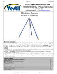
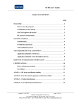
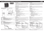
03/10/03 rev. 3/5/2014 WP, manual.doc WP AND SP SERIES FORK-MOUNTABLE WORK PLATFORMS USE & MAINTENANCE MANUAL KEEP THIS MANUAL FOR FUTURE REFERENCE OF OPERATORS. CHECK VESTIL.COM FOR UPDATES TO THE MANUAL. DO NOT USE UNLESS EACH LABEL IS AFFIXED TO THE PLATFORM (AS SHOWN IN FIG. 12 ON P. 14), UNDAMAGED AND READABLE. WP-3737-FD CAPACITY: 600LB (273KG) WP-SERIES 1,000LB (455KG) SP-SERIES 1,000LB (455KG) VESTIL MANUFACTURING CORP. 2999 NORTH WAYNE STREET, P.O. BOX 507, ANGOLA, IN 46703 TELEPHONE: (260) 665-7586 -OR- TOLL FREE (800) 348-0868 FAX: (260) 665-1339 URL: WWW.VESTILMFG.COM EMAIL: [email protected] NOTE: Compliance with regulations, codes, and/or statutory (non-voluntary) standards enforced in the location where the platform is used is exclusively the responsibility of the end-user. Table of Contents Table of Figures Product Introduction………………………... 2 – 3 Safety Principles……………………............. 4 Safety Guidelines…………………............... 4 – 5 Inspections…………………………………… 5 Loading the Platform………………………. 8 Use Instructions……………………………. 9 Setup/Fold-Down Instructions (WP-3737-FD)……………………………. 10 - 11 Mounting Casters to WP-Series Platforms.. 12 Emergency Stop Switch Installation………. 13 Limited Warranty……………………………. 15 NOTES………………………………………. 16 Fig. 1 “WP-series Diagram & Parts List”………… ………. 6 Fig. 2 “SP-175 series Diagram & Parts List”………………6 Fig. 3 “Center of Gravity Diagram”………………………… 7 Fig. 4 “Mast Guard Hinge”……………..…………………… 7 Fig. 5A & 5B Tine Lock Operation…….………..…………. 8 Fig. 6 “Proper attachment of nylon safety strap”……........ 8 Fig. 7 “Caster Insertion”…………………………………….. 12 Fig. 8 “FTJB & WPJB mounting diagram”………………… 13 Fig. 9 “Electrical system diagram”…………………………. 13 Fig. 10 “Mounting WPJB”……………………………………13 Fig. 11 “[WPJB] Fastener order”…………………………… 13 Fig. 12 “Product Markings & Labels”……………………… 14 1 of 16 Copyright 2010 Vestil Manufacturing Corp. 03/10/03 rev. 3/5/2014 WP manual, operation instructions.doc PRODUCT INTRODUCTION Thank you for purchasing a fork-mountable work platform (“platform” or “work platform”) made by Vestil Manufacturing Corporation (“Vestil”). Our platforms are durable, high-quality products that combine safety-conscious design features and rigorous engineering. Although use and maintenance procedures are relatively intuitive, all persons who might use or maintain this product must familiarize themselves with the instructions provided in this manual. Standard design features include: fork pockets that receive the tines (forks) of a fork lift; mast guard; guard rails with either 1 or 2 gates; and either a safety chain or safety strap to secure the work platform to the fork carriage to prevent the work platform from sliding off of the forks if the lift operator accidentally tilts the mast forward during use. Dimensions and other product specifications of offered models appear in the following tables: Platform dimensions Width x Length in inches (~cm) WP-3636 36 x 36 (91 x 91)cm WP-3648 36 x 48 (91 x 122)cm WP-4848 48 x 48 (122 x 122)cm WP-4848-FF 48 x 48 (122 x 122)cm WP3636-84B 36 x 36 (91 x 91)cm WP-3648-84B 36 x 48 (91 x 122)cm WP-4848-84B 48 x 48 (122 x 122)cm WP-4848-FF-84B 48 x 48 (122 x 122)cm WP-3636-DD 36 x 36 (91 x 91)cm WP-3648-DD 36 x 48 (91 x 122)cm WP-4848-DD 48 x 48 (122 x 122)cm WP-4848-DD-FF 48 x 48 (122 x 122)cm WP3636-84B-DD 36 x 36 (91 x 91)cm WP-3648-84B-DD 36 x 48 (91 x 122)cm WP-4848-84B-DD 48 x 48 (122 x 122)cm WP-4848-FF-84B-DD 48 x 48 (122 x 122)cm *WP-3737-FD 37 x 37 (94 x 94)cm Model (FOLD-DOWN MODEL) Distance between the centers of fork pockets in Inches (~cm) 16 (41cm) 16 (41cm) 24 (61cm) 24 (61cm) 16 (41cm) 16 (41cm) 24 (61cm) 24 (61cm) 16 (41cm) 16 (41cm) 24 (61cm) 24 (61cm) 16 (41cm) 16 (41cm) 24 (61cm) 24 (61cm) 26 (66cm) Height of (expanded metal) mast guard 60 60 60 60 84 84 84 84 60 60 60 60 84 84 84 84 60 (152cm) (152cm) (152cm) (152cm) (213cm) (213cm) (213cm) (213cm) (152cm) (152cm) (152cm) (152cm) (213cm) (213cm) (213cm) (213cm) (152cm) Net weight in pounds (~kg) 200 230 275 295 246 259 300 316 234 247 288 304 246 259 300 316 175 (91kg) (105kg) (125kg) (134kg) (112kg) (118kg) (136kg) (144kg) (106kg) (112kg) (131kg) (138kg) (112kg) (118kg) (136kg) (144kg) (80kg) “Stock-picker” (SP) series work platforms SP-175 SP-175-84B 30 x 20 (76 x 51)cm 30 x 20 (76 x 51)cm 24 (61cm) 24 (61cm) 60 (152cm) 84 (213cm) 185 (84kg) 190 (86kg) NOTE: To calculate the weight of a “fully loaded platform,” select the specific model you own/use, find the net weight of your model in the table above, and then add: 1) 1,000 pounds (455kg) for all WP-series models except the fold-down WD-3737-FD; 2) 1,000 pounds (455kg) for SP model platforms; or 3) 600 pounds (273kg) for WP-3737-FD platforms. Work platform safety options Item designation WP-CA WP-SB WP-SB-FTJB WP-SB-WPJB WP-TC WP-P-TC WP-TT36 WP-TT48 WP-AFR WP-WS WP-DL Description 4in. x 2in. mold-on rubber casters Emergency stop button kit Emergency stop junction box – Fork truck Emergency stop junction box – Work platform Fluorescent tube caddy Fluorescent tube caddy (plastic) 36in. tool tray 48in. tool tray Automatically deploying ramp Caution sign with necessary mounting hardware Double chain door lock 2 of 16 Copyright 2010 Vestil Manufacturing Corp. Weight in pounds (~kg) 24 (~11kg) 9 (~4kg) 4 (~1.8kg) 5 (~2kg) 12 (~5.5kg) 6 10 276 2 2 (~2.4kg) (~4.5kg) (~125kg) (~0.9kg) (~0.9kg) 03/10/03 rev. 3/5/2014 WP manual, operation instructions.doc Recommended Lanyard and Safety Harness Options (see sizing chart below) Item designation WP-LH-S WP-LH-M WP-LH-L WP-LH-XL WP-LH-XXL WP-LH-XXXL Description Small harness Medium harness Large harness Extra large harness Extra-extra large harness Extra-extra-extra large harness Height 5ft 4in – 5ft 7in (163 – 170)cm 5ft 8in – 5ft 11in (173 – 180)cm 6ft – 6ft 3in (183 – 191)cm 6ft 3in and Taller 191cm and taller Lanyard length in feet (~m) 6 (~1.83m) 6 (~1.83m) 6 (~1.83m) 6 (~1.83m) 6 (~1.83m) 6 (~1.83m) Weight in pounds (~kg) 10 (~4.5kg) 10 (~4.5kg) 10 (~4.5kg) 10 (~4.5kg) 10 (~4.5kg) 10 (~4.5kg) Waist size 42"-44" 46"-48" 50"-54" 56"-60" Small Medium Large X-Large XX-Large Small Medium Large X-Large XX-Large XXX-Large Medium Medium Large X-Large XX-Large XXX-Large Large Large X-Large X-Large XX-Large XXX-Large 34"-36" 38"-40" Small Platform Model WP-series except fold-down SP-series Fold-down WP-3737-FD Maximum Rated Load 1,000 1,000 600 Vestil Manufacturing Corp. created this manual to acquaint owners and operators of our fork-mounted work platforms with safe operation and maintenance procedures. Employers are responsible for instructing employees to use the product properly (see OSHA standard 1910.178 and 1993 letter of interpretation accessible at http://www.osha.gov/pls/oshaweb/owadisp.show_document?p_table=INTERPRETATIONS&p_id=21322). Employees and any other persons who might assemble, use, or perform maintenance on the platform must read and understand every instruction BEFOREHAND. Users should have access to the manual at all times and should review the directions before each use. Contact Vestil for answers to any question that remain after reading the entire manual. Although Vestil diligently strives to identify foreseeable, hazardous situations, this manual cannot address every conceivable danger. The end-user is ultimately responsible for exercising sound judgment at all times. 3 of 16 Copyright 2010 Vestil Manufacturing Corp. 03/10/03 rev. 3/5/2014 WP manual, operation instructions.doc SAFETY PRINCIPLES Vestil manufactures several distinct models of work platform: WP-series, SP-series, and the completely collapsible WP-3737-FD. The variants offer different platform dimensions, the number of gates, height of mast guard, and maximum rated load. Each unit conforms to the generalized specifications disclosed in this manual and fulfills our demanding standards for quality, safety and durability. Vestil Manufacturing Corp. recognizes the critical importance of workplace safety. Each person who might participate in the use or maintenance of the product must read this manual and fully understand the directions BEFORE using or performing maintenance on the platform. If you do not understand an instruction, contact Vestil for clarification. Failure to adhere to the directions in this manual might lead to serious personal injury or even death. Vestil is not liable for any injury or property damage that occurs as a consequence of failing to apply either: 1) the instructions that appear in this manual; or 2) the information provided on labels affixed to the product. Furthermore, failure to exercise good judgment and common sense may result in property damage, serious personal injury or death. Such failure is solely the fault of the person(s) who acted without good judgment; it is not another responsibility of Vestil. This manual uses SIGNAL WORDS to classify personal injury risks or situations that might lead to property damage, as well as to draw attention to safety message(s). The reader must understand that each signal word indicates the seriousness of the described hazard. Identifies a hazardous situation which, if not avoided, WILL result in DEATH or SERIOUS INJURY. Use of this signal word is limited to the most extreme situations. Identifies a hazardous situation which, if not avoided, COULD result in DEATH or SERIOUS INJURY. Indicates a hazardous situation which, if not avoided, COULD result in MINOR or MODERATE injury. Identifies practices likely to result in product/property damage, such as operation that might damage the platform. SAFETY GUIDELINES Failure to read and understand the instructions included in this manual before using or servicing the work platform constitutes misuse of the product. Study the entire manual before you use the product for the first time and before each subsequent use. Read the manual to refresh your understanding of the safe use, inspection and maintenance procedures explained on p. 5. If questions remain about the product after you finish reading the manual, contact Vestil for answers. DO NOT attempt to resolve any problems with the work platform unless you are authorized to do so and are certain that it will be safe to use afterwards. Electrocution might result if the work platform contacts electrified wires. Reduce the likelihood that platform occupants or bystanders might be electrocuted by applying common sense: DO NOT contact electrified wires with any part of the platform; DO NOT use the platform in an area where contact with electrified wires is likely; DO NOT use the work platform in close proximity to electrified wires or other sources of electricity. Material handling is dangerous. Improper or careless operation might result in serious personal injuries sustained by the boom operator(s) and bystanders. Your use of the platform must always conform to OSHA “Powered industrial trucks” regulations (29 CFR 1910.178 accessible at http://ecfr.gpoaccess.gov/cgi/t/text/textidx?c=ecfr&sid=96a878227f273aa6ec3cea186e1c142b&rgn=div8&view=text&node=29:5.1.1.1.8.14.37.3&idno=29 ). In addition to requirements by law, work platform users should conform to the following: Contact the manufacturer of your lift truck to verify that the truck is capable of safely handling the fully loaded platform (see “NOTE” on p. 2). The width of your platform must be equal to or less than the width of your fork truck plus 10 inches (250mm). DO NOT exceed the maximum occupancy ratings for each model: o WP-series = 2; o SP-175 = 1; o WP-3737-FD = 2. ONLY use the work platform as a means for lifting people and necessary tools and equipment. DO NOT use a structurally compromised work platform. Examples of structural damage includes: broken railings, broken fork pockets, and holes produced by rust or corrosion in the platform floor or mast guard. Inspect the platform before each use according to the inspection instructions on p. 5. DO NOT use the platform unless it passes every part of the inspection. DO NOT use a damaged platform. Inspect the unit before each use according to the inspection instructions on p. 5. DO NOT use the platform unless it passes every element of the inspection. Platform occupants and fork truck operators must wear hard hats whenever this platform is used. 4 of 16 Copyright 2010 Vestil Manufacturing Corp. 03/10/03 rev. 3/5/2014 WP manual, operation instructions.doc (Continued from p. 4) DO NOT use the platform if the safety chain/strap is damaged or missing; DO NOT lift the platform until it is securely connected to the carriage of the fork truck with the safety strap. NOTE: The safety chain/strap is the primary safety mechanism, and must be used each time the work platform is used! To use the safety chain/strap properly, attach the device to the fork truck carriage as instructed in Step 2 on p. 9. Each work platform also includes a secondary safety feature called a tine lock that secures the platform to a tine of your fork truck. However, the lock might not fit over the heel of the tine of your fork truck. If this is the case, do not modify the tine lock; simply do not use it. DO NOT attempt to support a load that weighs more than the platform’s maximum rated load. The net weight, i.e. the sum of the weight of all occupants and everything else supported by the platform, cannot exceed the maximum rated load of the platform. DO NOT stand beneath or travel under the platform while it is elevated. DO NOT use the gate(s), chains, mast guard, guardrails, etc. as a step. Platform occupants must ALWAYS use personal fall protection equipment securely attached to the platform at an anchorage point (see “Operation and use” diagrams on p. 9) as long as the platform is elevated. Only disconnect from an anchorage point when the platform rests securely on the ground. DO NOT use UNLESS each label shown in Fig. 12 on p. 14 is affixed to the platform, undamaged and readable. Inspections Before each use inspect the listed components: 1. Tine lock(s): confirm normal function. Model specific tine lock information appears on p. 8. 2. Snap hook attached to the free end of the nylon safety strap: confirm that the spring latch automatically closes securely against the hook as spring shown in the diagram to the right. If the hook, nylon strap, or latch is latch damaged, do not use the platform until a complete, new safety strap is obtained and attached to the platform cold shut (see p. 9). 3. Gate latch(es): hook WP-3737-FD: confirm that each gate latch functions normally (see “Step 4” on p. 11); Nylon safety strap SP-175 series: confirm chains, cold shuts, snap rings and D-rings are undamaged; WP-series: gate(s) are spring-actuated and should automatically close when released. If a gate(s) does not automatically close, replace the spring before resuming use of the platform. 4. Handrails: check the rails, rail welds, and points of attachment to the platform for bending, warping and cracking. 5. Lanyard attachment points: check the anchorage weldment (see diagrams on p. 9) and points of attachment to the mast guard for bending, warping, or cracking. 6. Casters (if equipped with WP-CA kit): check the casters to confirm that each one is properly seated within the corner handrail posts (see p. 12). 7. Product labels: all labels should be readable and located as shown in the diagram on p. 14. If a label(s) is unreadable or missing, contact Vestil to order a replacement. At least 1 time per month, inspect: 1. Fasteners (hardware): Mast guard hinge - bolts, nuts, washers; Tine lock - pins, cotter pins, spring pins, and tine brackets (see p. 8); Gates – chains, latches, hinges, pins, springs. 2. Casters: look for excessive wear, bending or cracking; if present, do not use the casters to move the platform until the damaged caster(s) is replaced. 3. Fork pockets: confirm that each pocket is structurally sound, not corroded or rusted. Do not use the platform if the fork pockets are structurally compromised or excessively rusted or corroded. 4. Welds: confirm that all welds are intact. 5. Obvious damage to, or structural deformation of, handrails, gate(s), or the platform itself. 6. Overall condition of platform: the structure should be clean, square and rigid, and free of rust and corrosion. Remove dirt and debris. Do not use the platform if the base is excessively rusted or corroded. 5 of 16 Copyright 2010 Vestil Manufacturing Corp. 03/10/03 rev. 3/5/2014 WP manual, operation instructions.doc FIG. 1: WP-series Diagram & Parts List 6 1 [Upper mast guard] 7 8 Item No. Description Quantity Upper mast guard weldment WP-3636 models: Standard mast guard 14-514-125 48in. (Cal-OSHA) upper mast guard 14-514-128 Cold shut 9 WP-3648 models: Standard mast guard 48in. (Cal-OSHA) guard 1 5 4 3 4 5 6 7 8 9 10 10 2 1 14-514-125 14-514-128 WP-4848 models: Standard mast guard 14-514-126 48in. (Cal-OSHA) guard 14-514-129 ½” – 13 x 1-1/4” zinc-plated HHCS 11207 bolt ½” – 13 nylock nut 37030 Hinged gate weldment 14-514-093 #11 hitch pin 45286 ½” x 2” hex head bolt 10211 ½” – 13 UNC hex nut 36109 7/16” x 14” round head pin 14-112-009 9/16” x 2-1/4” spring 14-146-002 WP tine lock assembly 14-537-007 Nylon safety strap 08-145-028 Complete tine lock assembly 14-537-007 2 Bracket locking spring pin Part No. 3 2 2 1 1 2 2 1 1 1 1 1 NOTE: Cold shut is used to secure the nylon safety strap to the midrail. Tine bracket FIG. 2: SP-175 series Diagram & Parts List Item no. 1 Part no. 14-112-001 Description 5/8in. x 9-1/2in. pin 2 45286 1/8in. x 2-5/8in. (#11) hitch pin clip 2 3 37-028-014 Fork tubes 2 4 14-514-127 1 6 14-514-130 1/4in. cold shut 10211 Upper mast guard (standard); OR Upper mast guard (Cal-OSHA) Cold shut (clips for entryway chains ½ in. x 2in. hex head bolt 7 36109 ½ in. – 13 UNC hex head nut 2 5 7 6 Quantity 2 4 2 4 Cold shut (secures the nylon safety strap to midrail) 3 2 Nylon strap 1 Close-up of tine lock assembly 6 of 16 Copyright 2010 Vestil Manufacturing Corp. 03/10/03 rev. 3/5/2014 FIG. 3: Center of Gravity Diagram WP manual, operation instructions.doc Horizontal center of gravity (B) measured from back of mast guard Mast guard Lanyard attachment points WP-series center of gravity (C.O.G.) Vertical center of gravity (A) calculated from bottom of platform floor Model WP-3636 WP-3648 WP-4848 WP-4848-FF WP-3636-84B WP-3648-84B WP-4848-84B SP-175 A: Vertical center of gravity in inches (~cm) 17.9 16.8 16.6 16.6 23.5 21.9 22.0 11.4 (45.5cm) (42.7cm) (42.2cm) (42.2cm) (59.7cm) (55.6cm) (55.9cm) (28.9cm) B: Horizontal center of gravity in inches (~cm) 13.6 19.0 18.6 18.6 12.3 17.4 17.0 16.8 (34.5cm) (48.3cm) (47.2cm) (47.2cm) (31.2cm) (44.2cm) (43.2cm) (42.5cm) Model WP-3636-DD WP-3648-DD WP-4848-DD WP-4848-DD-FF WP-3636-84B-DD WP-3648-84B-DD WP-4848-84B-DD WP-3737-FD A: Vertical center of gravity in inches (~cm) 18.1 18.8 16.8 16.8 23.4 21.9 21.9 16.5 (46.0cm) (47.8cm) (42.7cm) (42.7cm) (59.4cm) (55.6cm) (55.6cm) (41.9cm) B: Horizontal center of gravity in inches (~cm) 13.7 17.0 18.5 18.5 12.5 17.3 17.0 18.0 (34.8cm) (43.2cm) (47.0cm) (47.0cm) (31.8cm) (43.9cm) (43.2cm) (45.7cm) Fig. 4: Mast Guard Hinge Upper mast guard Lower mast guard Hex nut Bolt Close-up of connection between top and bottom portions of mast guard. 7 of 16 Copyright 2010 Vestil Manufacturing Corp. If the mast guard is improperly fastened, it cannot adequately protect platform occupants. Therefore, make sure that hinge fasteners (circled in the drawings) are tightened to 35ft·lb of torque. Retighten the connection to 35 ft·lb whenever: 1. The work platform is taken out of storage: Raise the upper portion of the mast guard, and then Tighten the bolts and nuts. 2. If the mast guard is bumped or deflected from vertical. Immediately lower the platform to the ground; then Straighten the mast guard (return it to the vertical orientation) and retighten the bolts and nuts. 03/10/03 rev. 3/5/2014 WP manual, operation instructions.doc Loading the platform Each of our work platforms includes 2 means for securing the platform to a fork lift: 1) tine lock, AND 2) nylon safety strap. Step 1: Attach the platform to a fork truck: Drive the fork truck forward until the mast guard contacts the back of (vertical part) the tines. For all WP models, make sure that the tines extend through the front and rear fork pockets (see diagram below). Attach the platform to the fork truck’s fork carriage with the securing chain, and capture the heel of the fork with the tine lock underneath the corner of the platform as shown in the drawings below. NOTE: The safety chain/strap is the primary safety mechanism, and must be used each time the work platform is used! To use the safety chain/strap properly, attach the device to the fork truck carriage as instructed in Step 2 on p. 9. Each work platform also includes a secondary safety feature called a tine lock that secures the platform to a tine of your fork truck. However, the lock might not fit over the heel of the tine of your fork truck. If this is the case, do not modify the tine lock; simply do not use it. 8 of 16 Copyright 2010 Vestil Manufacturing Corp. 03/10/03 rev. 3/5/2014 WP manual, operation instructions.doc Step 2: Fasten the nylon safety strap to the fork carriage. The nylon strap is an essential safetyenhancing feature. If the forks are accidentally tilted towards the ground, the strap will not prevent the platform from sliding off of the fork lift if it is improperly connected to either the platform or the fork lift. Use the strap to connect the work platform to the carriage of your fork truck. Wrap the strap around the carriage with no slack at one of the points indicated by dotted arrows in Fig. 6 (vertical midpoint of carriage). FIG. 6: Proper attachment of nylon safety strap Mast As delivered to you (end-user) the strap is connected to the mid-rail. Each time the platform is engaged by a fork lift, the Carriage other end of the nylon strap must be connected to the fork Fork carriage. (tine) WP-3737-FD platforms For all other WP-series platforms, the maximum rated load is 1,000 pounds (455kg). The load rating is posted on the “Warning” placard fastened to the mast guard. Only use the platform to lift one or two people along with necessary light Proper loading (SP-series) tools and equipment. Maximum occupancy is two persons. The maximum rated load of SP-series platforms is 1,000 pounds (455kg). These platforms are designed to lift only one person as well as a skid supported by the fork tubes. This arrangement allows the platform occupant to either remove stock from, or place stock onto, shelves. The weight of the skid loaded supported by the fork tubes must not produce a horizontal load center more than 20 inches (~51cm) from the front of the stock platform (see diagram below). Combined weight of skid and load must not produce load center more than 20 inches from front of work platform. (Front of platform indicated by solid line; 20in. in front of platform indicated with dashed line.) Fork tubes (see arrows): use to support & lift only 1 skid at a time. Use instructions The platform user, fork truck operator, and/or bystanders might sustain serious personal injuries or could be killed if the WP or SP is misused. Occupant(s) or fork truck operators, who disregard obvious hazards, commit product misuse and bear sole responsibility for the consequences. To reduce the likelihood of harmful consequences: Both the WP-series and SP-series products are medium-duty rated platforms. ONLY use with sit-down rider, high lift fork trucks having a minimum load capacity of 3,000 pounds at a 24” load center. ALWAYS review the “Warnings and Safety Instructions” on p.1 before each use. ALWAYS apply the operation recommendations of Occupational Safety and Health Administration (OSHA) standard 1910.178 “Powered industrial trucks”. (See 29 CFR 1910.178 at http://ecfr.gpoaccess.gov/cgi/t/text/textidx?c=ecfr&sid=41e086cb8bf5a6958eb8533944227b80&rgn=div8&view=text&node=29:5.1.1.1.8.14.37.3&idno=29). Apply ANSI/ITSDF B56.1-2005, “Safety Standard for Low Lift and High Lift Trucks,” suggestions regarding the use of fork-mounted work platforms. The publication is freely downloadable: http://www.itsdf.org/pB56.asp When raised 4 feet (~1.2m) or higher, any person who occupies the platform Safety must wear a safety harness and lanyard. placard SP models: The platform occupant MUST attach a lanyard to an anchoring point. Anchoraing [WP models] Maximum occupancy is 2 weldment persons; only 1 person per anchoring point. Anchoring points [Anchoring points are present at each end of the anchoring weldment and these features are identified in the drawings to the right.] Do not lean against the handrails or safety chains. Anchoring points [Rear view] Only use the work platform on smooth, level, finished surfaces capable of supporting the combined weight of the person(s) occupying the platform and all equipment and/or material present on the platform, the platform, and the fork lift. 9 of 16 Copyright 2010 Vestil Manufacturing Corp. 03/10/03 rev. 3/5/2014 WP manual, operation instructions.doc (Continued from p. 9) Avoid sudden stops or quick turns while transporting the platform. DO NOT drive the fork truck while the platform is occupied. If it is necessary to reposition the fork truck or to relocate the platform, fully lower the forks, require all persons to disconnect safety lanyards and dismount the platform. Set the parking brake before lifting the platform. Hold onto the handrail on two sides of the work platform whenever rising or lowering. If the platform is equipped with (optional) casters, DO NOT move the platform if it is occupied. Require all persons to get off of the platform AND unload the platform completely BEFORE repositioning or relocating it. Before entering the work platform, secure the platform to the (fork truck) mast. Inspect all of the platform structure for signs of damage, and verify that the gate latch and / or chain(s) will secure properly. Model WP: push open the gate to enter the work platform; then release the gate. The gate automatically returns to the closed position. Push outwardly on the gate to confirm that it is locked. Models having a gate on both sides (WP-####-DD): after entering this work platform from either side, let go of the gate to allow it to close automatically. Confirm that both gates function properly, i.e. fully and automatically close, before proceeding to use the platform. Model SP-175: enter the platform and then latch both of the safety chains to the D-rings. When using the platform to load stock, the forklift driver should orient the platform parallel to the shelving/racking. Model WP-3737-FD: enter the platform from either side, and then pull the gate closed. Lift the gate, pull the gate fully closed, and then press the gate downward to secure the latch (see “Setup/fold-down instructions”). Confirm that both gates are latched. Setup / fold-down instructions [Model WP-3737-FD]: Folding the platform creates pinch points. Failure to avoid pinch points could lead to injury. Avoid the (obvious) injury hazards created as parts of the platform fold: keep feet, hands and clothing away from pinch points while folding or setting up the work platform. Step 1: Identify the mast guard latching pegs and the fabricated slots as shown below. Step 2: Raise the mast guard. PEG SLOT Nylon safety strap Once the guard is nearly vertical, lift it to allow the pegs to fit into the slots as the guard drops into position. 10 of 16 Copyright 2010 Vestil Manufacturing Corp. 03/10/03 rev. 3/5/2014 Step 3: Raise the front guard rail. Pivot the rail assembly toward the front of the platform. WP manual, operation instructions.doc Step 4: Close and latch the gates. Secure the assembly in place with the pegs and slots. Lift the gate to allow the peg welded to the free end can fit into the corresponding locking slot welded onto the mast guard. Step 5: Secure the platform to the tines of the fork lift. The nylon strap is an essential safetyenhancing feature designed to connect the work platform to the carriage of a fork lift. Improperly connecting the nylon safety strap to either the platform or the fork lift might eliminate the safety benefit. a.) Drive the fork lift tines into the fork pockets on the underside of the platform; then secure the platform to the fork lift with the tine lock (see Step 1 and FIG. 5A & 5B on p. 9). b.) As delivered to you--the end-user--the strap is connected to the base of the mast guard (see “Safety strap connection diagram” on p. 9). To order replacement parts: Vestil uses only quality parts to make the equipment we manufacture. Vestil bears no responsibility for problems that result as a consequence of using unapproved replacement parts. To order replacement or spare parts for this equipment, contact the factory. 11 of 16 Copyright 2010 Vestil Manufacturing Corp. 03/10/03 rev. 3/5/2014 WP manual, operation instructions.doc Instructions for mounting casters to platform models WP-3636, -3648, & -4848 Improperly installed, utilized, or maintained casters could make the platform unsafe to use. To reduce the likelihood of serious injury: READ EACH INSTRUCTION BEFORE BEGINNING THE INSTALLATION. Inspect the casters regularly for damage and to verify that the caster stem is still inserted fully and that it is securely held inside the post. Only use the casters on flat, even, solid surfaces. DO NOT move the platform when loaded with equipment or personnel. Only move the platform by means of the casters if completely unloaded AND unoccupied. Forklift operator: DO NOT lower the platform onto the casters at a rate greater than one foot per second. Gently lower the platform onto the casters to avoid damaging them. 1. Verify that the bottoms of all four of the handrail posts are undamaged and free of foreign material (inside the posts). 2. Raise the work platform high enough to allow the casters to be inserted into the bottom of each of the four posts. 3. Examine each caster; verify that each has a plastic spacer, a black rubber expansion sleeve, and a knurled nut as shown in Figure A. 4. Hold onto the 2½” tightening hub at the top of the caster rig with your hand and snug the knurled nut against the top rubber expansion sleeve. 5. Insert the caster stem into the bottom of the post until the tightening hub is up against the bottom of the handrail post. 6. Turn the tightening hub counterclockwise. If the hub doesn’t tighten, apply side pressure to the caster while turning the hub. Note: The tightening hub must maintain contact with the bottom of the corner handrail post during tightening. FIG. 7: Caster insertion 7. After hand-tightening the hub, pull down on the caster rig to verify that the caster is secured in the post. Corner handrail post Work platform with casters installed Caster stem Knurled nut Expansion rubber Plastic spacer Handrail post Tightening hub Caster rig 12 of 16 Copyright 2010 Vestil Manufacturing Corp. Insert caster into corner post; bottom of post should rest on tightening hub 03/10/03 rev. 3/5/2014 WP manual, operation instructions.doc Emergency stop switch installation The instructions apply ONLY to gasoline-powered fork trucks. If the truck designated for use with work platforms is powered either by battery or diesel fuel, contact the truck manufacturer for installation directions. Item No. 1 2 3 4 5 Description Quantity ¼ in. - 20 x 1in. ¼ in. - 20 lock nut ¼ in. flat washer ¼ in. fender washer Fork truck junction box (FTJB) 8 8 8 4 1 FIG. 8: FTJB and WPJB mounting diagram Coil cord 5 6 Mast guard Mounting plate with bolt holes Jumper cord 6 Work platform junction box (WPJB) Jumper plug 1 E-stop button #6 Work platform junction box (WPJB) E-stop button Mounting plate with bolt holes Coil cord #5 Fork truck junction box (FTJB) Connect to positive side of ignition coil Fork truck battery Pigtail cord Jumper cord FIG. 9: Electrical system diagram Connect to key switch Ignition coil terminal & key switch of lift truck. Disconnect from battery and connect to FTJB 1) Mount the fork truck junction box (5) in an appropriate place on the designated fork lift (for FIG. 10: Mounting WPJB FIG. 11: Fastener order instance, on the operator roll cage/ overhead guard as shown in FIG. 8 & 9 above). Fasten junction box (5) to the lift truck with 4 bolts, 4 flat washers, and 4 Mount WPJB WPJB mounting lock nuts. here plate 4 2) Disconnect the wire leading from the ignition coil 3 (key switch) of the lift truck. Attach the wire to 1 of the 2 1 receptacle terminals inside the fork truck junction box (5). 3) Connect the appropriate wire from the (ignition) key switch to the other receptacle terminal inside the Mast Guard junction box (5). 4) Mount the work platform junction box (6) to the mast guard. Position the junction box as shown in Inner surface (of Outside Fig. 10. Fasten the WPJB to the inside surface of the mast guard) surface mast guard. Proper fastener order is shown in Fig. 11. Use Instructions a) To operate the fork truck without platform attached: plug the FTJB jumper cord into the socket in the FTJB (connect the fork truck junction box to itself). b) Work platform attached: unplug the jumper cord from the FTJB socket; then plug the male plug of the coil cord into the socket of the FTJB. Pull the E-stop button out. 13 of 16 Copyright 2010 Vestil Manufacturing Corp. 03/10/03 rev. 3/5/2014 WP manual, operation instructions.doc FIG. 12: Product Markings and Labels A&B D&E D&E C WP-series platforms C SP-series platforms WP-3737-FD B (Label #082) A (Label #080) D (Label #287) C (Label #525) E (Label #253) 14 of 16 Copyright 2010 Vestil Manufacturing Corp. 03/10/03 rev. 3/5/2014 WP manual, operation instructions.doc LIMITED WARRANTY Vestil Manufacturing Corporation (“Vestil”) warrants this product to be free of defects in material and workmanship during the warranty period. Our warranty obligation is to provide a replacement for a defective original part if the part is covered by the warranty, after we receive a proper request from the warrantee (you) for warranty service. Who may request service? Only a warrantee may request service. You are a warrantee if you purchased the product from Vestil or from an authorized distributor AND Vestil has been fully paid. What is an “original part”? An original part is a part used to make the product as shipped to the warrantee. What is a “proper request”? A request for warranty service is proper if Vestil receives: 1) a photocopy of the Customer Invoice that displays the shipping date; AND 2) a written request for warranty service including your name and phone number. Send requests by any of the following methods: Mail Vestil Manufacturing Corporation 2999 North Wayne Street, PO Box 507 Angola, IN 46703 Fax (260) 665-1339 Phone (260) 665-7586 Email [email protected] In the written request, list the parts believed to be defective and include the address where replacements should be delivered. What is covered under the warranty? After Vestil receives your request for warranty service, an authorized representative will contact you to determine whether your claim is covered by the warranty. Before providing warranty service, Vestil may require you to send the entire product, or just the defective part or parts, to its facility in Angola, IN. The warranty covers defects in the following original dynamic components: motors, hydraulic pumps, electronic controllers, switches and cylinders. It also covers defects in original parts that wear under normal usage conditions (“wearing parts”), such as bearings, hoses, wheels, seals, brushes, and batteries. How long is the warranty period? The warranty period for original components is 90 days. The warranty period begins on the date when Vestil ships the product to the warrantee. If the product was purchased from an authorized distributor, the period begins when the distributor ships the product. Vestil may extend the warranty period for products shipped from authorized distributors by up to 30 days to account for shipping time. If a defective part is covered by the warranty, what will Vestil do to correct the problem? Vestil will provide an appropriate replacement for any covered part. An authorized representative of Vestil will contact you to discuss your claim. What is not covered by the warranty? 1. Labor; 2. Freight; 3. Occurrence of any of the following, which automatically voids the warranty: Product misuse; Negligent operation or repair; Corrosion or use in corrosive conditions; Inadequate or improper maintenance; Damage sustained during shipping; Accidents involving the product; Unauthorized modifications: DO NOT modify the product IN ANY WAY without first receiving written authorization from Vestil. Modification(s) might make the product unsafe to use or might cause excessive and/or abnormal wear. Do any other warranties apply to the product? Vestil Manufacturing Corp. makes no other express warranties. All implied warranties are disclaimed to the extent allowed by law. Any implied warranty not disclaimed is limited in scope to the terms of this Limited Warranty. 15 of 16 Copyright 2010 Vestil Manufacturing Corp. 03/10/03 rev. 3/5/2014 NOTES: 16 of 16 Copyright 2010 Vestil Manufacturing Corp. WP manual, operation instructions.doc