1
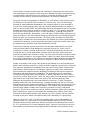
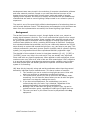
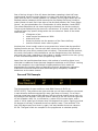
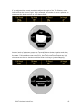
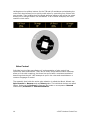
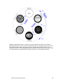
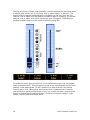
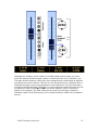
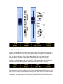
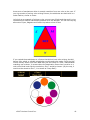
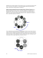
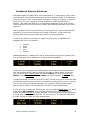
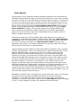
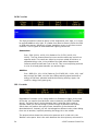
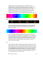
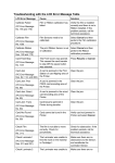
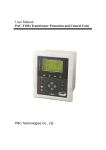
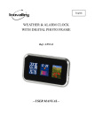
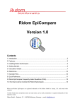
WHITE PAPER UNIVERSAL ATTRIBUTE CONTROL∗ Contents EXPLANATION 1 BACKGROUND 3 PAN AND TILT EXAMPLE 4 ZOOM EXAMPLE 9 SHUTTER CONTROL EXAMPLE 11 GOBO CONTROL 14 ATTRIBUTE SUBSTITUTIONS 18 CONDITIONAL ABSTRACT ATTRIBUTES 21 PHANTOM ABSTRACT ATTRIBUTES 22 COLOR SPACES 23 CONCLUSION 26 ∗ Originally published in February 2005 by Horizon Control Inc. as The Abstract Control Model Universal Attribute Control by Horizon Control Inc. "Simplicity, clarity, singleness: These are the attributes that give our lives power and vividness and joy as they are also the marks of great art." - Richard Holloway Communication and the expression of ideas is central to the art of lighting. Creating great lighting is a team effort lead by the designer. The language a designer uses to communicate with the team, and specifically the console programmer, is crucial to the process of creating the art. The programmer, in turn, must then train the console in order to orchestrate the lights to ultimately relay the intent of the designer to the audience. There is ample opportunity in this process for misinterpretations to muddy the waters of communication. More recently, and at a furious pace, moving lights have entered the theatre and the multitude of options they provide has only complicated this process amplifying the opportunity for 'miscue' of intent. Not surprisingly, there has been an increasing necessity to simplify the process of moving light control. Unlike the hard and fast rules that have existed for decades, a uniform language for designers and programmers to use for describing moving light behaviours has been non-existent. Moreover, the method used to communicate to lights has never been standardized. The pioneering manufacturers of automated lighting equipment each implemented different philosophies of control. More recently, generic moving light console manufacturers have had issues with just covering the bases. It has been a challenge for some to turn the lights on and make them move about. In all respects, these consoles were merely outputting numbers, sometimes masqueraded by words to get the job done. Now that automated lighting is no longer in its infancy, it is time for a fresh new approach on intelligent lighting control. Horizon Control has risen to that challenge and this document will explain how we have achieved that goal with a new philosophy called Universal Attribute Control. Explanation Universal Attribute Control or UAC relies on the idea that the protocol used to control lighting fixtures should be irrelevant to the user. The lighting designer or programmer should have units displayed on their monitor that relate to real life rather than the bit-wise logic that is crammed down the control wire. Using real-world coordinates allows designers to once again think of their lighting fixtures as merely tools available to get the job done. As the theatre embraced intelligent lighting fixtures, it reluctantly accepted all of the idiosyncratic methods needed to control them. The designers found themselves constantly adapting to the language imposed on them by the manufacturer. Gone were the days of simply asking for lights and photons would land on the stage. Lets go back to the advent of computer-controlled lighting to examine the issues that plagued communication in the theatre. Before computers entered the theatre, the most popular dimmer controllers were known as road-boards. These large devices had individual handles for each dimmer and designers would ask operators to move a handle to a position to set the light level. These 'move' instructions were Horizon Control Inc 2007 Page 1 written down as cues and with each one executed in succession you had a show. The advantage of this system (which was only realized fully after the obsolescence of road-boards) was that each move could be controlled at different rates and multiple moves could be executed simultaneously by different operators. Computer control first appeared on Broadway in 1975 when Tharon Musser used the Electronics Diversified LS-8 console on A Chorus Line. This new technology allowed for unprecedented repeatability and a huge number of cues executed in record time. As processing power was very limited, decisions had to be made on how to execute these fades. The technology and code development tools of the day dictated that each channel would be recorded in each cue. This greatly simplified the process of playing back a show, or more specifically, jumping from scene to scene during rehearsals. Remember, in the old days of road-boards, getting to any place at random in the show almost always meant starting from the beginning and executing each cue to ensure accuracy. LS-8 and others could do this with ease. Kliegl quickly followed with the Performance and Strand with Multi-Q and Broadway converted to computer control seemingly overnight. People were blown away with the apparent new flexibility that these computers offered. These early computer control systems did not emulate road-boards, but rather manual preset boards. What designers eventually figured out, given a bit of experience on these consoles, was that they could not achieve the complex cue timing that two or three road-board operators did in the past. As these preset consoles recorded every channel in every cue, they only moved from state to state. This resulted in robotic or non-organic fades. It was only when Strand introduced the original Light Palette in the 1980’s was the technological problem that plagued these fundamental concepts realized on a computer (in North America at least). People everywhere (and since) have praised Light Palette for marrying designer's desires and computer control by using a common language. Almost every controller that has been accepted on Broadway since has used core concepts introduced by Light Palette. With the advent of intelligent lighting, so many more parameters have entered the equation that the language conventions that have evolved are discordant and technologically inadequate. The language must be overhauled. Conventional lighting control just worked in 2-space; Intensity and Time. That is not so with moving light control. There are many many more parameters. Moving light control has long suffered from the lack of this common language that designers and programmers and manufacturers could use. To date, intelligent lighting control has only stumbled along, managing to keep up with an evolving technology and never experienced the sort of watershed event that occurred in the industry with the introduction of Light Palette. The problem was compounded by that fact that industry leaders were extremely protective of their intellectual property. There was no sharing of control protocols between lights and controllers. Each manufacturer vigorously protected the methods they used to control their fixtures and automated systems were sole-source. Only recently has the industry evolved to the point where most believe that inter-operability is a good thing. Horizon Control Inc. (HCI) is at the very leading edge of this new paradigm of lighting control. For years now HCI has had members sitting on ESTA's Control Protocols Working Group and were actively involved in the development of ANSI E1.17 or Architecture for Control Networks (ANC). Horizon Control pulls from over two decades of experience writing lighting control software and members of the 2 2007 Horizon Control Inc. development team were pivotal in the evolution of computer visualization software and other network protocols. People on our staff have worked on some of the largest shows ever mounted with virtually every make and model of popular lighting control systems. Our desire to simplify and revolutionize the fundamental methods that are used to control lighting is deep rooted in our collective years of experience. The result is one of the most highly effective developments of a technology that we call Universal Attribute Control. The descriptions and examples in this document are taken from the implementation as used by the Strand Lighting Light Palette. Background The earliest forms of computer control, though digital at their core, output an analog signal between 0 and 10v. This in turn controlled the lights from no output to full intensity. Inside the console, these numbers were generally stored using 8bit, giving 256 steps of resolution. With the advent of moving light systems, the resolution was doubled to 16-bit, providing 65536 steps of resolution. Computers then calculated fades that produced a one-to-one relationship between the 65,000 steps directly to motors that moved the light from, say, pan-stop to pan-stop. This concept persisted for years and, given a specific controller tied to a specific lighting system, pre-programmed shows were reproduced faithfully night after night. The downfall of this method of control is that these numbers ([0-10], [0-255] or [0-65535]) mean very little in the real world. They are actually only significant when used with very specific equipment. When applied to other equipment, these numbers mean very little at all, and in fact are often meaningless. UAC's objective is to provide an intuitive programming experience and a versatile control system that when played back can actually provide the operator information about the system it is controlling. UAC does this by internally using real world coordinates rather than the protocol defined by individual fixture manufacturers. This has a number of benefits: 1. The 'handles' you use to control moving lights are more inline with what you would do to manipulate conventional lighting. 2. The numbers and 'words' you use to build cues will actually mean something. You will have an idea of what you can do with the lights and what is on stage by reading the screen. 3. If you have mixed equipment, the methodology you use to communicate with your entire rig is identical, regardless of the protocols defined by the equipment manufacturers. 4. Building a set of looks with one group of lights in your rig can be copied to another group, regardless of what type of lights they are. 5. The cues you have in your show file can be played back with any equipment. 2007 Horizon Control Inc. 3 One of the key things in Point #2 above that bears repeating is that UAC uses numbers and 'words' to control lighting. You may claim that has been done for years with the use of 'named' palettes. For example, moving lights desks can use labelled position palettes to build cues and the cue displays use these 'words' to make it easier to read. Don't lose sight of the fact that palettes, like "Down Stage Center", are just placeholders for a combination of values between 0 and 65535. The words themselves do not mean anything to the desk (nor do the numbers). They are just displayed on the screen for convenience. In contrast, with UAC, the words do mean very specific things within the cue structure. Some of the words used include: • 15 degrees of pan • rotate counter clockwise at 6 RPM • strobe at 9 hertz • thrust the shutter into the aperture of the fixture half way • reset the fixture's motor control system At show-time, these 'words' need to be converted into 'values' that the specified lighting fixtures can use. The trick with UAC is that this conversion is figured out each and every time GO is pressed (and not before). That means that the protocol, the mode, the model or the manufacturer can be changed at any time. Moreover, each and every light, regardless of who makes it, appears similar to the user, giving a more consistent experience when programming a show. Apart from the benefits described above, this method of controlling lights is not restricted to traditional linear channels mapped to attributes on the fixture. Looking at a few examples in the Light Palette's implementation of this model will demonstrate the intuitive nature of describing fixtures' attributes as opposed to traditional convoluted methods that sometimes group completely unrelated behaviours on the same channel. Pan and Tilt Example The Home position for pan and tilt on most DMX fixtures is 50:50 (or 32767:32767). This positions the light such that you will have maximum movement in each direction before encountering a stop (pan-stop or tilt-stop). For a fixture that has a total pan range of 360 degrees, with the control channel set to half, you are sitting at 180 degrees. Taking the control channel to full will move the light 180 off axis towards a stop. So, to summarize, a value of 50% means Home, and a value of 100% means go to the pan-stop 180 degrees from Home. Figuring out that 90 degrees is half way in between those two values is easy. That would be 75%. And a 45 degree pan from Home is, again, half way between those two values or 62.5%. That gets a little too complex for the programmer to calculate quickly. 4 2007 Horizon Control Inc. To add to the complication, imagine you have another light in the rig that has a total pan range of 540 degrees. Now the numbers you just figured out for the other fixture mean nothing to this one. Worse yet, if you grab both of the fixtures and pan them in tandem, you would get completely differing results: Using the same values (62.5%), the angles of pan are completely different. The beams of light are not even close to parallel. You can see how this can be very frustrating if you have a mixed rig. With UAC, the Pan attribute is represented in real-world units of degrees. Therefore, when you talk to the light, you tell it to pan so many degrees: Apart from having parallel beams of light from multiple fixtures, notice that there is no need for the "=" sign. Forty-five degrees is forty-five degrees. This makes controlling a rig that is made up of different types of fixtures easy to communicate with and easy to understand. 2007 Horizon Control Inc. 5 If you program the show using one type of fixture, then swap it for another, it is important to remember that it is these real-world values (in this case, degrees) that are used when fading cues, not the DMX values. The example below will demonstrate this with two cues. Cue 1 and Cue 2 are programmed with a fixture that is capable of panning 540 degrees (-270 to +270). Cue 1 takes the fixture to its pan-stop at +270 degrees. Cue 2 has it move (in 10 seconds) to a position of pan +90 degrees. If we were to substitute this fixture out for a fixture that only has a total pan capability of 360 degrees and run the cue, a surprising, but predictable thing happens. When Cue 1 is active, the fixture can't reach +270 degrees, so it stops at its pan-stop (+180 degrees). Then Cue 2 is executed, which is a 10 second fade to +90 degrees. For the fist 5 seconds of Cue 2, the fixture doesn't move. But, when the Live display on the screen reads +180 degrees, which is half way through the cue, the fixture will start to move. When Cue 2 is complete, the fixture will be resting at +90 degrees: Since Universal Attribute Control doesn't figure out the needed protocol numbers (think DMX values) until the very last second, it can also alter the way in which the conversion is done at run-time, producing new and exciting methods of transition during the fade from cue to cue. Various attributes, such as position and color lend themselves very nicely to working in different ways. Color Space is described in 6 2007 Horizon Control Inc. detail below, but let's examine how we can move from one place to another on stage given two stored end places. In this example, we are going to once again consider a moving head fixture as opposed to a moving mirror. Moving head lamps achieve movement by physically moving the source and lens train with two motors within a yoke. This Pan/Tilt relationship equates to a polar coordinate system using azimuth and elevation. When you move in this coordinate system, if you pan more than you tilt, as the beam of light hits your stage, it will move in an arc: We have become used to this characteristic movement of moving heads. Very good moving lights that move extremely smoothly are sometimes described as moving in an organic manner or looking like a follow-spot operator is running them. People are quick to forgive the fact that they are always moving in this arc pattern. UAC gives you the option of how the light will move. It doesn't have to move in an arc. When a follow-spot operator moves a light from point A to point B, the light normally travels in a straight line. 2007 Horizon Control Inc. 7 Light Palette offers a Pan/Tilt mode that alters the way fades are calculated when you press GO. If you record a cue using specific Pan and Tilt values and specify the Movement to be Linear, the end points of the cue do not change, but the method the intervening Pan and Tilt values get from Cue 1 to Cue 2 does. It is not a linear transition mapped to a polar system, but rather a transition that forces the Pan/Tilt mechanism to travel the beam of light in a straight line. The result is that moving lights will look even more organic when programmed this way. 8 2007 Horizon Control Inc. Zoom Example The above example shows that you can swap one fixture for another and get predictable results. Far more useful is the fact that the same values are used to control different types of lights in a similar fashion. Looking at the zoom attribute demonstrates this again. It is quite common to have two or more different types of lights in today's lighting rigs. Matching beam sizes is a process of grabbing one type of light, setting its zoom, then selecting the other and tweaking it to match. You cannot grab both and crank the wheel and hope to get matching results. UAC eliminates the need to remember who made what light when you're programming. Everything in the air is considered a tool to get the job done; why should you be expected to address each light in a different language? Here are two lights; one that has a zoom range of 19° to 70°, the other from 10° to 50°. Cue 1 is written to put both at 30°: It is just that simple! Cue 1 stores a value of 30° and both lights achieve it. Your rig looks consistent and symmetrical with no undesirable surprises and no need for manual re-translation. 2007 Horizon Control Inc. 9 If Cue 2 were written such that both lights go to 70°, as you run it, the fixture on the right would have to give up mid-way: It wouldn't stop the cue from running though. The fixture on the left would go all the way to 70°: To be fair, Cue 2 could not have been written using the fixture on the right. This cue must have been recorded using a fixture that can achieve 70°. Even though in this example it was played back using a 50° fixture, it does not change the cue. If you later swapped it back to a 70° fixture, it would go to 70°. It is only when writing or updating cues that you are limited to the physical constraints of the light currently patched. 10 2007 Horizon Control Inc. Shutter Control Example One the most time consuming endeavours when programming moving lights is shutter control. To achieve desirable effects, the shutter mechanisms need a lot of motors, and hence, a lot of control channels. Typically, most shutter assemblies have nine motors. There are four shutters, each using two motors to control its position within the aperture of the fixture and a ninth to rotate the entire assembly clockwise or counterclockwise. Many times these channels are labelled like this: You can imagine that trying to make some light cuts can be a time consuming effort of hunting and pecking for the right channel or more likely, pair of channels. That is why UAC groups related pairs together onto encoders to reduce the search process by half. UAC labels the shutters like this. 2007 Horizon Control Inc. 11 To get to the shutter control, the encoder banks group opposite shutters together. So the first encoder bank deals with the Top and Bottom shutters. Moreover, motors 1a and 1b are grouped together as Top and placed on the first encoder to thrust the shutter into the aperture of the fixture. The next encoder controls an opposing relationship between those two motors, giving you one handle for controlling the angle of that shutter: The following examples show how UAC greatly simplifies the process of getting ideal shutter cuts. In this example, note the value of Top Thrust. It is set to 50% and the A shutter is cutting the beam in half. If you cranked the first encoder all the way to the right, it is unlikely that it will reach 100%. Most moving lights only allow you to put the shutter in part way into the field of light. That exact amount is represented here in percent. 12 2007 Horizon Control Inc. If you adjusted the second encoder to adjust the angle of the Top Shutter, note how it affects the beam of light. In this example, the shutter is about a quarter the way across the beam and cut to a 15 degree angle. Another bank of attributes groups the Top and Bottom shutter together and when set to a level of 48% the result is a thin bar of light passing through the center of the beam. If this attribute was set to 50%, the fixture would not output any light whatsoever as the two shutters would be either touching or just overlapping. 2007 Horizon Control Inc. 13 Holding down the softkey buttons for the T/B and L/R attributes and adjusting the main level wheel allows you to quickly make a box by controlling four motors with one encoder. Then holding down the Angle attribute softkeys and rolling the wheel allows you to change the box into a diamond. In all of these examples, we never used the ninth motor. Gobo Control Individual moving light manufacturers' implementation of gobo control has notoriously been inconsistent. There are so many things these modern machines allow us to do with imagining, but there has never been a consistent method of describing what they do. UAC attempts to pull in the reins and consolidate on a common language of control. The assembly that holds the entire gobo selection is called the Wheel. Wheels can Spin Forward or Reverse and can Select gobos. The individual choices are called Gobos. Gobos can be Indexed in Degrees like hands on a compass or Rotated continuously Clockwise or Counterclockwise. 14 2007 Horizon Control Inc. Different manufacturers use a variety of control handles to achieve all of these possible behaviours. Some use lots of handles which surprisingly makes the control of the gobo wheel easier, and other insist on bunching up behaviours on only a couple of channels. The examples below are generic and are only used to show how it could be done using linear DMX channels and how it is handled using UAC. 2007 Horizon Control Inc. 15 The first of the pair of these linear channels is used to position the wheel and select a specific gobo and do one of two things with it; either Index it or Rotate it. The second channel changes modes based on the position of the first. Here the first channel is set to about 10% and Selects the Glacier gobo for Indexing. The second channel is set to about 10% which indexes the gobo 15 degrees. Light Palette's attribute bubbles show how this would be achieved using UAC. To rotate the glacier gobo continuously in the clockwise direction, the first handle must be placed at 60%. That changes the mode of the second handle and the 10% position is now meaningless. To see a rotation of 4 RPM clockwise, the channel must be set to 42%. (Where that value comes from is undetermined. Truthfully, you would never get a concise answer even if you to visit the factory that built the fixture and asked the firmware engineers!) To achieve the same results in Light Palette, see the attribute bubbles below. 16 2007 Horizon Control Inc. Changing the direction of the rotation on a DMX based system means you must travel the second handle through a bunch of values that are not of interest to you. The gobo would slow down, then stop, then change direction and speed up again as you adjust the control channel. This can be very disconcerting for a designer who is watching the stage. None of those behaviours were asked for, but were necessary to achieve the desired effect. With UAC, you just nudge the second encoder one tick to change the value from CW to CCW. The fourth encoder, which controls the speed, is not changed. The DMX values would jump from the value needed for clockwise rotation at 4 RPM directly to the counterclockwise 4 RPM value (whatever that is). 2007 Horizon Control Inc. 17 Attribute Substitutions Copying and swapping attributes among fixtures that share scalar properties like Position and Zoom is only the tip of the iceberg when using UAC. The real power of UAC can be seen when you start using similar, but not identical attributes and how UAC can work with them. Color is a great example. There are three primary automated color systems in use today; Subtractive Color Systems like CMY, Additive Color Systems like RGB and Fixed Color Systems that use gel (like scrollers) or dichroic glass (like color wheels). UAC can work with any combination of these three and make intelligent substitutions between them if required. One of the most common modes of color control in automated lighting today is CMY color mixing. Various mechanisms are used to place pure colors in the path of white light to subtract different wavelengths out. By introducing varying amounts of interference, a huge variety of colors can be produced. One of the desirable effects 18 2007 Horizon Control Inc. these sorts of mechanisms allow is smooth transition from one color to the next. If your rig consists of various color mixing fixtures, the attributes are dealt with in a scalar fashion, similar to Zoom. Let’s look at an example of mixing a color on one type of light and then ask it to be reproduced on another that doesn’t possess color mix abilities. You can use varying amounts of Cyan, Magenta and Yellow to produce a hue of Red: If you copied those attributes to a fixture that did not have color mixing, but did have a color wheel, a suitable substitution would need to be made. Since the UAC Fixture Library stores a lot more data than just the name of a color, mathematical matching can be done. In a case where the destination fixture has a scroller or a color wheel that looks like the one below, Slot 7 would be chosen. (By the way, it would not be stored as Slot 7, it is stored as "Deep Red"): 2007 Horizon Control Inc. 19 Working in the reverse direction (from wheel to mix) is of course trivial when using UAC. The library has a definition of what wavelengths make Deep Red and can easily use the color mixing system to recreate it. Gobos are also problematic when using stock fixtures. Different fixtures use different numbers and types of gobos. Imagine that part of your rig has a Linear Breakup gobo that you use in Cue 1. Cue 2 then switches to a Medium Wavy Breakup. The cues were written using a fixture that has a gobo wheel with nine gobos (plus open) and the image below shows how Cue 1 positions the wheel to Slot 1, and Cue 2 positions it to Slot 5. If you wanted to copy this effect to a separate part of your rig, you may not be so lucky to find the same type of fixtures available for those cues. If you use another model of fixture, sensible substitutions (and compromises) must be made. UAC can find similar gobos in the destination fixtures and use them when running the cues. In this case, Cue 1 would select Slot 4, and Cue 2 Slot 3. 20 2007 Horizon Control Inc. Conditional Abstract Attributes Automated lights are riddled with control parameters. In earlier days, many fixture manufacturers combined DMX channels to achieve separate effects in an attempt to prevent the fixture from consuming an outrageous number of channels. A common practice is to use one channel as a mode channel to modify the behaviour of another. This makes life difficult for the lighting programmer as he never knows what a handle will do when he uses it without first checking the state of the mode channels. UAC eliminates this level of confusion by not presenting you with controls that are ineffective on one channel because of the state of another. It goes further by labelling each control appropriately as to what it is doing at present. To get to the plethora of controls on today's moving lights, all attributes are assigned into one of five families: • • • • • Position Color Gobo Lens Special Dedicated buttons or softkeys then 'bank' those attributes onto four encoders and their present purpose is displayed in the large attribute bubbles: In this case, a moving light with multiple gobo wheels has been selected and the user has used the Gobo button to bank the encoders to Gobo Wheel 1's controls (g1). Here the Gobo 1 Wheel Mode is dialed to Select, the current Selection is Glacier and the Gobo Mode is set to Index and which has been Indexed to 15°: It reads somewhat like a book from left to right. The key thing here is that the DMX ordering has nothing to do with how the controls are laid out to the user. In fact, as you will see below in the Gobo examples, the number of DMX channels used to achieve all the effects of the attribute do not enter in the equation either. If the user were to nudge the first encoder, the one labelled Wheel Mode, the entire wheel would Spin Forward. If so, showing you the control that allows you to choose the gobo Selection would be pointless. The entire wheel is spinning through the light path, so you will see them all, not one at a time. The controls exposed to the user change to reflect this new altered state: 2007 Horizon Control Inc. 21 The Wheel Mode encoder now shows that the entire gobo wheel is Spinning Forward. The second encoder now allows you to set the speed at which the wheel spins, in Revolutions per Minute. The third encoder shows that the index/gobo rotation wheel is not moving (it is static, but showing which angle it is positioned to is pointless as the planetary gear motion would make it difficult to identify any single angle). If the first encoder is changed back to Select, the second through fourth encoders will return to their previous function: Nudging the third encoder from Index to Rotate Clockwise changes the purpose of the fourth from Index to Speed and the units change from degrees to RPM. Note that the actual gobo (Glacier) does not change. While this looks straight forward and concise to the user, behind the scenes UAC is mapping all of these controls to the appropriate DMX channels, regardless of how convoluted the protocol is. An added benefit of this method of masking and unmasking attributes is that controls like Speed that use RPM is not overwritten when the encoder changes to Index and uses Degrees. When you come back to Speed, the RPM value you left it at will persist. UAC essentially gives you more handles than the fixture manufacturer allotted. Phantom Abstract Attributes As seen above, exposing additional controls that the fixture manufacturer didn't allot for makes controlling some types of lights more convenient. An ideal example of this is RGB LED fixtures. Traditionally, the only controls the user can adjust are Red, Green and Blue. Distinctly absent is an Intensity attribute. The undesirable side effect of this is that if you pull down the Grand Master, the LEDs intensities remain unchanged. To blackout the fixtures, you have to adjust three parameters rather than one. This becomes inconvenient when you just want to lower LED based fixtures' level or take them out in one cue to only restore them in the next. You must look up the RGB values from the preceding cue to restore them. Horizon Control's UAC adds a phantom attribute to RGB lights. This intensity attribute does not appear any different from that of any other fixtures', but it does control the overall brightness of the LED without affecting its Hue. Another benefit of having this attribute used in cues is that if you ever do replace an RGB fixture with another, more traditional type of fixture, the Up/Down dynamics of the light are already in the cues. Color Space is a related but unique extension of this methodology and is discussed further below. 22 2007 Horizon Control Inc. Color Spaces Complimentary Color Spaces are basically different methods used to describe the individual components that make up what the eye perceives as color. None of them are right or wrong. They are individual and each one has its purpose. The selection of one over the other is primarily a matter of choice. Most consoles only allow you to work in the color space native to the fixtures you are controlling. That is, if you have a white-sourced light that has Cyan, Magenta and Yellow dichroics place before it, you would be working in the subtractive CMY space. If you have Red, Green and Blue LED lights, you would be working in the additive RGB space. Some consoles have neat color-pickers that allow you to quickly grab desired colors, but at the end of the day, they will be fading from one triplet of CMY (or RGB) to another when they run cues. When working with color mixing capable lights, UAC allows you to choose and crossfade in six different color spaces. These are CMY, RGB, HSL (Hue Saturation Luminance), HSL' (Hue Saturation Luminance Prime) and, depicted in lower case so as not to confuse it with HSL, hsv (Hue Saturation Value) and hsv' (Hue Saturation Value Prime). The difference between the two Hue based color spaces and what the Prime means is explained below. Lighting designers think of light as having three distinct properties; color, intensity of color, and brightness. (This is not a discussion on shape and movement.) In the additive RGB color space, to change the color, you need to change the ratio between the Red, Green and Blue components. If you wanted to change the intensity of the light, you would have to project the vector of the new RGB value toward the largest valued primary color (red, green or blue). With respect to color, the same could be done with CMY, but to simplify the example, we don't want to get into the effects of a dimmer in the equation. If you want to make a color brighter in RGB color space you need to keep the ratios between the Red, Green and Blue the same but increase them. Changing any of these properties on the fly would take some clever mathematics on behalf of the programmer. Horizon Control's UAC uses functions that manipulate the native color channels for you. This math transforms the data at run-time allowing you to program and fade in any one of the six color spaces mentioned above. Regardless of which of the six methods you use to choose your color, you also have the option of how the actual crossfade will execute. In the following three examples, Cue 1 is Blue and Cue 2 is Green, but in each case, we're going to crossfade in a different color space. Apart from the Color Space attribute changing in Cue 2 in each example, all other color attributes remain the same. 2007 Horizon Control Inc. 23 RGB Crossfade The fixture used here could be either a CMY subtractive color light, or it could be an RGB additive color light. If it fades from Blue to Green in either the CMY or RGB color spaces, effectively a linear transition occurs on all three control channels. This is typical of what traditional lighting console do. Subtractive: Cue 1 CMY (100%, 100%, 0%) fades to Cue 2 CMY (100%, 0%, 100%). The first channel does not move and the other two move from opposite ends. The result can either be a not-so-subtle off-white or a somewhat dingy color in the middle of the fade when Magenta and Yellow are both at half and Cyan is at full. This is not surprising as there is a lot of colored glass between you and the light. Additive: Cue 1 RGB (0%, 0%, 100%) fades to Cue 2 RGB (0%, 100%, 0%). Half way through the fade, we have two LEDs producing equal amounts of energy at half their potential and the third doing nothing. Again, the result is a dingy blue-green-gray. HSL Crossfade Regardless of whether you're using Additive or Subtractive lights, at the end of the day you need to provide three control channels (see RGB Crossfade above). You don't have a choice because that is what the light needs to operate. What you can do though is move through a different color space, which does not produce the typical linear transition of the channels as described above. Instead, you will visit altogether different colors when fading from one to another, hopefully avoiding the dingy bit in the middle. The picture below shows the entire color spectrum as it is laid out in the 'Natural' color space. Hue is the ratio between the three primary colors and is 24 2007 Horizon Control Inc. what we think of as color. Saturation is how intense the color is, or mathematically how far apart each primary is from the others or how far away from gray you are (Gray is when all three are equal in value). Luminance is the overall brightness of the selected color, or mathematically defined as the cumulative total of the three primary colors. Too much brightness results in white. Cue 1 shows where Blue is and Cue 2 shows Green. When you press GO on Cue 2, the CMY color flags (or LEDs) will change in such a way that you visit Cyan along the way. In some circumstances, this will be a more desirable transition than that shown above. HSL' Crossfade The Hue Primed version of the well defined HSL color space just shifts the spectrum such that each end does not include Red. It could be shifted any amount, but Horizon Control shifted it 180 degrees, such that Cyan now appears at each end: In the [Cue 1/Cue 2] example, going from Blue to Green in the HSL' color space now produces a virtual rainbow of colors along the way. This can be a very powerful effect, but the transition will be different for every combination of colors recorded and it will be up to the designer to choose. If Cue 1 was Purple and Cue 2 was Yellow, going through Red might not seem like such a bad idea. To do that you would have to use this color space. If you use the more common HSL, you go through Blue, Cyan and Green to get there. Again, maybe that is desirable. hsv The Hue Saturation Value color space is also known as the 'Deep' color space. HSL works well for emissive fixtures like LEDs, but not so good for fixtures that are hitting your set. As you increase the brightness on you set, you don't want the hue to change. UAC offers the hsv color space to solve this problem where Luminance is substituted by value. As the value attribute increases, hues become more saturated. With hsv, hues never progress through the pastels to white. This is equivalent to you pouring more light on your painted set. As you bathe the set in more blue, it doesn't approach white (unless you're working in TV - then all bets are off). 2007 Horizon Control Inc. 25 The choice of how to get from color A to color B is up to you. The method of attack is to write the two cues first, picking the colors using whatever method you choose. Then try running the cue. If you like the transition, you're all done. If you don't, go to Cue 2, change the color space and Update the Cue and run it again. Even though UAC literally fades in all six color spaces, you only have to change between three of them to see all the effects. Choose one of: • • • CMY or RGB HSL or hsv HSL' or hsv' Conclusion For years, designers' hands were tied when they were controlling automated lighting. The language and control structure used had been imposed upon them by the equipment manufacturers. This was not conducive to an enjoyable experience for anyone involved in the process. Horizon Control's Universal Attribute Control defines a common language that designers and programmers can share and the complex processes of translating this language into DMX or any other control protocol is taken care of for you. This new language has not been defined arbitrarily or in a vacuum. We use colloquial terms that have been used in the theatre for years and present them to the programmer with sense and order. Confusing mode channels that change the purpose of other channels have been eliminated and new and uniquely useful control handles have been added, such as an intensity control for LED based fixtures. UAC allows the designer to look at the lighting rig as a unified tool to aid in the design process. The designer will no longer need to conform to the language of the manufacturers and this allows them to diversify the lighting rig without the worry of adding complexity to the programming process. Every fixture now speaks the same language and increased communication and understanding will only lead to better lighting. 26 2007 Horizon Control Inc.