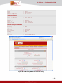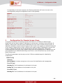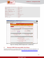
1
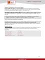
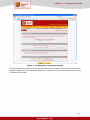
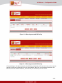
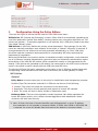
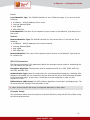
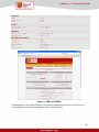
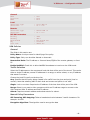
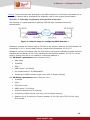
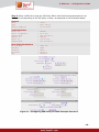
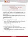
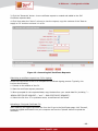
Configuration Guide www.TeamF1.com V-IPSecure User Manual V-IPSecure : Embedded IPsec / IKE Configuration Guide © 2006 TeamF1, Inc. Reproduction in whole or part without written permission is prohibited. V-IPSecure - Configuration Guide V-IPSecure : Embedded IPsec/IKE Configuration Guide for Example Scenarios V-IPSecure is a high-performance, lean and flexible implementation of the IPsec protocol suite which provides IP extensions needed for security services at the network layer. V-IPSecure provides a high-quality cryptography-based secure communication channel on embedded systems. Its end-to-end securing of IP datagrams prevents access or modification of any information from above the IP layer, when passing through intermediate nodes in a public network. This enables secure virtual private networks (VPN) to be carved out of a public and/or insecure network. Designed exclusively for embedded use, V-IPSecure’s robust and configurable implementation makes it an ideal fit for embedded devices such as Internet appliances, VPNs, gateways, secure terminals, routers and other network equipment. Embedded features such as CPU-independence, leveraging platform resources (OS, processor and specialized hardware accelerators) and providing a feature-rich, yet modular implementation to enable trade-offs in constrained environments is a design goal of V-IPSecure. This configuration guide discusses how to setup and configure V-IPSecure for interoperability in common VPN environments. It also includes specific VPN example scenarios recommended by VPNC in Section 4 : Example VPNC Interoperability Test Setup. V-IPSecure can be configured using its APIs, configuration files and when embedded in a managed application, through an external management interface such as a web-based GUI or CLI. In the following examples, a web-based management interface is used to configure V-IPSecure in various scenarios. 1. Configuration Using Wizard Mode The VPN Wizard is a web-based configuration facility that assists with setting up a VPN tunnel from the V-IPSecure enabled target to another gateway or to a VPN client using pre-shared key authentication. Further the generated policies can be used as a starting point for creating more advanced VPN and IKE policies that allow a choice of authentication methods including XAUTH (local user database or RADIUS authentication) and digital certificates. Running the wizard generates the IPsec VPN policy as well as the associated IKE policy VPN with the parameters (both IKE phase 1 and phase 2) chosen based on the VPN Consortium’s (VPNC) recommendations. The values can be viewed by clicking on the VPN Wizard Default Values link at the top of the page. The following parameters can be setup on the V-IPSecure enabled target and corresponding values entered on the other side of the tunnel (the remote gateway or client). Connection Type This VPN tunnel can connect to another peer gateway or to a client. Select "Gateway" to create a tunnel to another VPN gateway. Select "Client IPsec Host" to setup this router for access by remote PCs running VPN client software. Connection Name and Remote IP Type Name: Enter a name for the connection. The name is used for management only. Pre-shared Key: The length of the pre-shared key is between 8 characters and 49 characters and must be entered exactly the same here and on the remote VPN Gateway or Client. -2- V-IPSecure - Configuration Guide Remote IP Address or the Internet Name Remote WAN’s IP Address or Internet Name: Enter the IP address of the Remote peer. Alternatively, you can also specify the Internet name of the peer. The Internet name is defined as the Fully Qualified Domain Name (FQDN) e.g. vpn.TeamF1.com Local WAN IP Address or Internet Name: Enter the IP address or Internet name of the local WAN port. This field can be left blank if you are not using a different FQDN or IP address than the one specified in the WAN port’s configuration. To use a different IP address or FQDN, enter it in this field. # Both local and remote ends should be defined as either IP addresses or Internet Names (FQDN). A combination of IP address and Internet Name is not permissible. Secure Connection Remote Accessibility These parameters are required only for a Remote Gateway connection. Enter the LAN side subnet IP address and the associated subnet mask of the remote gateway. A subnet IP address is one that gives the “network number” of the IP range. For example, a network address of 192.168.1.10 with a subnet mask of 255.255.255.0 would have a network number or subnet IP address of 192.168.1.0. Example Setup: The screenshots below show the setup for the following configuration using the Wizard mode for a gateway-gateway connection with pre-shared keys authentication using the following parameters Peer Connection Name Pre-shared key Remote WAN IP’s Local WAN IP’s Remote LAN IP Remote LAN subnet Mask : : : : : : : Gateway vpn_wiz 12349876 10.1.1.30 10.1.1.10 192.168.2.1 255.255.255.0 -3- V-IPSecure - Configuration Guide Figure 1 : Configuration using wizard mode This automatically generates the VPN and IKE policies shown below. These policies can then be edited to make use of more advanced features in V-IPSecure such as other authentication types or different IKE modes. -4- V-IPSecure - Configuration Guide Figure 2 : Wizard-generated IKE Policy Figure 3 : Wizard-generated VPN Policy Corresponding to the above example, the following parameters will have to be set on the remote gateway using the configuration tools for that gateway. Note the correspondence between the Remote and Local WAN IP address, and that the pre-shared keys are the same. -5- V-IPSecure - Configuration Guide Peer Connection Name Pre-shared key Remote WAN IP’s Local WAN IP’s Remote LAN IP Remote LAN subnet Mask : : : : : : : Gateway vpn_wizard 12349876 10.1.1.10 10.1.1.30 192.168.1.1 255.255.255.0 Configuration Using the Policy Editors 2. There are two types of policies that are used for IPsec VPN tunnel setup: IKE Policies: IKE (Internet Key Exchange) is used in IPsec VPNs for automatically negotiating the core IPsec parameters (called "Auto Mode") including session keys, encryption algorithms etc. IKE policies are optional -- if automatic negotiation is not required, only a VPN policy needs to be setup (also called "Manual" mode). VPN Policies: A VPN Policy defines the primary tunnel parameters. If the settings (for the VPN tunnel are manually entered on each endpoint of the tunnel, a "Manual" VPN policy is required. If some parameters for the VPN tunnel are to be generated automatically, an "Auto" VPN policy should be used and it should be accompanied by its corresponding IKE policy specifying the parameters for negotiation. While the VPN Wizard in the previous section is intended to simplify configuration, more advanced use of V-IPSecure including authentication types other than pre-shared key authentication require direct editing of the VPN and IKE policies (either created from scratch or ones generated by the wizard). If the policies are generated by the wizard, the name used for the VPN Tunnel connection name in the wizard is used to identify both the VPN Policy and IKE Policy. The following IKE and VPN policy parameters can be setup on the V-IPSecure enabled target and corresponding values entered on the other side of the tunnel (the remote gateway or client). IKE Policies General Policy Name: A unique name given to the policy for identification and management purposes. Direction/Type:The connection methods for V-IPSecure can be one of the following: Initiator: The router will initiate the connection to the remote end. Responder: The router will wait passively and respond to remote IKE requests. Both: The router will work in either Initiator or Responder mode. Exchange Mode: There are two negotiation modes supported: Main Mode negotiates the tunnel with higher security, but is slower whereas Aggressive Mode establishes a faster connection but with lower security. # Note: If either the Local or Remote identifier type (defined below) is not an IP address, then negotiation is only possible in Aggressive Mode. If FQDN, User FQDN or DER ASN1 DN is selected, the router will disable Main Mode and set the default to Aggressive Mode. -6- V-IPSecure - Configuration Guide Local Local Identifier Type: The ISAKMP identifier for the V-IPSecure target. It can be one of the following: IP Address – WAN IP address of this router. Internet Address/FQDN User FQDN DER ASN1 DN Local Identifier: The value of the respective option chosen in the Identifier Type drop-list for this router. Remote Remote Identifier Type: The ISAKMP identifier for the remote device. It can be one of the following: IP Address – WAN IP address of the remote machine Internet Address/FQDN User FQDN DER ASN1 DN Remote Identifier: The value of the respective option chosen in the Identifier Type drop-list for remote host. IKE SA Parameters The Security Association (SA) parameters define the strength and the mode for negotiating the SA. The fields in the SA are: Encryption Algorithm: The algorithm used to negotiate the SA. E.g. DES, 3DES, AES-128, AES-192, and AES-256. Authentication Type: Select Pre-shared Key for a simple password based key. Selecting RSASignature will disable the Pre-shared key text box and uses the Active Self Certificate uploaded in the Certificates page. In that case, a certificate must be configured in order for RSASignature to work. Diffie-Hellman (DH) Group: The Diffie-Hellman algorithm is used when exchanging keys. The DH Group sets the strength of the algorithm in bits. # Note: Ensure that the DH Group is configured identically on both sides. Example Setup: The screenshots below show the setup for a sample IKE policy using the IKE Policy Editor using the following parameters: -7- V-IPSecure - Configuration Guide General Name Direction Mode : ike1 : both : main Local Identifier type Identifier : Local WAN IP : 10.1.1.10 Remote Identifier type Identifier : Remote WAN IP : 10.1.1.30 IKE SA Parameters EncrAlg AuthAlg Auth Method Key Life Time : : : : : 3DES SHA-1 Pre-shared key 12345678 28800 sec Figure 4 : IKE Policy Editor Corresponding to the above example, the following parameters will have to be set on the remote gateway using the configuration tools for that gateway. -8- V-IPSecure - Configuration Guide General Name Direction Mode : ike1 : both : main Local Identifier type Identifier : Local WAN IP : 10.1.1.30 Remote Identifier type Identifier : Remote WAN IP : 10.1.1.10 IKE SA Parameters EncrAlg AuthAlg Auth Method Key Life Time : : : : : 3DES SHA-1 Pre-shared key 12345678 28800 sec VPN Policies General The fields in this section are: Policy Name: A unique name for identifying of the policy. Policy Type: Policy can be either Manual or Automatic. Remote End Point: The IP address or Internet Name/FQDN of the remote gateway or client PC. Enable NetBIOS: Check this to allow NetBIOS broadcasts to travel over the VPN tunnel. Traffic Selection Select the IP addresses on the remote and local side that will be part of the tunnel. This can be either a single IP address, several IP addresses in a range, an entire subnet, or any IP address that wants to connect. Choose the Local IP type from the drop list: Any: Specifies that the policy being created is for traffic from the given end point (local or remote). Note that selecting ANY for both local and remote end points is not valid. Single: Limit to one host. Requires the IP address of the host that will be part of the VPN. Range: Select it you want to allow computers within an IP address range to connect to the VPN. Requires Start IP address and End IP address. Subnet: Requires network address and subnet mask of a subnet. Manual Policy Parameters SPI-Incoming, SPI-Outgoing: Takes a hexadecimal value between 3 and 8 characters. For example: 0x1234 Encryption Algorithm: The algorithm used to encrypt the data -9- V-IPSecure - Configuration Guide Integrity Algorithm: Algorithm used to verify the integrity of the data. Encryption Key-In: Encryption key of the inbound policy. The length of the key depends on the algorithm chosen. Encryption Key-Out: Encryption key of the outbound policy. The length of the key depends on the algorithm chosen. Integrity Key-In: This is the integrity key (for ESP with Integrity-mode) for the inbound policy and depends on the algorithm chosen. Integrity Key-Out: This is the integrity key (for ESP with Integrity-mode) for the outbound policy and depends on the algorithm chosen. Auto Policy parameters SA Lifetime: The lifetime of a Security Association can either be specified in seconds or kilobytes. If specified as time, it is the interval after which the Security Association becomes invalid. The SA is renegotiated after this interval. If specified in kilobytes, the SA is renegotiated after the specified number of kilobytes of data is transferred over the SA. It is recommended that the lifebyte specifications be very large numbers or be left blank. Encryption Algorithm: The algorithm used to encrypt the data Integrity Algorithm: Algorithm used to verify the integrity of the data. PFS Key Group: Enable Perfect Forward Secrecy (PFS) to improve security. While this is slower, it will ensure that a Diffie-Hellman exchange is performed for every phase-2 negotiation. Select IKE Policy: Choose the IKE policy that will define the characteristics of phase-1 of the negotiation. Example Setup: The screenshots below show the setup for a sample VPN policy using the VPN Policy Editor using the following parameters for an auto policy corresponding to the IKE policy shown in the earlier example: - 10 - V-IPSecure - Configuration Guide General Name Type Remote Endpoint : vpn1 : auto policy : 10.1.1.30 Traffic Selection Local IP Start IP address Subnet Mask Remote IP Start IP Subnet Mask : : : : : : Subnet 192.168.1.0 255.255.255.0 Subnet 192.168.2.0 255.255.255.0 Auto Policy Parameters SA lifetime EncrAlg AuthAlg DH Group : : : : 3600 sec 3DES SHA-1 group2 Figure 5 : VPN Policy Editor for Auto Policy Corresponding to the above example, the following parameters will have to be set on the remote gateway using the configuration tools for that gateway. - 11 - V-IPSecure - Configuration Guide General Name Type Remote Endpoint : vpn1 : auto policy : 10.1.1.30 Traffic Selection Local IP Start IP address Subnet Mask Remote IP Start IP Subnet Mask : : : : : : Subnet 192.168.1.0 255.255.255.0 Subnet 192.168.2.0 255.255.255.0 Auto Policy Parameters SA lifetime EncrAlg AuthAlg DH Group : : : : 3600 sec 3DES SHA-1 group2 A second example below shows the setup for a sample VPN policy using the VPN Policy Editor using the following parameters for a manual policy: - 12 - V-IPSecure - Configuration Guide General Name Type Remote Endpoint : vpn1 : auto policy : 10.1.1.30 Traffic Selection Local IP Start IP address Subnet Mask Remote IP Start IP Subnet Mask : : : : : : Subnet 192.168.1.0 255.255.255.0 Subnet 192.168.2.0 255.255.255.0 Manual Policy Parameters SPI-Incoming EncrAlg Key-In Key-Out SPI-Outgoing IntAlg Key-In Key-Out : : : : : : : : 0x1234 DES testtest testtest 0x1234 MD5 testtestabcdabcd testtestabcdabcd Figure 6 : VPN Policy Editor for Manual Policy - 13 - V-IPSecure - Configuration Guide Corresponding to the above example, the following parameters will have to be set on the remote gateway using the configuration tools for that gateway. 3. General Name Type Remote Endpoint : vpn1 : manual policy : 10.1.1.10 Traffic Selection Local IP Start IP address Subnet Mask Remote IP Start IP Subnet Mask : : : : : : Subnet 192.168.2.0 255.255.255.0 Subnet 192.168.1.0 255.255.255.0 Manual Policy Parameters SPI-Incoming EncrAlg Key-In Key-Out SPI-Outgoing IntAlg Key-In Key-Out : : : : : : : : 0x1234 DES testtest testtest 0x1234 MD5 testtestabcdabcd testtestabcdabcd Configuration For Remote Access Users To simplify the process of connecting remote VPN clients to a V-IPSecure enabled target, ModeConfig can be used to assign IP addresses to remote users, including a network access IP address, subnet mask, and name server addresses from the router. Remote users are given IP addresses available in secured network space so that remote users appear as seamless extensions of the network. ModeConfig is similar to DHCP and is used to assign IP addresses to remote VPN clients. A ModeConfig record may be selected during IKE policy specification. VPN clients connecting using an IKE policy with a Mode Config record will be assigned an IP address from the pools specified in the selected ModeConfig record. One or more IKE policies may use the same Mode Config record The following parameters can be setup on the V-IPSecure enabled target for ModeConfig configuration. ModeConfig General Record Name: A unique name given to the record for identification and management. First IP Pool Starting IP: The first address to be allocated in this pool. Ending IP: The last address to be allocated in this pool. Second IP Pool Starting IP: The first address to be allocated in this pool. - 14 - V-IPSecure - Configuration Guide Ending IP: The last address to be allocated in this pool. Third IP Pool Starting IP: The first address to be allocated in this pool. Ending IP: The last address to be allocated in this pool. WINS Server Primary: The primary WINS Server IP Address Secondary: The secondary WINS Server IP Address DNS Server Primary: The primary DNS Server IP Address Secondary: The secondary DNS Server IP Address Traffic Tunnel Security Level PFS Key Group: Enable Perfect Forward Secrecy (PFS) to improve security. While this is slower, it will ensure that a Diffie-Hellman exchange is performed for every phase-2 negotiation. Encryption Algorithm: The algorithm used to negotiate the SA. Authentication Algorithm: Specify the authentication algorithm for the VPN header. Diffie-Hellman (DH) Group: The Diffie-Hellman algorithm is used when exchanging keys. The DH Group sets the strength of the algorithm in bits. (This setting must match that of the Remote VPN.) Local IP Address: IP Address of the local LAN subnet. If it is not specified it defaults to LAN subnet corresponding to the LAN IP of the device. Local Subnet Mask: Subnet Mask of the local LAN subnet. Example Setup: The screenshots below show the setup for the following ModeConfig record: - 15 - V-IPSecure - Configuration Guide Record Name First Pool Starting IP Ending IP PFS Key group SA Life time Encr Alg Integrity Alg Local IP Local Subnet Mask : : : : : : : : : : mode_config 10.10.10.1 10.10.10.100 group2 3600 seconds 3DES SHA-1 0.0.0.0 0.0.0.0 Figure 7 : A ModeConfig Record A ModeConfig record may be selected from the IKE policy page to specify the IP addresses to be allocated to the peers matching the policy. When a VPN client matching the policy negotiates a connection, the VPN allocates a “virtual adapter” with IP address, gateway, etc. specified in the ModeConfig record. Example Setup: The screenshots below show the setup for the IKE Policy referring to the ModeConfig record: - 16 - V-IPSecure - Configuration Guide Select Mode Config Record Policy name Mode Local Identifier Type Local Identifier Remote Indentifier Type Remote Indentifier Encr Alg Auth Alg Authentication Method Pre-shared key Group SA Life time : : : : : : : : : : : : : mode_config ike1 aggressive FQDN remote.com FQDN local.com 3DES SHA-1 Preshared key 12345678 group2 28800 Figure 8 : Selecting a ModeConfig Record in an IKE Policy 4. Example VPNC Interoperability Test Setup This section describes how to configure V-IPSecure to implement the scenarios described in the VPN Consortium’s interoperability specification (http://www.vpnc.org/InteropProfiles/Interop- - 17 - V-IPSecure - Configuration Guide 01.html). These scenarios were developed by the VPN Consortium to help users understand how to set up their systems and to understand the vocabulary used in their system documentation. Scenario 1: Gateway-to-gateway with preshared secrets The following is a typical gateway-to-gateway VPN that uses a preshared secret for authentication. Figure 9 : Network setup for configuring VPNC Scenario 1 Gateway A connects the internal LAN 10.5.6.0/24 to the Internet. Gateway A's LAN interface has the address 10.5.6.1, and its WAN (Internet) interface has the address 14.15.16.17. Gateway B connects the internal LAN 172.23.9.0/24 to the Internet. Gateway B's WAN (Internet) interface has the address 22.23.24.25. Gateway B's LAN interface address, 172.23.9.1, can be used for testing IPsec but is not needed for configuring Gateway A. The IKE Phase 1 parameters used in Scenario 1 are: • Main mode • TripleDES • SHA-1 • MODP group 2 (1024 bits) • pre-shared secret of "hr5xb84l6aa9r6" • SA lifetime of 28800 seconds (eight hours) with no kbytes rekeying The IKE Phase 2 parameters used in Scenario 1 are: • TripleDES • SHA-1 • ESP tunnel mode • MODP group 2 (1024 bits) • Perfect forward secrecy for rekeying • SA lifetime of 3600 seconds (one hour) with no kbytes rekeying • Selectors for all IP protocols, all ports, between 10.5.6.0/24 and 172.23.9.0/24, using IPv4 subnets - 18 - V-IPSecure - Configuration Guide To set up Gateway A (assumed to be running V-IPSecure software) for this scenario, use the steps described below. If Gateway B is also running V-IPSecure similar steps may be employed to configure it, with gateway-specific parameters appropriately exchanged: Step 1: Setup an IKE Policy using the IKE Policy Editor using the following parameters as explained in the screenshot below: General Name Direction Mode : conn1 : Both : Main Local Identifier type Identifier : Local WAN IP : 14.15.16.17 Remote Identifier type Identifier : Remote WAN IP : 22.23.24.25 IKE SA Parameters EncrAlg AuthAlg Auth Method Key Life Time : : : : : 3DES SHA-1 Pre-shared key hr5xb84l6aa9r6 28800 sec Figure 10 : Configuring IKE Policy for VPNC Example Scenario 1 - 19 - V-IPSecure - Configuration Guide Step 2: Setup a VPN Policy using the VPN Policy Editor with the following parameters for an auto policy corresponding to the IKE policy in Step 1 as explained in the screenshot below: General Name Type Remote Endpoint : conn1 : Auto Policy : 22.23.24.25 Traffic Selection Local IP Start IP address Subnet Mask Remote IP Start IP Subnet Mask : : : : : : Subnet 10.5.6.0 255.255.255.0 Subnet 176.23.9.0 255.255.255.0 Auto Policy Parameters SA lifetime EncrAlg AuthAlg DH Group PFS : : : : : 3600 sec 3DES SHA-1 Group 2 Enabled Figure 11 : Configuring VPN Policy for VPNC Example Scenario 1 - 20 - V-IPSecure - Configuration Guide This completes the configuration for Scenario 1. At this point, the traffic between Gateway A and Gateway B is encrypted, and can be tested with a utility such as "ping" from Gateway A's LAN to Gateway B's LAN or vice versa. # If using pre-shared keys and using the VPN Consortium's default parameters, you can also use the simplified setup offered by the VPN Wizard for automatically creating the IKE and VPN Policies described above. Scenario 2: Gateway-to-gateway with certificates The following is a typical gateway-to-gateway VPN that uses PKIX certificates for authentication. The network setup is identical to the one given in the previous scenario. The IKE Phase 1 and Phase 2 parameters are identical to the ones given in the previous scenario, with the exception that the identification is done with signatures authenticated by PKIX certificates. - 21 - V-IPSecure - Configuration Guide Figure 12 : IKE Policy with RSA Signature Authentication. PKIX certificates are used to authenticate the identity of the VPN peer, and are issued by various Certification Authorities (CAs). When a remote VPN gateway or client presents a digital certificate, the authentication process verifies that the presented certificate is issued by one of the trusted authorities. The first step in creating a certificate for the gateway is to generate a certificate request. The Certificate Signing Request (CSR) file needs to be submitted to the CA who will then generate a certificate for this gateway. Generating a self certificate request: 1. In the Generate Self Certificate Request section of the Certificates page, enter the required data: • Name – Enter a name that will identify this certificate. • Subject – This is the name which other organizations will see as the owner of the certificate. . The Subject field will populate the CN (Common Name) entry of the generated certificate. Subject names are usually defined in the following format: CN=<device name>, OU=<department>, O=<organization>, L=<city>, ST=<state>, C=<country>. For example: CN=router1, OU=my_company, O=mydept, L=SFO, C=US. • Choose the following values: – Hash Algorithm: MD5 or SHA2. – Signature Algorithm: RSA. – Signature Key Length: 512, 1024, 2048. 2. Complete the optional fields, if desired, with the following information: • IP Address – If you have a fixed IP address, you may enter it here. Otherwise, you should leave this field blank. • Domain Name – If you have a Domain name, you can enter it here. Otherwise, you should leave this field blank. • E-mail Address – Enter your e-mail address in this field. - 22 - V-IPSecure - Configuration Guide 3. Click the "Generate" button. A new certificate request is created and added to the Self Certificate requests table. 4. Click View under the "Action" column to view the request, copy the contents of the "Data to supply to CA" text box and save it in a file. Figure 13 : Generating Self Certificate Requests Submitting a certificate request to a CA for signing: Follow the instructions of the CA to complete the certificate signing process. Typically, this involves the following: 1. Connect to the website of the CA. 2. Start the certificate request procedure. 3. When prompted for the requested data, copy the data from your saved data file (including “---BEGIN CERTIFICATE REQUEST---” and “---END CERTIFICATE REQUEST’). 4. Submit the CA form. If no problems ensue, a certificate will be issued. Uploading a CA-signed Certificate File After obtaining the signed certificate file from the CA go to the Certificates page, click "Browse", locate the signed certificate file on your computer and use the "Upload" button to upload the certificate. - 23 - V-IPSecure - Configuration Guide Figure 14 : Uploading a signed certificate. Setting up Trusted CAs For each CA that is to be trusted by the gateway (Trusted Certification Authority), a CA identity certificate is required to be uploaded as shown in the following screenshot. Figure 15 : Uploading Trusted CA certificates Managing your Certificate Revocation List (CRL) CRL (Certificate Revocation List) files show Certificates which are active and certificates which have been revoked, and are no longer valid. Each CA issues their own CRLs. You may obtain the CRL for each CA and upload it. Figure 16 : Setting up a CRL - 24 -