1
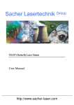
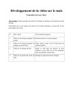
User Manual
Rev. 14.04
LDP-VRM-01-12-CA
- preliminary Manual -
1
How to use the Manual
Remark:
Remark:
Please refer to chapter Power dissipation for more details about the thermal power
losses during operation.
Before powering on your unit, read
read this manual thoroughly and make sure your
understood it fully.
Please pay attention to all safety warnings.
If you have any doubt or suggestion, please do not hesitate to contact us!
Absolute Maximum Ratings (destroying limits)
All Input Pins must not exceed the voltage range below zero (GND) and
beyond VCC
VCC Limit: Refer to table in chapter “Power Supply (#3)”
Peak Output-Current: 1.0 A
Operating temperature range: + 0 °C .. + 60 °C
Best performance operating temperature range: + 10 °C .. + 35 °C
Storage temperature range: - 20 °C .. + 70 °C
2
Dos and don’ts
Never ground any output connector.
Never use any grounded probes at the output.
Do not connect your oscilloscope to the output!
This will immediately destroy the driver and the probe!
Keep connecting cables between power supply and driver as well as the
connection between driver and laser diode as short as possible.
Please be aware that there might be hot surfaces, be careful not to
touch them!
3
How to get started
The basic settings (Scaling and BIAS-Current etc.) can be adjusted by potentiometer.
Bias set a dc output current up to 0.75 A without connecting input signal.
You need an additional waveform generator which has to be connected to the input terminal.
There is no AWG included within the driver!
Step #
What to do
Check
1
Solder a dummydummy-diode between LD+ and LDLD-,
alternatively make a short circuit there.
Refer to chapter “Test Load”
range of compliance voltage 0 V … 12
V.
2
Connect GND, VCC on Power connector
(power
ower source disabled).
Range of Vcc 12 V … 20 V.
Required max. current is about 1.2 A.
3
Connect waveform generator on input terminal
terminal
(no pulse before power supply enabled).
Refer to all chapters referencing Input
(Connector #2)
4
Enable the power source
5
Adjust scaling and bias
bias
See potentiometer for scaling an bias
6
Feed a signal on the input terminal. For
example 1Khz sine wave with 1V amplitude.
amplitude.
Make sure not to overload the laser
diode or the driver.
Range of input signal 0 V … 5 V.
7
Monitoring of the output current.
On current monitor you can measure a
signal comparable with the input
signal. Use an oscilloscope with a 1
MEG ohm termination. Scale 0.5 V/A.
8
Disable the input signal and turn off the power
power
source..
source
Remove the testtest-diode or bypass
bypass and assemble
assemble
the final laser diode.
9
Turn the power supply for the Vcc back on.
4
Range of Vcc 12 V … 20 V.
10
Feed a signal to the input terminal.
Make sure not to overload the laser
diode!
Required laser diode pin out
The LDP-VRM-01-12-CA is designed for the direct connection of almost any kind of
laser diode. The solder pads accept 2 and 3 terminal packaged Laser-Diodes.
Pitch of the LD+ and LD- connections is 3.5 mm.
Power driver block diagram
5
Description of the connectors of the LDP-VRM-01-12-CA
Connector
Function
#1
Power connector: Vcc
Screw terminal
#2
Power connector: GND for VCC and input
signal
Screw terminal
#3
Power connector: input signal
Screw terminal
#4
Jumper
Analog / Digital
#5
Monitor
Scale 0.5 V / A
6
Power supply (#1…3) and supply absolute maximum
ratings
Pin of conn. #3
1 Vcc (laser supply)
2 (GND)
3 (Input terminal)
Allowed range
12 V … 20 V
Best performance
3 V above
compliance
GND
-
GND
0V…5V
Destroying limit
25 V
+ 5.3 V
Input (#3)
The analogue set point signal is provided via connector #3. The output current
follows the input signal proportionally within the driver’s limitations (bandwidth,
max. current, rise time).
Jumper
The analogue input can be switched to an inverted digital input.
Set the jumper on left to activate the inverted digital input.
Current Monitor (#5)
The scale of current monitor is scaled with 0.5 V /A.
7
Description of the bias and scaling potentiometers
The bias potentiometer sets a dc output current up to 0.75 A which is added to the
input signal. Turn it right to increase the bias current.
The scaling potentiometer varies the scaling of input signal.
Turn it right to increase the scale from 0 A / V to 0.2 A / V.
Test Load
For the first test an appropriate test load may be assembled instead of the laser
diode. This test load can either be a short circuit or a schottky diode like the ES3C.
Please connect the test load only between anode and cathode (LD+ and LD-) and
prevent shorts to any other parts of the circuit.
Power Dissipation
The control of the driver reduces the power dissipation automatically to a minimum.
The driver doesn’t need to be cooled and have a maximum power dissipation of 2.2
W.
Mechanical Dimensions
The following dimensions are in millimetres (mm).
width 20
length 32
height 13
8