1
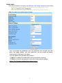
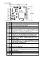
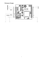
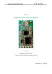
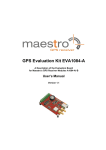
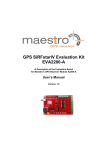
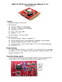
UART to TCP/IP core module User Manual (V 1.3)
(Model: IPM-C)
Feature:
1. Operation voltage: DC 3.3V or 5V.
2. Serial Interface
Interface : RS232 TTL compatibility.
Data Rate : 1200 bps up to 921600 bps
Characters : 5, 6, 7, 8
Parity : None, Even, Odd
Stop Bits : 1, 1.5
Control Signals : TxD, RxD, GND
3. Ethernet Interface
Ethernet Interface : 10Base-T, 100Base-TX
Ethernet Speed/Duplex : Auto-negotiation 10/100Mbps, Full/Half duplex
Protocols Supported : ARP, IP, UDP, TCP, BootP
Network Services : DHCP, DNS, PPPoE, TFTP, HTTP, UDP Broadcasting
Auto-MDIX : Yes
Default setting:
The module default IP address is 192.168.0.1, this module build-in a homepage
for setting, so user can change internal parameter setting by browser. The
operation voltage is DC 5V.
Operation voltage option:
The L3 default is connected, so the operation voltage is DC 5V, if you remove the
L3 and connect to L4, the operation voltage will be changed to DC 3.3V.
L4
L3
1
Quick start:
User can use browser and entry the URL(http://192.168.0.1/setting.htm) for setting.
About the web server setting page as below:
User can change any parameter, once the parameter was finished, user can
press the ‘Apply’ button, and new parameter can be saved to module
simultaneously the module will reboot.
The main page mainly provides two functions,
(1) Apply: to update the configuration value on the device server(s).
(2) Reset: to reset the configuration value to the factory default settings.
Notice: The ‘Firmware Update’ button doesn’t press.
2
Pin definitoin:
Pin Definition:
No.
Pin
Description
1
TX+ Transmit differential data output positive pin.
2
TX- Transmit differential data output negative.
3
RX+ Receive differential data input positive pin.
4
RX- Receive differential data input negative pin.
5
Link Link status LED indicator. This pin drives low continuously when the
Ethernet link is up and drives low and high in turn (blinking) when
Ethernet PHY is in receiving or transmitting state.
6~9
10
NC
-
13
nRST Chip reset input, active low. This is the external reset source used
to reset this chip. This input feeds to the internal power-on reset
circuitry, which then provides the main reset source of this chip.
SPD Ethernet speed LED indicator. This pin drives low when the
Ethernet PHY is in 100BASE-TX mode and drives high when in
10BASE-T mode.
FUX Full duplex and collision detected LED indicator. This pin drives low
when the Ethernet PHY is in full-duplex mode and drives high when
in half duplex mode. When in half duplex mode and the Ethernet PHY
detects collision, it will be driven low.
NC -
14
GND Ground
15
VDD DC 5V or 3.3V power input
16
GND Ground
11
12
17~18 NC
19
-
COM Don’t connector
20~28 NC
-
29
TXD UART serial transmit data.
30
RXD UART serial receive data.
3
Reference Design:
4