1
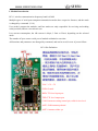
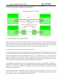
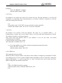
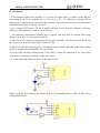
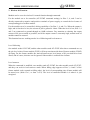
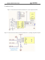
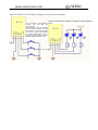
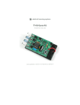
SEEED
WWW. SEEEDSTUDIO.COM
HC-11
434MHz Wireless Serial Port Module
Key Words
Half-duplex 80μA Idle Current
Number of Bytes Transmitted Unlimited to One time
Document No.: 20130910
WWW. SEEEDSTUDIO.COM
SEEED
Table of Contents
I. Module Introduction........................................................................................................................ 3
II. Wireless Serial Port Transparent Transmission..............................................................................4
III. Commands.....................................................................................................................................7
IV. Precautions.................................................................................................................................. 11
V. Wireless IO Function.................................................................................................................... 12
VI. Application Circuit......................................................................................................................13
VII. Electrical Characteristics...........................................................................................................17
VIII. Module Update.........................................................................................................................17
Attachment: Module History............................................................................................................ 17
WWW. SEEEDSTUDIO.COM
SEEED
I. Module Introduction
HC-11 wireless communication frequency band is 434M.
Multiple types of serial port transparent transmission modes have respective features, and the mode
is changed by command. (V1.8)
User needn’t program the modules, and four modes are only responsible for receiving and sending
serial port data, and are convenient to use.
Low current consumption; the idle current is 80μA, 3.5mA or 22mA, depending on the selected
mode.
The number of bytes sent to serial port of module unlimited to one time.
All functions and parameters are changed by command, and can be saved in case of power failure.
HC11 Pin Definition
VOC: 3.3V~5V
GND: Ground
RXD: TTL level input port
TXD: TTL level output port
CON: Parameter setting control pin, valid for low level
ANT1: POB antenna pedestal
ANT2: Antenna solder eye
SEEED
WWW. SEEEDSTUDIO.COM
II. Wireless Serial Port Transparent Transmission
Module Function Use Diagram
MCU, PC, or other
device
MCU PC, or other
device
Wired
Half-duplex
MCU, PC, or other
device
Module replaces wire and becomes
wireless communication
Module
Module
MCU PC, or other
device
Wirele
ss
(1) Simple description of working principle
When the device on the left of the above figure sends serial port data to module, and the RXD port
of the left module receives the serial port data, it will automatically send the data in the air by
means of radio wave. The right module can automatically receive the data, and restore, from TXD,
the serial port data originally sent by the left device. It is the same from right to left.
(2) Characteristics of serial port transparent transmission
The module has four types of serial port transparent transmission modes (this function is valid from
V1.8), expressed from FU1 to FU4. All modes are only responsible for receiving and sending serial
port data rather than wireless transmission, and are very convenient to use. Each mode has
respective characteristics, and details can be seen in the next sub-section. The default mode is FU1
mode, compatible with the previous versions. Different modes cannot transmit data to each other.
User could select the optimal mode according to practical circumstances.
The modules are usually used in pairs, and transmit data by means of half duplex (full duplex is
available for FU3 mode). The baud rate, communication channel and address of two paired modules
shall be set to be the same. Modules of different serial port modes, channels and addresses cannot
transmit data to each other.
Use the number of bytes continuously sent to serial port of module unlimited to one time (except for
FU2 mode). However, considering ambient interference, if thousands of data size is sent
continuously at a time, some number of bytes may be lost.
WWW. SEEEDSTUDIO.COM
SEEED
Working voltage of module is 3.3V~6V, and it can be directly connected to serial port of 3V, 5V
microcontroller.
The default parameters of modules are shown in the table below.
Parameter name
Baud rate of
Module address
Communication
serial port
channel
Parameter value 9,600 (8-bit data,
000
001
without check,
one stop bit)
Transmitting
power
P8 (10dBm)
After entering command mode, serial port transparent transmission function will not be valid. Then
the serial port is used to receive the command to change parameters. Parameter change can be seen
in Part III Command Instruction.
(3) Interpretation of serial port transparent transmission mode
FU1 mode
It is default mode of module, fully compatible with V1.7. Its current is 3.4mA.
FU2 mode
The idle current (which means that no serial port data are received and sent) of this mode is only
80μA averagely, but the time delay is very long, close to 400mS. In this mode, the baud rate of
serial port can only be 4,800, 2,400, or 1,200. Due to its long time delay, when sending serial port
data to module continuously, at most 245 bytes can be sent at a time.
Owing to its very low current consumption, this mode is suitable to low-power application.
FU3 mode
Its idle current is 23mA, much more than that of FU1 and FU2, but its transmission time delay is
reduced to be below 10mS. Accelerate question-and-answer application mode.
FU4 mode
V1.8 The lower the baud rate of serial port is, the farther the transmission distance is, but the
transmission time delay will be lengthened. Compared with the other three modes, its transmission
distance is farther.
In FU4 mode, when the baud rate of serial port is set to be below 9,600, although the transmission
distance is far, the transmission time delay will be much increased. In question-and-answer
application, one round trip takes more than 300mS.
SEEED
WWW. SEEEDSTUDIO.COM
The following gives some reference values of various modes (V1.8):
Mode
FU1
FU2
FU3
FU4
Idle current
3.5mA
80μA
22mA
22mA
Transmission
20mS
380mS
2mS
7 mS
time delay
Loopback test 31mS
8mS
22mS
time delay 1
Loopback test 31mS
time delay 2
18mS
40mS
Remark
Average value
Sending one
byte
Serial
port
baud
rate
9,600, sending
one byte
Serial
port
baud
rate
9,600, sending
ten bytes
Note: Loopback test time delay means the duration from the time of, after conducting short circuit
on TX and RX pins of one module and sending serial port data to the other module, starting to send
serial port data to the other module to the time that the returned data appear at TX pin of the other
module.
WWW. SEEEDSTUDIO.COM
SEEED
III. Commands
Command is used to set the module parameters and switch the module functions, and modification
of parameters and functions will not be lost in case of power failure.
(1) Command mode entering
1. Wireless serial port function command mode entering
The first way to enter: in normal use (energized), put Pin 5 in low level (pull down);
The second way to enter: disconnect power supply, first put Pin 5 in low level, then energize it
again, and 1S later enter the command mode;
Either of the above two ways can make the module enter AT command mode; release (not put in
low level), and exit from the command mode. If the module function is changed, it will be switched
to corresponding functional status.
While, the second way is different, and in V1.7 and previous versions, all parameters can be
restored to the default values, and in V1.8, the module enters AT in the serial port format of 9,600,
N, 1 constantly.
2. Wireless IO control function command mode entering
Only the second way can be used to enter the mode, but the parameters cannot be restored to the
default value and the module only enters AT mode. When exiting from the mode, the module will
switch to the status modified by the command.
(2) Command instruction
1. AT
Test command.
e.g.:
Send “AT” to module
And the module returns “OK”
2. AT+A
WWW. SEEEDSTUDIO.COM
SEEED
Change the module address, optional between 000 and 255, and it will be valid after exiting from
AT mode. The default value is 000.
e.g.: To set module address to be 012
Send “AT+A012” to module
And the module returns “OK-A012”
3. AT+B
Change the serial port baud rate, and it will be valid after exiting from AT mode. The baud rate can
be set to be 1,200, 2,400, 4,800, 9,600, 19,200, 38,400, 57,600, and 115,200. The default value is
9,600.
When using 115,200, continuously sending serial port data is not supported, and at most 245 bytes
can be sent at a time.
e.g.: To set serial port baud rate of module to be 19,200
Send “AT+B19200” to module
And the module returns “OK- B19200”
4. AT+C
Change wireless communication channel of module, optional from 001 to 127, and the default value
is 001. 0 cannot be omitted. If this value is too high, data might not be received, and about 20
channels are actually available, namely, from 001 to 020.
e.g.: To set module channel to be 015
Send “AT+C015” to module
And the module returns “OK- C015”
5. AT+Eyx
This command is used to set remote module. When remote module enters AT mode, the parameter y
will be changed to x, and it will be valid after exiting from AT mode. y is one among BAC,
respectively representing baud rate, address and channel, x value can be seen in the instruction of
commands Bx, Ax, and Cx. The meaning of returned value is as follows: EyE, parameter error; EyR,
set correctly; EyF, command error; Fail, connection failure. (E means external).
Example 1: Set remote module address to be 050
Send “AT+EA050” to module
And when the remote module enters AT mode, the module returns “EAR”, otherwise, it returns
“Fail”.
WWW. SEEEDSTUDIO.COM
SEEED
Example 2:
Send “AT+EB4800” to module
And the module returns “EBR”
6. AT+FCyy
Set module to be wireless IO control. See wireless IO part. The first parameter y can select M
(controller), S (controlled). The second parameter y can select F (follow), T (turnover). It will be
valid after exiting from AT mode.
e.g.:
One module sends “AT+FCMT” to set to controller (remote controller)
And the other module sends “AT+FCST” to set to be controlled
7. AT+FUx
Set module to be wireless serial port function. The value of x is optional within 1 ~ 4.
Characteristics of mode can be seen in Part II above. It will be valid after exiting from AT mode.
The default of module is serial port function.
Only when serial port function mode of two modules is set to be the same, can normal
communication be available.
F means function, and U means UART.
This command is available from V1.8.
e.g.: To set the module to be wireless serial port transparent transmission mode
Send “AT+FU1” to module
And the module returns “OK+FU1”
8. AT+GDPCxAx
This command has been invalid.
Obtain IO status of remote module. Only when remote module is changed by command AT+FCMF,
can reading succeed. CxAx is remote module channel and address such as C001A003. Among the
returned information, 3, 4, and 5 means Pin 3, 4, and 5, H means level, and L means low level.
When reading fails, the module returns Fail.
e.g.:
Send “AT+GDPC001A000” to module
And the module returns “GDPC001A000:3H, 4L, 5H”
Fail
WWW. SEEEDSTUDIO.COM
SEEED
9. AT+Px
Set transmitting power of module, x is optional from 1 to 8, respectively representing -30dBm,
-20dBm, -15dBm, -10dBm, 0dBm, 5dBm, 7dBm, and 10dBm; and the default is 8 (namely,
10dBm).
e.g.:
Send “AT+P6” to module
And the module returns “OK-P6”
10. AT+Ry
Obtain module parameters, y is any letter among B, A, C and P, respectively representing: baud rate,
address, channel and transmitting power.
Example 1:
Send “AT+RB” to module
And the module returns “B9600”
Example 2:
Send “AT+RA” to module
And the module returns “A001”
11. AT+RX
Obtain all common parameters of module. Return serial port mode, baud rate, channel, address, and
transmitting power in order. X is capital.
e.g.:
Send “AT+RX” to module
And the module returns “U1\r\nB9600\r\nC001\r\nA000\r\nP8\r\n”
12. AT+U
Set data check bit and stop bit of serial port communication
N: No check, O: odd; E: even.
1: Stop bit; 2: two bites; 3: 1.5 bits
e.g.: To set serial port format to odd check, and two stop bits
Send “AT+U02” to module
And the module returns “OK-U02”
WWW. SEEEDSTUDIO.COM
SEEED
13. AT+V
Return version information.
e.g.:
Send “AT+V” to module
And the module returns “HC-11_V1.3”.
14. AT+SLEEP
After receiving the command, the module enters sleep mode after exiting from AT, and this mode
doesn’t allow serial port data transmission. Then enter AT again, and the module will exit from
sleep mode automatically. Current consumption of sleep mode is 20μA. This command is available
from V1.8.
e.g.: When it’s not needed to transmit data, to save power,
Send “AT+SLEEP” to module
And the module returns “OK”
15. AT+RESET
Set serial port, channel and address to be default value.
e.g.:
Send “AT+RESET” to module
And the module returns “RESET_OK”.
16. AT+IV
Return version of internal update code of module. This command is available from V1.9.
e.g.:
Send “AT+IV” to module
And the module returns “I1”.
17. AT+UPDATE
Put the module in the status of waiting for software update.
After sending the command, the module will not respond to command any more, until it is
re-energized.
After serial port assistant sends this command, close the serial port, select file in HC11 updater, and
open the serial port. Then the module can update software version.
WWW. SEEEDSTUDIO.COM
SEEED
IV. Precautions
1. If the distance between two modules is very close (less than 0.5m), it would be better that the
transmitting power of two modules are set to be low, e.g. P1 ~ P3. Otherwise, receiving will be
saturated and communication between modules will fail. If the distance is only several centimeters,
communication cannot be ensured even more.
2. Don’t connect LED between TX line of module and power end to increase resistance. Otherwise,
serial port communication of module will be affected.
3. The following circumstances usually can be ignored, and they shall be noticed when using
dynamic parameters of microcontroller (MCU).
(1) After the device sends the serial port data of last byte to module, only after more than 28mS, can
the operation performance of entering AT mode be valid.
(2) After lowering and connecting Pin 5, command is sent to module only after 30mS. After pulling
up Pin 5, module can work normally only after 50Ms.
4. Except when entering command mode, CON (PIN 5) cannot be connected to low level at the
early stage of energizing (resetting) in other work mode.
e.g.: in the connecting method as shown in the figure below:
When energizing and working, the module will go to command mode to work. So the correct
connecting method is:
WWW. SEEEDSTUDIO.COM
SEEED
V. Wireless IO Function
Module can be set to be wireless IO control function through command.
For the module set to be controller (AT+FCMF command setting), its Pins 3, 4, and 5 can be
directly connected to negative and positive terminals of power supply, to control the level status of
corresponding pin of remote module.
For the module set to be controlled, driving capability of its Pins 3, 4, and 5 is: When the output is
high, and is forced to be low, the current of pin to ground is 18mA. When the level is low, Pins 3, 4
and 5 are connected to ground through an 180R resistance. Pay attention to reducing the output
current of IO port as much as possible, and if the output current is extremely high, normal work of
module cannot be ensured.
This function has two working modes: level following and level turnover.
Level following
One module sends AT+FCMF, and the other module sends AT+FCSF. After these commands are set,
the pin level value of latter module (FCSF) will keep consistent with that of former module (FCMF)
all along. For the former module, the interval between two level jumps of IO port shall be at least
50mS, and of course, this time can be ignored if the module is connected to a button.
Level turnover
When the command is modified, one module sends AT+FCMT, the other module sends AT+FCST,
and they can work in level turnover mode. When falling edge appears to Pins 3, 4 and 5 of the
former module (only respond to falling edge), the level of corresponding pins of latter module will
be turned over (from 0 to 1, or from 1 to 0). The level of controlled module is 0 when it is just
energized.
WWW. SEEEDSTUDIO.COM
SEEED
VI. Application Circuit
Figure I. Connection between Serial Port Module HC-11 and Computer Serial Port
Figure II. Connection between Wireless Serial Port Module HC-11 and Single Chip Microcomputer
The connection of Pin 5
can be removed if
parameters are not
WWW. SEEEDSTUDIO.COM
SEEED
Figure IV. Simple Test of Wireless IO Control
Send AT+FCMF (or AT+FCMT) to change to be wireless IO controller
Send AT+FCSF(or AT+FCMT) to change to be IO controlled
S1, S2 and S3 correspond to mode
control D1, D2 and D3
respectively.
For example, press S3, and D3
will be lit on; release S3, and
D3 will be lit off (the situation
of FCxT is: press and release
it, and the light will be lit on,
then press and release it again,
and the light will be lit off.)
SEEED
WWW. SEEEDSTUDIO.COM
Figure V. One-Master Multi-slave Communication Method
When MCU master sends serial port data, add a
byte of slave number before the data.
HC-11
MCU_ slave 1
After receiving serial port data, the slave will
judge whether the first byte of data is its number,
and if the first byte is its number, make response
and reply to the master; otherwise, make no
action.
MCU_ master
HC-11
After receiving serial port data, if slave 1 finds
that the number before data is ‘1’, process it and
send it back to the master.
HC-11
MCU_ slave 2
To communicate with slave 1, add ‘1’ before
serials port data, and to communicate with slave
2, add ‘2’.
After receiving serial port data, if slave 2 finds
that the number before data is ‘2’, process it and
send it back to the master.
HC-11
MCU_ slave 3
The same as slave 1 and slave 2
SEEED
WWW. SEEEDSTUDIO.COM
Figure VI. Combined Use of Bluetooth Module and 434M Wireless Module
Bluetooth
device
Mobile phone,
tablet PC, etc.
Bluetooth module
HC05, 06, etc
Wireless
module
HC11 or HC12
Single chip
microcompu
ter, etc
Serial port
device
Wireless
module
HC11 or HC12
This use method can increase the wireless communication distance between mobile phone and
single chip microcomputer to be 50m.
WWW. SEEEDSTUDIO.COM
SEEED
VII. Electrical Characteristics
Test power voltage is 3.32V. The following measured data are average values. The peek current
is 35mA.
1. Current consumption in wireless serial port function mode
Idle current in different function modes:
FU1: 3.5mA
FU2: 80uA
FU3: 22mA
FU4: 22mA
FCxx: 3.5mA
Idle means that the module receives neither serial port data nor wireless data. The maximum peek
value is 35mA in the state when module receives serial port data or wireless data.
2. Current consumption in wireless IO control mode
When IO port does not provide current for outside, the current is 3.5mA.