1
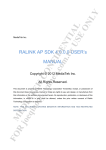
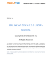
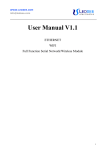
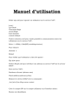
Wifi2UART Module User Manual
Version:0.1
Date: 2015.6.5
Wifi2UART Module
User Manual
Version
0.1
Issue date
2015/6/05
Initial Version
Changes
Remark
IMPORTANT
This document contains important Information and therefore
should not be disclosed to third parties without prior written consent of amazipoint technology Ltd.
Address
︰2F, No. 113, Zhongyang Rd., Xindian Dist., New Taipei City, Taiwan(R.O.C)
www.amazipoint.com
Signature:
Author:
Charles Ho
Reviewed by:
Approved by:
Copyright © amazipoint technology Ltd. All rights are reserved.
Remarks:
Page 1 of 25
Version:0.1
Date: 2015.6.5
Wifi2UART Module User Manual
1. Introduction
The Wifi2UART module is an embedded UART to WiFi/Ethernet (serial port to Wireless/Wired network)
conversion module. This product is based on the universal serial interface standard, built-in TCP/IP protocol
stack, enabling UART to WiFi/Ethernet conversions between the user serial port and wireless network (WiFi)
and Ethernet interfaces.
Through the Wifi2UART module, the traditional serial devices do not need to change their
configurations. Data from the UART port can be transmitted through the wireless and wired IP network, and
vice versa. It provides a solution for the users' serial devices to transfer serial port data via the IP network (or
the Internet).
Figure 1-1 shows the functional diagram of the Wifi2UART module, which provides end-to-end UART
connections from Wifi2UART module to remote Server or Client. (When Wifi2UART is a server, remote
clients will connect to it; when Wifi2UART is a client, it connects to a remote server).
Remote
Server
Wifi2UART
(Server or
Client)
UART
WiFi
UART
WAN
(Ethernet)
network
LAN
(Ethernet)
Figure 1-1
Remote
Client
UART
Functional Diagram of Wifi2UART Module
2. Technical specification
Items
Network standard
WiFi transmission rate
WiFi Channel number
WiFi Frequency
Specification
WiFi: IEEE 802.11n, 802.11g, 802.11b
Ethernet: IEEE 802.3, 802.3u
11n: up to 150 Mbps
11g: up to 54 Mbps
11b: uo to 11 Mbps
1 ~ 14
2.4 ~ 2.4835 GHz
Copyright © amazipoint technology Ltd. All rights are reserved.
Page 2 of 25
Wifi2UART Module User Manual
Interface
Serial baud rate
Service mode
Network protocol
TCP Server connection
Management
Network mode
Status indicator
Version:0.1
Date: 2015.6.5
2 Ethernet ports, 1 serial port for data, 1 serial port for console, an embedded WiFi
interface
1200 ~ 230400 bps
Server, Client, Not-In-Service
TCP/IP, UDP/IP
Up to 10 TCP clients can connect to Wifi2UART concurrently
AT-command via serial port, web management, web
software upgrade
There are four Network modes available:
1. (WiFi) AP Router Mode (WiFi AP and 2 Ethernet ports for WAN and LAN) (default
mode).
2. Single Ethernet WAN Mode.
3. (WiFi) AP Client Mode.
4. (WiFi) AP Mode.
1 status indicator
3. Quick Start
The Wifi2UART UART port uses 115200-8-N-1 (baud rate 115200 bps, 8 data bits, no parity check, 1
stop bit) as its default setting. Please connect your PC or serial device (with a terminal with the same
115200-8-N-1 setting) to the Wifi2UART UART port.
The Wifi2UART has two Operation Modes: AT Command Mode and Transparent Transmission Mode.
In AT Command Mode, Wifi2UART will treat incoming data from the UART port as AT commands; while in
Transparent Transmission Mode, Wifi2UART can send data from the UART port to WiFi or Ethernet ports
and vice versa. After power on, Wifi2UART is in Transparent Transmission Mode. Before you can use AT
commands to configure Wifi2UART, please use the following instructions to make it go to AT Command
Mode first (also see Figure 2-1 below):
1. send 7 characters: '+' '+' '+' 0x1B 0x1B 0x1B 0x1B, each character is separated to its
previous character by at least uartframetimeout ms. ( for uartframetimeout command and its setting, please
see section 5.2.21 for details).
2. the character which is previous to the first '+' character cannot be '+'.
When above two conditions are met, Wifi2UART will go to AT Command Mode. Now you can start
configuring Wifi2UART. You need to issue the commit AT command to save configurations to flash memory
(see section 5.2.23), so these settings will not be lost after power off.
Copyright © amazipoint technology Ltd. All rights are reserved.
Page 3 of 25
Version:0.1
Date: 2015.6.5
Wifi2UART Module User Manual
can’t be
‘+’
don’t
care
‘+’
‘+’
‘+’
(0x2B)
(0x2B)
(0x2B)
character
1
character
2
character
3
A
A
A
0x1B
character
4
A
0x1B
0x1B
character
5
character
6
A
A
0x1B
character
7
don’t
care
A
A: should be at least uartframetimeout ms
Figure 2-1
Criteria to enter AT Command Mode
After finishing configuring Wifi2UART, you can use the leave_at AT command to leave the AT
Command Mode (and go to Transparent Transmission Mode, please see section 5.2.22 for that command) or
just reboot Wifi2UART to go to Transparent Transmission Mode.
The AT command configurations can be divided to two categories: Network-related configurations and
Service-related configurations. Network-related configurations are for network infrastructure like which
interface will be enabled, interface's IP address, DHCP function, WiFi settings, etc.; while Service-related
configurations are for sending converted UART data between servers and clients like UART baud rate, the
TCP or UDP protocol used, which role Wifi2UART to play (server or client), etc. A complete configuration
includes Network-related configuration and Service-related configuration. Please refer to 'section 5 - AT
Commands' for details on AT commands functions and format.
Wifi2UART's factory default settings can be found in Appendix A.
There are many configuration scripts in Appendix which can be used to facilitate your configuration
process. For Network-related configuration, please see Appendix C; Service-related configuration, please see
Appendix D.
4. Function Description
Wifi2UART can transmit the serial port data to other network interfaces and vice versa. In section 4.1
Network Mode, various network modes, each with different network interfaces enabled, will be described in
detail. Wifi2UART can play the role as a server or a client, and communicate with its counterpart using TCP
or UDP protocol. In section 4.2 Service Mode with TCP or UDP protocol, various combinations of service
modes and protocols will be described.
4.1 Network Mode
Copyright © amazipoint technology Ltd. All rights are reserved.
Page 4 of 25
Wifi2UART Module User Manual
Version:0.1
Date: 2015.6.5
There are four Network Modes for Wifi2UART, each with different network interfaces enabled/disabled.
UART data can be sent to those enabled network interfaces and vice versa. Beside the UART to WiFi/Ethernet
conversion function, Wifi2UART module itself can also function as a network device.
4.1.1 AP Router Mode
In this mode the Ethernet WAN, Ethernet LAN and WiFi AP interfaces are up and running. Wifi2UART's
network function is like an AP Router. Serial (UART) data can be sent to these interfaces, and vice versa. We
can enable the DHCP client function on the WAN interface or configure its IP statically. The Ethernet LAN
and WiFi AP interfaces are on the same (network) bridge, and we can enable/disable the DHCP server on
these interfaces.
4.1.2 Single WAN Mode
In this mode only the Ethernet WAN interface is up and running. Serial (UART) data can be sent to this
interface, and vice versa. We can enable DHCP client on the WAN interface or configure its IP statically.
4.1.3 AP Client Mode
In this mode only the AP Client interface is up and running. Serial (UART) data can be sent to this
interface, and vice versa. An AP Client can connect to other WiFi AP. The AP Client interface can be treated
like a (WiFi) WAN, and we can enable DHCP client on this interface or configure its IP statically.
4.1.4 AP Mode
In this mode only the WiFi AP interface is up and running. Serial (UART) data can be sent to this
interface, and vice versa. A WiFi AP allows other WiFi stations to connect to it, and we can enable/disable the
DHCP server on this interface.
4.2 Service Mode with TCP or UDP protocol
There are three Service Mode for Wifi2UART: Server Mode, Client Mode and Not-In-Service Mode.
The default Service Mode is Not-In-Service, which means the serial (UART) to WiFi/Ethernet conversion
function is not in service. In the Not-In-Service Mode, the Wifi2UART is an ordinary network device (AP
Router, etc.). If you want it to start doing UART to WiFi/Ethernet conversion service, you must change it to
Server mode (to be connected by remote clients) or Client mode (to connect to a remote Server) so
Wifi2UART knows where to send UART data to (and where to get data from). Please see 'section 5.2.13
service_mode' on how to change service mode in details.
4.2.1 TCP Server
In this mode the Wifi2UART listens on all of its network interfaces (with a specific TCP port number,
which is set by the service_port command) for connection requests from remote TCP clients. The Wifi2UART
allows up to 10 concurrent TCP connections. The Wifi2UART will send its UART data to all TCP clients and
all data from TCP clients to its UART port. If there is no data traffic (from TCP server to client, or from TCP
client to server) in a connection for a period of time (set by service_timeout command), Wifi2UART will
terminate that connection.
4.2.2 TCP Client
In this mode the Wifi2UART will connect to a remote TCP server (with the server's IP and port number
set by service_ip and service_port commands respectively). If auto reconnection function is enabled (by the
tcp_auto command), Wifi2UART will keep trying to reconnect to the TCP server automatically once it has
detected the connection is terminated.
Copyright © amazipoint technology Ltd. All rights are reserved.
Page 5 of 25
Wifi2UART Module User Manual
Version:0.1
Date: 2015.6.5
4.2.3 UDP Server
In this mode the Wifi2UART waits incoming UDP packets on all of its interfaces (with a specific UDP
port number, which is set by the service_port command). Wifi2UART will record the latest UDP client's IP
and port number. Data from UDP clients will be sent to Wifi2UART's UART port, while Wifi2UART's UART
data will be sent to its latest UDP client.
4.2.4 UDP Client
In this mode the Wifi2UART will send its UART data to a remote UDP server (with the server's IP and
port number set by service_ip and service_port commands respectively). Data received from Wifi2UART's
UDP server will be sent to its UART port.
5. AT Commands
5.1 AT command general description
To configure Wifi2UART, the AT command format is at+<command_name>=xxx\r (xxx are the
configuration characters, and \r is the Carriage Return character(0x0D)). No space is allowed in the format.
Wifi2UART will echo the AT command you send (without the \r) and append it with a space character and
then "OK" or "Error" to indicate success or failure of that AT command. Finally a \r will be appended at the
end of the response. In Figure 5-1 if we set Net Mode to 5 in the first AT command, Error will be sent back
because net_mode can't be set to 5 (only 1~4 are allowed). OK will be sent back after we successfully set Net
Mode to 1 in the second AT command.
Figure 5-1
AT Command for configuration
To query the current Wifi2UART configurations, the AT command format is at+<command_name>=?\r
(question mark character and the Carriage Return character). No space is allowed in the format. Wifi2UART
will echo the AT command you send (without the \r) and append it with a space and then the response to the
query. Finally a \r will be appended at the end of the response. In Figure 5-2, '1' is the response to the Net
Mode query.
Figure 5-2
AT Command for query
Copyright © amazipoint technology Ltd. All rights are reserved.
Page 6 of 25
Wifi2UART Module User Manual
Version:0.1
Date: 2015.6.5
Some commands can ask Wifi2UART to do special actions. The AT command format is
at+<command_name>=1\r (character '1' and the Carriage Return character '\r'). Wifi2UART will echo the
AT command you send (without \r) and append it with a space character and then "OK" or "Error" at the end
to indicate success or failure of that AT command. Finally a \r will be appended at the end of the response. In
Figure 5-3, OK is sent back to indicate the AT command is accepted successfully (to ask Wifi2UART to save
configurations to flash memory).
Figure 5-3
AT Command for action
In the table (Table 5.1 AT Command List) below, those commands that can be used to configure settings
are indicated by 'S' in the function column; those to query current configurations are indicated by 'Q'; those to
ask for actions are indicated by 'A'.
The AT command configurations can be divided to two categories: Network-related configurations and
Service-related configurations. Those Network-related configurations will take effect after reboot; while
Service-related configurations will take effect after reboot or after the service_restart AT command is sent. In
the table below, those commands that can be used to set Network-related configurations are indicated by 'Net'
in the category column; those to set Service-related configurations are indicated by 'Srvc'.
command_name
net_mode
wifi_ap
wifi_ap_client
channel
wan_dhcpc
wan_ip
wan_dns
lan_ip
dhcpd
dhcpd_ip
dhcpd_dns
dhcpd_time
service_mode
function
S,Q
S,Q
S,Q
S,Q
S,Q
S,Q
S,Q
S,Q
S,Q
S,Q
S,Q
S,Q
S,Q
category
Net
Net
Net
Net
Net
Net
Net
Net
Net
Net
Net
Net
Srvc
service_ip
S,Q
Srvc
service_port
service_pro
service_timeout
S,Q
S,Q
S,Q
Srvc
Srvc
Srvc
tcp_auto
S,Q
Srvc
uart
S,Q
Srvc
description
Network Mode configuration
WiFi AP configuration
WiFi AP Client configuration
WiFi channel configuration
WAN port DHCP client enable/disable configuration
WAN port static IP configuration
WAN port DNS Server configuration
LAN port static IP configuration
LAN/WLAN port DHCP Server enable/disable configuration.
DHCP Server leasing IP addresses configuration
DHCP Server leasing DNS configuration
DHCP Server lease time configuration in second
Service Mode configuration. There are three modes: Server
Mode, Client Mode, or Not-In-Service Mode.
Remote Server's IP configuration (when Wifi2UART is itself
in Client Mode)
Port number (for TCP and UDP connection) configuration
Protocol configuration. TCP or UDP.
TCP connection timeout configuration in second (it is used
when Wifi2UART is in TCP Server Mode)
TCP auto connection configuration (it is used when
Wifi2UART is in TCP Client Mode)
UART baud rate, data bits, parity check, stop bit configuration
Copyright © amazipoint technology Ltd. All rights are reserved.
Page 7 of 25
Wifi2UART Module User Manual
uartframelen
uartframetimeout
leave_at
S,Q
S,Q
A
commit
service_restart
A
A
default
reboot
ver
A
A
Q
Srvc
Srvc
Version:0.1
Date: 2015.6.5
UART frame length configuration in byte
UART frame timeout configuration in mini second (ms)
Ask Wifi2UART to leave AT Command Mode (and go to
Transparent Transmission Mode)
Ask Wifi2UART to save configurations to flash memory.
Ask Wifi2UART to restart the UART to WiFi/Ethernet
conversion service (send/receive UART data to/from remote
Servers or Clients).
Ask Wifi2UART to set to factory default configurations.
Ask Wifi2UART to reboot.
Query the current software version.
Table 5.1 AT Command List
5.2 AT command list
This section describes every AT command's function, format and parameters in detail. To query current
settings, the format is always at+<command name>=?\r (see Appendix B - script to get current
configurations)
5.2.1 net_mode
Function:
Set the Network Mode. Each mode has different network interfaces enabled.
Format:
at+net_mode=<net mode>\r
Parameter:
net mode, please see below table:
value
description
1
AP Router Mode. serial to WiFi AP and 2 Ethernet ports (WAN and LAN)
conversion. It is the default mode.
2
Single WAN Mode. serial to one Ethernet port (WAN) conversion
3
AP Client Mode. serial to WiFi AP Client conversion. This AP Client can link to
another WiFi AP.
4
AP Mode. serial to WiFi AP conversion. Other WiFi stations can link to this AP.
5.2.2 wifi_ap
Function:
WiFi AP configurations.
Format:
at+wifi_ap=<ssid>,<encrypt type>,<password> \r
Parameter:
ssid: wireless network SSID (Maximum length: 20 characters.)
encrypt type: authentication and encryption, please see below table:
value
description
none
Open network
wep_open
wep encryption open authentication
,
Copyright © amazipoint technology Ltd. All rights are reserved.
Page 8 of 25
Wifi2UART Module User Manual
wpa_tkip
wpa_aes
wpa2_tkip
wpa2_aes
wpawpa2_tkip
wpawpa2_aes
Version:0.1
Date: 2015.6.5
wpa tkip
wpa_aes
wpa2 tkip
wpa2 aes
wpa/wpa2 tkip
wpa/wpa2 aes
password: password in ASCII format (Maximum length: 13 characters) (note: for wep_open encrypt type,
the password should be 5 or 13 characters)
5.2.3 wifi_ap_client
Function:
WiFi AP Client configurations. The configurations shows which remote AP (its SSID, encrypt type and
password) this AP Client is intended to link to.
Format:
at+wifi_ap_client=<ssid>,<encrypt type>,<password> \r
Parameter:
ssid: wireless network SSID (Maximum length: 20 characters.)
encrypt type: authentication and encryption, please see below table:
value
description
none
Open network
wep_open
wep encryption open authentication
wpa_tkip
wpa tkip
wpa_aes
wpa_aes
wpa2_tkip
wpa2 tkip
wpa2_aes
wpa2 aes
,
password: password in ASCII format (Maximum length: 13 characters) (note: for wep_open encrypt type,
the password should be 5 or 13 characters)
5.2.4 channel
Function:
WiFi channel selection
Format:
at+channel=<channel>\r
Parameter:
channel: 1 ~ 14
5.2.5 wan_dhcpc
Function:
WAN port DHCP client enable
Format:
at+wan_dhcpc=<enable>\r
Parameter:
enable, please see below table:
value
description
Copyright © amazipoint technology Ltd. All rights are reserved.
Page 9 of 25
Wifi2UART Module User Manual
0
1
Version:0.1
Date: 2015.6.5
DHCP client disabled, WAN port will use static IP configuration
DHCP client enabled, WAN port will get IP configuration from a DHCP Server
5.2.6 wan_ip
Function:
Set the static WAN port IP. When WAN port DHCP client is disabled, static IP configuration will be
used.
Format:
at+wan_ip=<ip>,<mask>,<gateway>\r
Parameter:
ip: IP address
mask: Subnet mask
gateway: Default gateway IP address
5.2.7 wan_dns
Function:
Set the static WAN port DNS. When WAN port DHCP client is disabled, static DNS configuration will
be used.
Format:
at+wan_dns=<dns 1>,<dns 2>\r
Parameter:
dns 1: First DNS IP address
dns 2: Second DNS IP address
5.2.8 lan_ip
Function:
Set the static LAN port IP. The configuration is valid only when Wifi2UART's Network Mode is mode 1
(AP Router Mode, default mode) or mode 4 (WiFi AP Mode). Please refer to "4.1 Network Mode".
Format:
at+lan_ip=<ip>,<mask>\r
Parameter:
ip: IP address
mask: Subnet mask
5.2.9 dhcpd
Function:
Set the DHCP server on LAN port or WLAN (Wireless LAN) port. The configuration and the following
dhcpd-related configurations (5.2.10 dhcpd_ip, 5.2.11 dhcpd_dns, 5.2.12 dhcpd_time) will be used only
when Wifi2UART's Network Mode is mode 1 (AP Router Mode, default mode) or mode 4 (WiFi AP Mode).
Please refer to "4.1 Network Mode".
Format:
at+dhcpd=<enable>\r
Parameter:
enable, please see below table:
value
description
Copyright © amazipoint technology Ltd. All rights are reserved.
Page 10 of
25
Wifi2UART Module User Manual
0
1
Version:0.1
Date: 2015.6.5
DHCP server disabled
DHCP server enabled
5.2.10 dhcpd_ip
Function:
DHCP Server's leasing IP addresses. Also refer to section 5.2.9 dhcpd.
Format:
at+dhcpd_ip=<ip start>,<ip end>,<mask>,<gateway>\r
Parameter:
ip start: start of the IP addresses that Server will lease to DHCP clients
ip end: end of the IP addresses that Server will lease to DHCP clients
mask: subnet mask that Server will provide to DHCP clients
gateway: default gateway that Server will provide to DHCP clients
5.2.11 dhcpd_dns
Function:
DNS information that DHCP Server will provide to its clients. Also refer to section 5.2.9 dhcpd.
Format:
at+dhcpd_dns=<dns 1>,<dns 2>\r
Parameter:
dns 1: First DNS IP address
dns 2: Second DNS IP address
5.2.12 dhcpd_time
Function:
DHCP Server's IP lease time in second. Also refer to section 5.2.9 dhcpd.
Format:
at+dhcpd_time=<time>\r
Parameter:
time: lease time in second (maximum length is 7 digits)
5.2.13 service_mode
Function:
Set the Service Mode of Wifi2UART
Format:
at+service_mode=<service mode>\r
Parameter:
service mode, please see below table:
value
description
none
Wifi2UART is Not-In-Service (or the UART to WiFi/Ethernet conversion is not
functioning)
server
Wifi2UART plays the role as a Server in the UART to WiFi/Ethernet conversion.
client
serial to WiFi AP-Client. This AP-Client can link to another WiFi AP.
5.2.14 service_ip
Copyright © amazipoint technology Ltd. All rights are reserved.
Page 11 of
25
Wifi2UART Module User Manual
Version:0.1
Date: 2015.6.5
Function:
When Wifi2UART is configured as a client, the service_ip configuration tells Wifi2UART what the
remote Server's IP address is.
Format:
at+service_ip=<remote server's ip>\r
Parameter:
remote server's ip: remote Server's IP address
5.2.15 service_port
Function:
When Wifi2UART is configured as a client, the service_port configuration tells Wifi2UART what the
remote Server's TCP or UDP port number is. When Wifi2UART is configured as a server, the service_port
configuration will be used by Wifi2UART as its TCP or UDP port number.
Format:
at+service_port=<port>\r
Parameter:
port: port number (maximum port number is 65535)
5.2.16 service_pro
Function:
Set the protocol used by Wifi2UART to connect to remote Servers or Clients.
Format:
at+service_pro=<protocol>\r
Parameter:
protocol, please see below table:
value
description
tcp
TCP protocol
udp
UDP protocol
5.2.17 service_timeout
Function:
When Wifi2UART is configured as a TCP Server, it will terminate the TCP connection to a client if there
is no traffic (from Server to client and vice versa) between them for more than service_timeout seconds. If this
setting is 0, it means never timeout.
Format:
at+service_timeout=<service timeout>\r
Parameter:
service timeout: timeout in seconds (maximum length is 6 digits). 0 for never timeout.
5.2.18 tcp_auto
Function:
When Wifi2UART is configured as a TCP Client and tcp_auto is set to 1, it will try to auto reconnect to
the remote TCP server when disconnection is detected by Wifi2UART.
Format:
Copyright © amazipoint technology Ltd. All rights are reserved.
Page 12 of
25
Wifi2UART Module User Manual
Version:0.1
Date: 2015.6.5
at+tcp_auto=<enable>\r
Parameter:
enable, please see below table:
value
description
0
TCP auto reconnection is disabled
1
TCP auto reconnection is enabled
5.2.19 uart
Function:
Set the serial port configurations.
Format:
at+uart=<baud>,<data>,<parity>,<stop>\r
Parameter:
baud: baud rate (could be 1200 bps, 2400 bps, 4800 bps, 9600 bps, 19200 bps, 38400 bps, 57600 bps,
115200 bps, or 230400 bps)
data: data bits (could be 5, 6, 7, 8 bits)
parity: parity check (could be n for no parity check, 1 for odd parity check or 2 for even parity check)
stop: stop bits (could be 1 or 2 bits)
5.2.20 uartframelen
Function:
Set the serial port frame length in byte. Wifi2UART will send serial (UART) data to WiFi/Ethernet
interfaces after it receives at least uartframelen byte of data from the serial port. Otherwise Wifi2UART will
wait until uartframetimeout timeout (see section 5.2.21 uartframetimeout) to send data to WiFi/Ethernet
interfaces.
Format:
at+uartframelen=<frame length>\r
Parameter:
frame length: frame length in bytes. (maximum length is 999 bytes)
5.2.21 uartframetimeout
Function:
Set the serial port frame timeout in ms. Wifi2UART will send UART data to WiFi/Ethernet after it
receives at least uartframelen byte of data from the serial port (see section 5.2.20 uartframelen). Otherwise
Wifi2UART will wait until uartframetimeout timeout expires to send UART data to WiFi/Ethernet.
The minimum value is 50 ms and every increasing step is 10 ms.
Format:
at+ uartframetimeout =<frame timeout>\r
Parameter:
frame timeout: timeout in ms. (minimum value is 50 ms, every increasing step is 10 ms , maximum value
is 999990 ms)
5.2.22 leave_at
Function:
Ask Wifi2UART to leave AT Command Mode (and go to Transparent Transmission Mode) (after you
Copyright © amazipoint technology Ltd. All rights are reserved.
Page 13 of
25
Wifi2UART Module User Manual
Version:0.1
Date: 2015.6.5
have finished configuring Wifi2UART).
Format:
at+leave_at=1\r
Parameter:
N.A.
5.2.23 commit
Function:
Ask Wifi2UART to save configurations to flash memory. You must issue this AT command to save new
configurations to flash memory, otherwise new configurations will be lost after power off.
Format:
at+commit=1\r
Parameter:
N.A.
5.2.24 service_restart
Function:
After you change Service-related configurations (refer to section 5.1 AT command general description),
you can issue this command to ask Wifi2UART to restart server/client to client/server connection and doing
UART to WiFi/Ethernet conversion based on these new configurations.
Format:
at+service_restart=1\r
Parameter:
N.A.
5.2.25 default
Function:
Ask Wifi2UART to set to factory default configurations. Wifi2UART's factory default settings can be
found in Appendix A.
Format:
at+default=1\r
Parameter:
N.A.
5.2.26 reboot
Function:
Ask Wifi2UART to reboot.
Format:
at+reboot=1\r
Parameter:
N.A.
5.2.27 ver
Function:
Copyright © amazipoint technology Ltd. All rights are reserved.
Page 14 of
25
Wifi2UART Module User Manual
Version:0.1
Date: 2015.6.5
Query the current software version..
Format:
at+ver=?\r
Parameter:
N.A.
Appendix A - factory default configurations
command_name
net_mode
wifi_ap
function default configuration
S,Q
1
S,Q
RT5350_AP,none
wifi_ap_client
S,Q
channel
wan_dhcpc
wan_ip
S,Q
S,Q
S,Q
wan_dns
S,Q
lan_ip
S,Q
dhcpd
dhcpd_ip
S,Q
S,Q
dhcpd_dns
S,Q
dhcpd_time
service_mode
service_ip
service_port
service_pro
service_timeout
tcp_auto
uart
S,Q
S,Q
S,Q
S,Q
S,Q
S,Q
S,Q
S,Q
description
AP Router Mode
For WiFi AP:
SSID is RT5350_AP
Encrypt type is none (Open network)
No initial settings.
For WiFi AP Client:
No default configuration. Users need to
configure it by themselves.
1
WiFi channel number: 1
1
WAN port DHCP client mode is enabled.
192.168.1.1,255.255.255.0, WAN port static IP:
192.168.1.254
IP is 192.168.1.1
Mask is 255.255.255.0
Gateway is 192.168.1.254
168.95.1.1,8.8.8.8
WAN port static DNS Server:
First DNS is 168.95.1.1
Second DNS is 8.8.8.8
10.10.10.254,255.255.255.0 LAN port static IP:
IP is 10.10.10.254
Mask is 255.255.255.0
1
LAN/WLAN DHCP Server is enabled.
10.10.10.100,10.10.10.200, DHCP Server leasing IP addresses:
255.255.255.0,10.10.10.254 Start IP is 10.10.10.100
End IP is 10.10.10.200
Mask is 255.255.255.0
Gateway is 10.10.10.254
168.95.1.1,8.8.8.8
DHCP Server leasing DNS:
First DNS is 168.95.1.1
Second DNS is 8.8.8.8
86400
DHCP Server lease time: 86400 seconds.
none
Not-In-Service Mode
192.168.1.254
Remote Server's IP: 192.168.1.254
8080
TCP or UDP port number is 8080.
tcp
Protocol configuration: TCP
0
0 means never timeout
1
TCP client auto reconnection is enabled
115200,8,n,1
UART baud rate, data bits, parity check, stop
Copyright © amazipoint technology Ltd. All rights are reserved.
Page 15 of
25
Wifi2UART Module User Manual
uartframelen
uartframetimeout
leave_at
commit
service_restart
default
reboot
ver
S,Q
S,Q
A
A
A
A
A
Q
64
50
N.A.
N.A.
N.A.
N.A.
N.A.
01.00.01
Version:0.1
Date: 2015.6.5
bit: 115200, 8, no parity check, 1
UART frame length is 64 bytes
UART frame timeout is 50 ms
current software version: 01.00.01
You can use the script in Appendix B to get these factory default configurations:
at+net_mode=? 1
at+wifi_ap=? RT5350_AP,none
at+wifi_ap_client=? No initial settings. Or previous settings are illegal
at+channel=? 1
at+wan_dhcpc=? 1
at+wan_ip=? 192.168.1.1,255.255.255.0,192.168.1.254
at+wan_dns=? 168.95.1.1,8.8.8.8
at+lan_ip=? 10.10.10.254,255.255.255.0
at+dhcpd=? 1
at+dhcpd_ip=? 10.10.10.100,10.10.10.200,255.255.255.0,10.10.10.254
at+dhcpd_dns=? 168.95.1.1,8.8.8.8
at+dhcpd_time=? 86400
at+service_mode=? none
at+service_ip=? 192.168.1.254
at+service_port=? 8080
at+service_pro=? tcp
at+service_timeout=? 0
at+tcp_auto=? 1
at+uart=? 115200,8,n,1
at+uartframelen=? 64
at+uartframetimeout=? 50
at+ver=? 01.00.01
(please note Wifi2UART will append a \r at the end of every response)
Appendix B - script to get current configurations
To each query command, Wifi2UART will echo the AT command you send (without the \r) and append it
with a space and then the response to the query. Finally a \r will be appended at the end of response.
In the below AT commands, please make sure every AT command must end with \r.
at+net_mode=?
at+wifi_ap=?
at+wifi_ap_client=?
at+channel=?
at+wan_dhcpc=?
Copyright © amazipoint technology Ltd. All rights are reserved.
Page 16 of
25
Wifi2UART Module User Manual
Version:0.1
Date: 2015.6.5
at+wan_ip=?
at+wan_dns=?
at+lan_ip=?
at+dhcpd=?
at+dhcpd_ip=?
at+dhcpd_dns=?
at+dhcpd_time=?
at+service_mode=?
at+service_ip=?
at+service_port=?
at+service_pro=?
at+service_timeout=?
at+tcp_auto=?
at+uart=?
at+uartframelen=?
at+uartframetimeout=?
at+ver=?
(please make sure every AT command must end with '\r')
Appendix C - scripts to configure Network-related settings
A complete configuration includes Network-related configuration and Service-related configuration (see
Appendix D). Please combine these two configurations according to your requirement.
Before you start configuration by using AT commands, please follow instructions in section 3 Quick
Start to go to AT Command mode first.
C.1 AP Router Mode configuration script
-- with WAN port DHCP client enabled and LAN port DHCP server enabled
Network
WAN (Ethernet) AP
AP Client
LAN (and WLAN)
Mode
AP Router DHCP client
SSID: RT5350_AP, encrypt
N.A.
DHCP server enabled
enabled
type: none,
Channel 1 is used.
at+net_mode=1
at+wifi_ap=RT5350_AP,none
at+channel=1
at+wan_dhcpc=1
at+lan_ip=10.10.10.254,255.255.255.0
at+dhcpd=1
at+dhcpd_ip=10.10.10.100,10.10.10.200,255.255.255.0,10.10.10.254
at+dhcpd_dns=168.95.1.1,8.8.8.8
at+dhcpd_time=86400
(please make sure every AT command must end with '\r')
The Wifi2UART's response on serial port will be:
at+net_mode=1 OK
Copyright © amazipoint technology Ltd. All rights are reserved.
Page 17 of
25
Wifi2UART Module User Manual
Version:0.1
Date: 2015.6.5
at+wifi_ap=RT5350_AP,none OK
at+channel=1 OK
at+wan_dhcpc=1 OK
at+lan_ip=10.10.10.254,255.255.255.0 OK
at+dhcpd=1 OK
at+dhcpd_ip=10.10.10.100,10.10.10.200,255.255.255.0,10.10.10.254 OK
at+dhcpd_dns=168.95.1.1,8.8.8.8 OK
at+dhcpd_time=86400 OK
(please note Wifi2UART will append a \r at the end of every response)
After you have configured Wifi2UART successfully, please save configurations to flash memory by:
at+commit=1
(please make sure every AT command must end with '\r')
Then reboot Wifi2UART for new Network-related configurations to take effect. This can be done by:
at+reboot=1
(please make sure every AT command must end with '\r')
C.2 AP Router Mode configuration script
-- with WAN port DHCP client disabled and LAN port DHCP server enabled
Network Mode WAN (Ethernet)
AP
AP Client
AP Router
DHCP client
SSID: RT5350_AP, encrypt N.A.
disabled, use static IP type: none,
settings
Channel 1 is used.
LAN (and WLAN)
DHCP server enabled
at+net_mode=1
at+wifi_ap=RT5350_AP,none
at+channel=1
at+wan_dhcpc=0
at+wan_ip=192.168.1.1,255.255.255.0,192.168.1.254
at+wan_dns=168.95.1.1,8.8.8.8
at+lan_ip=10.10.10.254,255.255.255.0
at+dhcpd=1
at+dhcpd_ip=10.10.10.100,10.10.10.200,255.255.255.0,10.10.10.254
at+dhcpd_dns=168.95.1.1,8.8.8.8
at+dhcpd_time=86400
(please make sure every AT command must end with '\r')
The Wifi2UART's response on serial port will be:
at+net_mode=1 OK
at+wifi_ap=RT5350_AP,none OK
at+channel=1 OK
at+wan_dhcpc=0 OK
at+wan_ip=192.168.1.1,255.255.255.0,192.168.1.254 OK
at+wan_dns=168.95.1.1,8.8.8.8 OK
at+lan_ip=10.10.10.254,255.255.255.0 OK
at+dhcpd=1 OK
at+dhcpd_ip=10.10.10.100,10.10.10.200,255.255.255.0,10.10.10.254 OK
at+dhcpd_dns=168.95.1.1,8.8.8.8 OK
Copyright © amazipoint technology Ltd. All rights are reserved.
Page 18 of
25
Version:0.1
Date: 2015.6.5
Wifi2UART Module User Manual
at+dhcpd_time=86400 OK
(please note Wifi2UART will append a \r at the end of every response)
After you have configured Wifi2UART successfully, please save configurations to flash memory by:
at+commit=1
(please make sure every AT command must end with '\r')
Then reboot Wifi2UART for new Network-related configurations to take effect. This can be done by:
at+reboot=1
(please make sure every AT command must end with '\r')
C.3 Single WAN Mode configuration script
-- with WAN port DHCP client enabled
Network Mode
WAN (Ethernet)
Single WAN
DHCP client enabled
AP
N.A.
AP Client
N.A.
LAN
N.A.
at+net_mode=2
at+wan_dhcpc=1
(please make sure every AT command must end with '\r')
The Wifi2UART's response on serial port will be:
at+net_mode=2 OK
at+wan_dhcpc=1 OK
After you have configured Wifi2UART successfully, please save configurations to flash memory by:
at+commit=1
(please make sure every AT command must end with '\r')
Then reboot Wifi2UART for new Network-related configurations to take effect. This can be done by:
at+reboot=1
(please make sure every AT command must end with '\r')
C.4 Single WAN Mode configuration script
-- with WAN port DHCP client disabled
Network Mode WAN (Ethernet)
AP
Single WAN
DHCP client disabled, use N.A.
static IP settings
AP Client
N.A.
LAN
N.A.
at+net_mode=2
at+wan_dhcpc=0
at+wan_ip=192.168.1.1,255.255.255.0,192.168.1.254
at+wan_dns=168.95.1.1,8.8.8.8
(please make sure every AT command must end with '\r')
The Wifi2UART's response on serial port will be:
at+net_mode=2 OK
at+wan_dhcpc=0 OK
Copyright © amazipoint technology Ltd. All rights are reserved.
Page 19 of
25
Wifi2UART Module User Manual
Version:0.1
Date: 2015.6.5
at+wan_ip=192.168.1.1,255.255.255.0,192.168.1.254 OK
at+wan_dns=168.95.1.1,8.8.8.8 OK
(please note Wifi2UART will append a \r at the end of every response)
After you have configured Wifi2UART successfully, please save configurations to flash memory by:
at+commit=1
(please make sure every AT command must end with '\r')
Then reboot Wifi2UART for new Network-related configurations to take effect. This can be done by:
at+reboot=1
(please make sure every AT command must end with '\r')
C.5 AP Client Mode configuration script
-- with WAN port DHCP client enabled
Network Mode WAN (AP Client plays AP
the role as WAN)
AP Client
DHCP client enabled
N.A.
AP Client
LAN
Ask AP Client to link to an AP (whose
SSID is remote_AP), with encrypt
type: wep_open, and password 12345.
Channel 1 is used.
N.A.
at+net_mode=3
at+wan_dhcpc=1
at+wifi_ap_client=remote_AP,wep_open,12345
at+channel=1
(please make sure every AT command must end with '\r')
The Wifi2UART's response on serial port will be:
at+net_mode=3 OK
at+wan_dhcpc=1 OK
at+wifi_ap_client=remote_AP,wep_open,12345 OK
at+channel=1 OK
(please note Wifi2UART will append a \r at the end of every response)
After you have configured Wifi2UART successfully, please save configurations to flash memory by:
at+commit=1
(please make sure every AT command must end with '\r')
Then reboot Wifi2UART for new Network-related configurations to take effect. This can be done by:
at+reboot=1
(please make sure every AT command must end with '\r')
C.6 AP Client Mode configuration script
-- with WAN port DHCP client disabled
Network Mode WAN (AP Client will
AP
play the role as WAN)
AP Client
DHCP client disabled,
N.A.
AP Client
LAN
Ask AP Client to link to an AP (whose
N.A.
Copyright © amazipoint technology Ltd. All rights are reserved.
Page 20 of
25
Version:0.1
Date: 2015.6.5
Wifi2UART Module User Manual
use static IP settings
SSID is remote_AP), with encrypt type:
wep_open, and password 12345.
Channel 1 is used.
at+net_mode=3
at+wan_dhcpc=0
at+wan_ip=192.168.1.1,255.255.255.0,192.168.1.254
at+wan_dns=168.95.1.1,8.8.8.8
at+wifi_ap_client=remote_AP,wep_open,12345
at+channel=1
(please make sure every AT command must end with '\r')
The Wifi2UART's response on serial port will be:
at+net_mode=3 OK
at+wan_dhcpc=0 OK
at+wan_ip=192.168.1.1,255.255.255.0,192.168.1.254 OK
at+wan_dns=168.95.1.1,8.8.8.8 OK
at+wifi_ap_client=remote_AP,wep_open,12345 OK
at+channel=1 OK
(please note Wifi2UART will append a \r at the end of every response)
After you have configured Wifi2UART successfully, please save configurations to flash memory by:
at+commit=1
(please make sure every AT command must end with '\r')
Then reboot Wifi2UART for new Network-related configurations to take effect. This can be done by:
at+reboot=1
(please make sure every AT command must end with '\r')
C.7 AP Mode configuration script
-- with LAN port DHCP client enabled
Network Mode
WAN
AP
AP
N.A.
SSID: RT5350_AP,
encrypt type: wep_open,
password: 1234567890123.
Channel 1 is used.
AP Client
N.A.
LAN (WLAN)
DHCP server enabled
at+net_mode=4
at+wifi_ap=RT5350_AP,wep_open,1234567890123
at+channel=1
at+lan_ip=10.10.10.254,255.255.255.0
at+dhcpd=1
at+dhcpd_ip=10.10.10.100,10.10.10.200,255.255.255.0,10.10.10.254
at+dhcpd_dns=168.95.1.1,8.8.8.8
at+dhcpd_time=86400
(please make sure every AT command must end with '\r')
The Wifi2UART's response on serial port will be:
Copyright © amazipoint technology Ltd. All rights are reserved.
Page 21 of
25
Wifi2UART Module User Manual
Version:0.1
Date: 2015.6.5
at+net_mode=4 OK
at+wifi_ap=RT5350_AP,wep_open,1234567890123 OK
at+channel=1 OK
at+lan_ip=10.10.10.254,255.255.255.0 OK
at+dhcpd=1 OK
at+dhcpd_ip=10.10.10.100,10.10.10.200,255.255.255.0,10.10.10.254 OK
at+dhcpd_dns=168.95.1.1,8.8.8.8 OK
at+dhcpd_time=86400 OK
(please note Wifi2UART will append a \r at the end of every response)
After you have configured Wifi2UART successfully, please save configurations to flash memory by:
at+commit=1
(please make sure every AT command must end with '\r')
Then reboot Wifi2UART for new Network-related configurations to take effect. This can be done by:
at+reboot=1
(please make sure every AT command must end with '\r')
Appendix D - scripts to configure Service-related settings
A complete configuration includes Network-related configuration (see Appendix C) and Service-related
configuration. Please combine these two configurations according to your requirement.
Before you start configuration by using AT commands, please follow instructions in section 3 Quick
Start to go to AT Command mode first.
D.1 TCP Server configuration script
Service protocol Service IP
Service port
Mode
server
TCP
N.A.
8080
(listen on all
(TCP port
interfaces' IP) number)
TCP client auto
reconnection
N.A.
TCP service
timeout
0 (never
timeout)
UART
115200,8,n,1
at+service_mode=server
at+service_port=8080
at+service_pro=tcp
at+service_timeout=0
at+uart=115200,8,n,1
at+uartframelen=64
at+uartframetimeout=50
The Wifi2UART's response on serial port will be:
at+service_mode=server OK
at+service_port=8080 OK
at+service_pro=tcp OK
at+service_timeout=0 OK
at+uart=115200,8,n,1 OK
at+uartframelen=64 OK
Copyright © amazipoint technology Ltd. All rights are reserved.
Page 22 of
25
Wifi2UART Module User Manual
Version:0.1
Date: 2015.6.5
at+uartframetimeout=50 OK
(please note Wifi2UART will append a \r at the end of every response)
After you have configured Wifi2UART successfully, please save configurations to flash memory by:
at+commit=1
(please make sure every AT command must end with '\r')
For Service-related configurations to take effect, it can be done by (1) asking Wifi2UART to restart service
and then leave AT Command Mode (to go to Transparent Transmission Mode):
at+servive_restart=1
at+leave_at=1
or (2) rebooting Wifi2UART:
at+reboot=1
(please make sure every AT command must end with '\r')
D.2 TCP Client configuration script
Service protocol Service IP
Service port
Mode
client
TCP
192.168.1.254 8080
(remote
(TCP port
server's IP)
number)
TCP client auto
reconnection
Yes
TCP service
timeout
N.A.
UART
115200,8,n,1
at+service_mode=client
at+service_ip=192.168.1.254
at+service_port=8080
at+service_pro=tcp
at+service_timeout=0
at+tcp_auto=1
at+uart=115200,8,n,1
at+uartframelen=64
at+uartframetimeout=50
The Wifi2UART's response on serial port will be:
at+service_mode=client OK
at+service_ip=192.168.1.254 OK
at+service_port=8080 OK
at+service_pro=tcp OK
at+service_timeout=0 OK
at+tcp_auto=1 OK
at+uart=115200,8,n,1 OK
at+uartframelen=64 OK
at+uartframetimeout=50 OK
(please note Wifi2UART will append a \r at the end of every response)
After you have configured Wifi2UART successfully, please save configurations to flash memory by:
at+commit=1
(please make sure every AT command must end with '\r')
Copyright © amazipoint technology Ltd. All rights are reserved.
Page 23 of
25
Wifi2UART Module User Manual
Version:0.1
Date: 2015.6.5
For Service-related configurations to take effect, it can be done by (1) asking Wifi2UART to restart service
and then leave AT Command Mode (to go to Transparent Transmission Mode):
at+servive_restart=1
at+leave_at=1
or (2) rebooting Wifi2UART:
at+reboot=1
(please make sure every AT command must end with '\r')
D.3 UDP Server configuration script
Service protocol Service IP
Service port
Mode
server
UDP
N.A. (use all 8080
interfaces'
(UDP port
IP)
number)
TCP client auto
reconnection
N.A.
TCP service
timeout
N.A.
UART
115200,8,n,1
at+service_mode=server
at+service_port=8080
at+service_pro=udp
at+uart=115200,8,n,1
at+uartframelen=64
at+uartframetimeout=50
The Wifi2UART's response on serial port will be:
at+service_mode=server OK
at+service_port=8080 OK
at+service_pro=udp OK
at+uart=115200,8,n,1 OK
at+uartframelen=64 OK
at+uartframetimeout=50 OK
(please note Wifi2UART will append a \r at the end of every response)
After you have configured Wifi2UART successfully, please save configurations to flash memory by:
at+commit=1
(please make sure every AT command must end with '\r')
For Service-related configurations to take effect, it can be done by (1) asking Wifi2UART to restart service
and then leave AT Command Mode (to go to Transparent Transmission Mode):
at+servive_restart=1
at+leave_at=1
or (2) rebooting Wifi2UART:
at+reboot=1
(please make sure every AT command must end with '\r')
D.4 UDP Client configuration script
Copyright © amazipoint technology Ltd. All rights are reserved.
Page 24 of
25
Wifi2UART Module User Manual
Service
Mode
client
protocol Service IP
UDP
Service port
192.168.1.254 8080
(remote
(UDP port
server's IP)
number)
TCP client auto
reconnection
N.A.
TCP service
timeout
N.A.
Version:0.1
Date: 2015.6.5
UART
115200,8,n,1
at+service_mode=client
at+service_ip=192.168.1.254
at+service_port=8080
at+service_pro=udp
at+uart=115200,8,n,1
at+uartframelen=64
at+uartframetimeout=50
The Wifi2UART's response on serial port will be:
at+service_mode=client OK
at+service_ip=192.168.1.254 OK
at+service_port=8080 OK
at+service_pro=udp OK
at+uart=115200,8,n,1 OK
at+uartframelen=64 OK
at+uartframetimeout=50 OK
(please note Wifi2UART will append a \r at the end of every response)
After you have configured Wifi2UART successfully, please save configurations to flash memory by:
at+commit=1
(please make sure every AT command must end with '\r')
For Service-related configurations to take effect, it can be done by (1) asking Wifi2UART to restart service
and then leave AT Command Mode (to go to Transparent Transmission Mode):
at+servive_restart=1
at+leave_at=1
or (2) rebooting Wifi2UART:
at+reboot=1
(please make sure every AT command must end with '\r')
Copyright © amazipoint technology Ltd. All rights are reserved.
Page 25 of
25