1
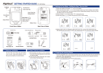
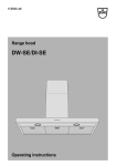
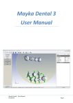
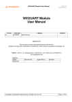
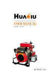
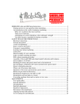
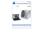
Manual
DDS
DE
Operating Instructions
CNC Milling Machines DS2000
valid from August 2013
This technical documentation is valid from August 2013.
ver1334
2
Content
5.0 Running the machine
1.0 Legend
1.1 Explanation of safety message text
4
5.1 Operating the machine
22
1.2 Classification of signal words
4
5.2 Air extraction
22
1.3 Symbols and hints
4
5.3 Synchronous spindle SFS 300P
23
1.4 Instruction symbols
5
5.4 Tools
23
5.5 Changing the blanks
25
5.6 Procedure after a power failure
26
2.0 General safety messages
2.1 Supplemental directives
6
2.2 Safety messages
6
2.3 Intended use of the machine
8
3.0 General information
3.1 About this manual
9
3.2 Machine components
10
3.3 Technical data
11
3.3.1
Basic system
11
3.3.2
Rotary axes
11
3.3.3
Spindle13
12
3.3.4
Tool changer
12
3.3.5Controller
12
3.4
Manufacturing software
13
3.5
Scope of delivery
14
6.0 Maintenance and cleaning
6.1 Internal cleaning
27
6.2 Collet chuck cleaning
28
6.3 External cleaning (housing)
29
6.4 Maintenance compressed air
30
6.5 Calibration
31
6.6 Maintenance table
32
7.0 Disposal
33
4.0 Installation
4.1 Placement
15
4.2 Setting up the machine
16
4.3 Connecting the compressed air
17
4.3.1
Connecting the service unit
18
4.3.2
Setting the air pressure
19
4.4 Connecting the air extraction
19
4.5 Software installation
20
3
Legend
1.1 Explanation of safety message text
Legend
General warning text. Failure to comply with the information given in this text can lead to serious injury.
Nature and source of a hazardous situation
CAUTION
Possible consequences!
Advice to avoid the hazardous situation
1.2 Classification of signal words
DANGER indicates a hazardous situation which, if not avoided, will result in death or
DANGER
serious injury.
WARNING
WARNING indicates a hazardous situation which, if not avoided, could result in death or
serious injury.
CAUTION
CAUTION indicates a hazardous situation which, if not avoided, could result in minor or
moderate injury.
NOTICE
NOTICE is used to address practices not related to physical injury. It indicates situations
that can lead to material damage of the product or the environment.
1.3 Symbols and hints
i
background
information
list
4
Important
Operating instructions and other important information
Hint
Information to make work easier
Legend
1.3 Instruction symbols
Legend
requirement
M1.
first action (M stands for manually)
S2.
second action in the software (S stands for Software)
M3.
third action (M stands for manually)
result
5
General safety messages
General safety messages
2.1 Supplemental directives
Read this manual before you start the machine. Follow the listed safety messages to avoid
risks and possible major injuries.
The users have to be informed about the intended use of the machine (page <?>). The
safety messages indicated in this document have to be followed.
Check the machine and especially the protective devices for possible damages. Damaged
safety devices or parts thereof must, if not stated otherwise in the user manual, be repaired
or replaced by authorised service personnel.
Besides a maintenance of the machine is executed, it may only be operated with a closed
front cover and with the safety interlock being shut. It is forbidden to disable the present
safety devices or to set them out of use.
Keep children and animals away from the machine. Don’t leave the machine running
unattended, if other people have access to the machine. Use of the machine in maintenance
mode may only be done by service personnel, that is trained by DentaSwiss to use the
machine in maintenance mode.
Please be aware of the information about the choice of tools and the adjustment of tool
parameters (see chapter 5.4).
2.2 Safety messages
DANGER
Use of damaged cables
Danger to life due to an electric shock!
Disconnect the machine from any electrical source and prevent the machine from being
restarted.
Contact the service department.
Replace damaged cables only with original spare parts.
Troubleshooting while the machine is running
Danger to life due to an electric shock!
DANGER
Consult the service department, before you clear the malfunction on your own.
Disconnect the machine from any electrical source and prevent the machine from being
restarted.
6
General safety messages
General safety messages
WARNING
Operation of the machine in maintenance mode with open front cover
Risk of injury through cuts and bruises! Hazards through ejected chips!
Use of the machine in maintenance mode may only be done by service personnel, that
is trained by DentaSwiss to use the machine in maintenance mode.
Don’t grasp into the working chamber, while the machine is moving and while the milling
job is processed.
All persons within reach of the machine have to wear protective glasses when the machine is run with an open front cover.
WARNING
Processing harmful material
Respiratory diseases due to inhalation of harmful materials!
Process material only when the air extraction is running.
Only use suited materials, that are harmless when the air extraction is working.
Use a suction device with an extra-fine particle filter.
WARNING
Loud noise from the machine
Hearing damage due to loud noise!
Change the milling conditions. Ensure that the workpiece is fixed properly and check
the values for the rotational speed, the cutting depth, the feed rate and the tool endurance. Also check the material you use.
Change the tools regularly.
Wear ear protection during processing, if loud noises can’t be avoided.
WARNING
Open pneumatic connections
Danger through loose pneumatic parts conducting compressed air!
Separate the machine from the compressed air supply.
Consult the service department.
CAUTION
Disorder in the working environment
Trip hazard!
Keep the working environment clean.
Store the extra equipment like the vacuum cleaner or the wet grinding module in a safe
place.
7
General safety messages
General saftey messages
CAUTION
Ergonomics in the working environment
Subsequent damage due to constant malposition!
Adjust the working environment ergonomically.
Pay attention to keep the seat height, the monitor position and the exposure to light ideally.
CAUTION
Inserting milling tools
Cuts through sharp tool cutting edges!
Grab milling tools only at the shaft, not at the tool tip.
Take care not to cut yourself or others while handling with the tool.
2.3 Intended use of the machine
The machines of the type CAM 5-S1 Impression have been designed for easy to medium milling works in
the field of dental technology. It has to be considered that the machine cannot withstand all powers that
can possibly occur during operation.
The machines are designed to process the following materials:
wax
most of the plastic materials (e.g. PMMA)
composites
zirconium oxide
non-precious alloys (CoCr - based)
The machine can get damaged, if it is used for another purpose than described above. The protective
devices may not be avoided or turned off.
The instructions of this manual have to be followed and the maintenance procedures have to be executed
as described.
The machine may only be operated with original equipment from DentaSwiss or with authorised equipment,
to keep up the safety of the product and the warranty of the machine. The user carries the risk of damage
to the machine if non-authorised equipment is used.
The warranty expires, if you modify the machine or take off the housing without a written agreement of the
DentaSwiss service department.
8
General information
General information
3.1 About this manual
This manual will enable you to use the dental milling machine CAM 5-S1 Impression as well as the accessory equipment safely and reliably. In this manual we want to advise you especially about the possible sources
of danger that may come from the systems and to emphasise the correct use of the systems. Accordingly,
we request you to read this manual attentively and to follow the advice given.
Keep this manual near the machine and ensure that everybody, who is working with the machine, has access to this manual.
i We appreciate every feedback and suggestion for improvement, so that we can continuously improve
our product and the associated documentation. If you have questions or suggestions, please refer to
your reseller.
9
General information
General information
3.2 Machine components
front cover with safety contact and safety
interlock
synchronous spindle SFS 300P
working chamber
4th/5th axis: fixing device for round universal blanks Ø 98 mm and a thickness
from 10 to 30 mm
opening for dust extraction
liquid outlet for wet grinding
A axis: rotation range of 360 degrees
pressure key for tool measurement
changing station for 16 tools
B axis: rotation range of ± 30 degrees
Illustration 1: Machine components DS2000
10
General information
General information
3.3 Technical data
3.3.1 Basic system
dimensions (W/D/H): approximately 490 x 445 x 540 mm
five-axes mechanism; positioning range (x/y/z): 140 x 98 x 76 mm
precise ball screw spindles for the 3 linear axes with 4 mm pitch
repetition accuracy ± 0.003 mm
complete housing of working chamber with closable front cover including a front lid switch and safety
interlock
working chamber illumination
prepared air extraction option through hose connection sleeve and switching output at the side of the
housing (requirements: external vacuum cleaner)
underpressure sensor for monitoring the air extraction
prepared wet grinding option through air extraction opening and switching output at the side of the
housing (requirements: wet grinding module by DentaSwiss)
blank dimensions: Ø 98.5 mm (± 0.2 mm), with groove
blank thickness: 10 mm to 30 mm
weight: approximately 75 kg
maximum compressed air consumption of about 80 litres per minute
3.3.2 Rotary axes
rotary axes free from backlash with Harmonic-Drive® mechanism
rotational angle: 360 degrees (A axis), ± 30 degrees (B axis)
automatic measurement of rotary axes and automatic axis compensation for exact results
integrated fixing device for round universal blanks
11
General information
General information
3.3.3 Spindle
synchronous spindle with rotational speeds up to 60,000 RPM
nominal power under continuous load (S1): 300 Watts
maximal power (Pmax): 600 Watts
4-fold bearing
hybrid ceramic ball bearings
pneumatic collet chuck 3 mm
3 liquid nozzles for wet grinding
cone cleaning
3.3.4 Tool changer
automatic tool changer for 16 tools
automatic tool length detection and tool breakage monitoring via pressure key
diamond-coated tools can be used
compressed air monitoring
3.3.5 Controller
five-axis microstep controller
simultaneous control of 5 axes
great smoothness and high accuracy due to microstep operation
high processing speed due to exponential acceleration slopes and automatic change-over to full step
mode
look-ahead feature for continuous velocity along the path
optional Ethernet interface
included control software for a comfortable output of the data which has been generated by the post
processor
speed limitations: 0.003 mm/s up to 55 mm/s
12
General information
General information
3.4 Manufacturing software
i To calculate the milling paths you need to create a file in the STL format from your CAD program. All
important parameters for the respective material are included in the software package DentalCAM. Operation with external CAM programs is possible, if there is a post processor for the respective program.
If you want to use an external CAM software contact DentaSwiss to clarify, if there is already a post
processor for your CAM software or if a new post processor has to be written for your program. The
machine is controlled with the included software DentalCNC.
i For operating the manufacturing software, please refer to the corresponding software manual.
13
General information
General information
3.5 Scope of delivery
Illustration 2: Scope of delivery DS2000
A
B
M
C
D
E
F
L
G
H
I
J
K
A 1 power supply cord
B 1 USB connection cable
C 1 set of replacement screws for the tool changer plate and the fixing device
D 2 measuring pins
E 1 drill 2.8 mm for the tool changer inserts
F 1 USB dongle
G 2 tool changer rubber inserts
H 1 hexagon socket screw key 3 mm to change the blanks in the fixing device
I 1 key for emergency release of the front cover
J 1 hose connection for external vacuum cleaner
K 1 service unit for compressed air
L pneumatic hose Ø 6 mm
M 1 spindle service set
CNC machining system DS2000 (not pictured)
manual DS2000 (not pictured)
software manual (not pictured)
software license DentalCAM including control software – current version downloadable at
http://www.dentaswiss.com/CAMSW
i If you are using an external CAM software only the control software DentalCNC is included in the scope
of delivery.
14
Installation
4.1 Placement
Installation
The following requirements have to be considered to choose the right machine location:
firm and even surface, has to carry the weight of the machine (approximately 75 kg)
room temperature ideally between 18° Celsius and 25° Celsius
relative air moisture maximum 80 %, non-condensing
alternating current source with 90 – 240 V and 50 – 60 Hz
The machine needs to have an adequate distance to the wall on the right side of the machine (seen from
the front), so that the ventilation holes are not blocked (at least 10 cm distance). On the left side and on
the back of the machine needs to be enough distance, so that you can reach all machine connections
easily.
NOTICE
Plug the machine’s power cord in a separately fused circuit current or ensure that no devices are connected that cause heavy voltage fluctuation when switched on (air compressor, suction unit). Heavy voltage fluctuations can disturb the control and cause a failure of
the system. Don’t use multiple sockets for the power supply of the machine.
liquid inlet for external pump of the
wet grinding module, Ø 6 mm
pneumatic connection, Ø 6 mm
main power switch
connection for optional Ethernet interface
USB 2.0 connection
switching output for external pump of the
wet grinding module
switching output for external suction unit
power supply 90 – 240 V AC, 50/60 Hz
air extraction opening
liquid drainage with blind plug for the wet
grinding module
Illustration 3: Connection panel DS2000
15
Installation
4.2 Setting up the machine
Installation
M1.
Unwrap the milling machine. Please keep the packaging for possible further service shipments.
M2.
Connect the service unit via the standard pneumatic connection plug with your compressed
air supply (see also chapter 4.3)
Important
The pneumatic hose (blue hose) must be inserted in the blue marked connection (on the
top left of the connection panel, see Illustration 3). It may not be inserted in the stainless
steel connection, since the machine doesn’t start without compressed air!
M3.
Check the displayed air pressure value on the manometer. If the pressure is not between 6
and 8 bar, reset the pressure value (see chapter 4.3.2).
M4.
Connect the manufacturing computer to the machine via the USB connection respectively
via the Ethernet port.
M5.
Put the vacuum hose with the hose connection in the air extraction opening at the side of
the machine (see also chapter 4.4).
M6.
Insert the dongle in a USB port of the manufacturing computer.
M7.
Connect the power cord to the machine.
Important
M8.
Plug the machine’s power cord in a separately fused circuit current or ensure that no devices are connected that cause heavy voltage fluctuation when switched on (air compressor, suction unit). Heavy voltage fluctuations can disturb the control and cause a failure of
the system. Don’t use multiple sockets for the power supply of the machine.
The front cover is closed.
M9.
Start the machine with the main power switch.
16
Installation
4.3 Connecting the compressed air
Installation
The spindle SFS 300P needs a pneumatic connection. The spindle uses the compressed
air to control the collet chuck during the automatic tool change. It is also used to produce
sealing air, that prevents dirt from entering into the spindle. The maximum air consumption
of the machine is about 80 litres per minute.
NOTICE
Important
The scope of delivery contains a service unit for the compressed air supply. You can use it
to regulate the incoming compressed air to the machine. The built-in water separator containing a 5-micron fine filter prevents moisture or dirt from getting into the machine.
The incoming compressed air has to be dry and free of oil according to ISO 8573-1, since
the water separator can filter only small amounts. Wet compressed air can lead to bearing
damage and electrical damage of the spindle.
Air purity according to ISO 8573-1
Solid contamination
Water content
Overall oil content
class 3 class 4
class 5
Filtration degree better than 5 microns for solids
Maximum pressure dew point +3 °C
Maximum oil content 1 mg/m³
The compressed air supply has to provide at least 6 bar during operation of the machine.
17
Installation
4.3.1 Connecting the service unit
Installation
The service unit can be mounted to the housing or connected directly to the compressed
air supply. You need to make sure that the service unit is visible during operation so that a
regular control is possible. In the following text the mounting to the housing is explained. If
you connect the service unit directly to the compressed air supply, please regard only the
steps M3. to M5.
NOTICE
The service unit has to be installed vertically (see Illustration 4). The water separator doesn’t
work, if the service unit is not installed vertically!
M1
Remove the two blind screws under the vent holes at the side of the milling machine.
M2
Mount the service unit vertically with the included cylinder head screws (see Illustration 5
on page 23).
CAUTION
Connect the maintenance unit to the machine before you connect the maintenance unit to
the compressed air supply. Otherwise risk of injury occurs through leaking compressed air
or lashing pneumatic hoses.
M3
Cut a piece of the delivered pneumatic hose (Ø 6 mm) in the desired length.
M4
Connect the pneumatic connection on the right side of the maintenance unit to the pneumatic connection of the machine.
M5
Connect the compressed air supply to the standard pneumatic connection plug on the left
side of the maintenance unit.
knob for pressure regulation
cylinder head screws
standard pneumatic
connection plug
pneumatic connection to the machine
Ø 6 mm
manometer
water separator
discharging screw
Illustration 4: Maintenance unit: air pressure setting and control
18
Installation
4.3.2 Setting the air pressure
Installation
Hint
Setting the air pressure is only necessary, if the displayed pressure on the manometer is
not between 6 and 8 bar.
The maintenance unit is connected to your compressed air supply.
M1
Pull the knob on top of the maintenance unit a little bit.
M2
Set the pressure (turning the knob toward “+” increases the pressure, turning the knob
toward “–” decreases the pressure), until the displayed value is at least 6 bar.
M3
Push the knob down again.
The air pressure is set and cannot be changed inadvertently.
4.4 Connecting the air extraction
Important
The vacuum cleaner that you use has to be suitable for your application (extra-fine particle
filter for processing harmful material etc.).
Empty the dust bag of your air extraction regularly and replace the possibly existing extrafine particle filter in regular intervals.
Read the manual of your air extraction carefully and follow the advice given.
M1
Plug the hose connection with the air extraction hose in the opening at the side of the
machine.
M2
Connect the optional switching unit to the switching output at the side of the machine (see
Illustration 3).
M3
Connect the air extraction to the power supply respectively connect it to the switching unit
and connect the switching unit to the power supply (see Illustration 5).
19
Installation
4.5 Software installation
Installation
Installation and operation of the control software and the milling machine is only possible
when the dongle is connected to the manufacturing computer.
The manufacturing computer is running and connected to the machine.
S1
Insert the delivered dongle in a USB port of the manufacturing computer.
S2
Download the installation file of the software fromhttp://www.dentaswiss.com/CAMSW in
the download sector.
S3
Unzip the downloaded file.
S4
Start the file setup.exe and follow the advice of the installation program.
i
Further advice for the software installation is given in the software manual.
Please check our website regularly, if new software updates are available.
20
Installation
Installation
Dongle
housing vent holes
USB connection of the
manufacturing computer
power supply
blind plug of
safety interlock
external compressed
air source
maintenance unit
power supply
switching output
connection for optional
Ethernet interface
switching unit
(optional)
vacuum cleaner for dry milling (optional)
regard the separate manual for
connecting the wet grinding
module
power supply
hose connection
Illustration 5: Overview of the machine connections DS2000
21
Running the machine
Running the machine
5.1 Operating the machine
Make sure that all cables and hoses have been connected correctly and turn on the machine with the main power switch on the side of the machine.
For a milling job you only need the blanks which you want to use as well as the appropriate tools. As the machine is operated through the software, you can find further details on
handling the machine in the software manual.
The machine is equipped with a safety contact and a safety interlock for the front cover.
When the safety interlock is shut, the front cover cannot be opened during a milling operation.
Important
The machine may only be operated when the safety interlock is shut.
5.2 Air extraction
NOTICE
Operate the machine only with the air extraction turned on and make sure, that the air
extraction opening is not blocked. If the air extraction is not working properly, material
chips can reach the sensitive parts of the machine like the bearings or the ball screws and
damage them!
The model CAM 5-S1 Impression is prepared for air extraction with an external industrial
vacuum cleaner. For this purpose, the machine is equipped with an opening for the hose
connection as well as a switching output for automatically switching the suction unit at the
housing side.
For operating the air extraction unit you need the provided hose connection and an external vacuum cleaner.
The machine is equipped with an underpressure sensor for monitoring the air extraction.
Make sure, that the air extraction is running and the air extraction opening is not blocked.
The integrated working chamber sealing air concept prevents milling dust and chippings
from entering into the mechanics and electronics of the machine and reduces wear and
maintenance efforts.
22
Running the machine
Running the machine
5.3 Synchronous spindle SFS 300P
WARNING
NOTICE
For the operation, installation and maintenance of the spindle follow the regulations for the
prevention of accidents. Improper handling or operations differing from the intended use of
the machine greatly reduce the safety of usage!
The synchronous spindle SFS 300P is a high precision device that may never be subject to
any form of raw force like strikes!
Keep in mind that the values for the immersion depth and the feed rate are not too high
during operation. This can lead to damage of the workpiece and tilting of the tool. By that
the spindle can take irreparable damages. If you work with the DentalCAM software, the
software automatically calculates the optimal parameters.
Do not use unbalanced tools (single tooth cutters, gravers) at high rotational speeds. Such
an imbalance can be heard by a loud running noise and puts a great strain on the ball bearings of the spindle.
5.4 Tools
CAUTION
Never touch a tool at the tip. Otherwise cutting injuries may occur.
In order to insert or exchange tools move the machine to the basic position using the software. Insert the tool with the tip downwards into the tool changer inserts. Make sure that
you put the tool in the position, that you assigned in the software.
Hint
Usage of original tools is recommended, since the tools are designed by DentaSwiss especially for the machine and the designated milling operation.
Important
The tools used for Cobalt-chrome blanks are shorter than tools for other materials. Therefore only Cobalt-chrome blanks with a thickness of maximal 16 mm can be used on the
machine!
If you should use tools from other manufacturers, please regard the following specifications.
For storing the tool in the tool changer an unmachined shank with a length of at least 7 mm
is required.
23
Running the machine
Running the machine
NOTICE
A retaining ring has to be installed as a stop ring into the existing slot. Install only retaining
rings according to DIN 471-A3!
Make sure that the tools are put straight in the tool changer. All inserted tools must suit the
positions stored in the software. Otherwise the tool or the workpiece may get damaged.
Only tools with a shank diameter of 3 mm may be used. Don’t use tools, where the cutting
edge diameter is higher than the shank diameter (Ø 3 mm). Don’t use tools with a cutting
edge diameter higher than 2.5 mm for the tool changer, otherwise the tool changer inserts
get damaged.
40
tool shaft
3 mm
0,5 mm
min. 7 mm
max. 40 mm
2,7 mm
13 mm
11,9 mm
1,1 x 0,4 m m
tool tip
max.
2,5 mm
Illustration 6: Tool dimensions for DS2000
24
Running the machine
Running the machine
5.4 Changing the blanks
The blanks are tightened in the fixing device by a fixing disc (see Illustration 7).
S1.
Move the machine to the basic position.
M2.
Loosen the four screws at the fixing disc with a hexagon socket screw key (3 mm), until the
fixing disc can be moved.
M3.
Turn the fixing disc and take it off. You can leave the screws in the fixing device.
The blank can be changed.
M4.
Insert the fixing disc and turn it until the screws are in the middle of the holes.
M5.
Tighten the screws crosswise.
blank
screws
fixing disc
Abbildung 7: Fixing device DS2000
25
Running the machine
Running the machine
5.6 Procedure after a power failure
If there is a short power failure, it is enough to turn the machine back on again. In this case
the machine references and moves to the basic position.
If there is a longer power failure or a malfunction of the power wire you can open the safety
interlock with an emergency key to take the blank out of the machine.
CAUTION
Turn off the machine and disconnect it from any electrical source, in case the power is
available again. By that the machine cannot reference, while a blank is removed. The machine referencing at that point can lead to bruises.
The machine is switched off and separated from any electrical source.
M1.
Remove the blind plug on the left side of the housing.
M2.
Open the safety interlock by turning the key counter-clockwise until the end position.
The front cover can be opened and the blank can be removed.
Blank is removed.
The front cover is closed.
M3.
Shut the safety interlock by turning the key clockwise until the end position.
i
If you don’t shut the safety interlock again, the machine cannot start a new milling job after
it is switched on again.
M4.
Insert the blind plug again.
M5.
Connect the machine to the power supply and turn on the machine at the main power
switch.
26
Maintenance and cleaning
Maintenance and cleaning
6.1 Internal cleaning
NOTICE
Never use compressed air for internal cleaning since material chips can reach the sensitive components like the linear guides or the spindle bearings.
Clean the machine regularly to prevent material chips from getting to the linear guides and
other sensitive machine parts.
Use only a vacuum cleaner or a brush for internal cleaning.
Hint
Clean the fixing device and the measuring key as well with a vacuum cleaner and a brush.
If you only use a brush for cleaning, turn on the air extraction in the software, so that the
chips are removed instantly.
27
Maintenance and cleaning
Maintenance and cleaning
6.2 Collet chuck cleaning
cleaning brush
cone cleaning rod
collet grease
collet assembler
Illustration 8: Scope of delivery spindle service se
The collet chuck cleaning is explained in detail in the brief instruction of the service set.
i
NOTICE
Never use compressed air to clean the collet chuck. Otherwise the spindle bearings can
get damaged.
Please clean the collet chuck with the components of the spindle service set once a week.
S1.
Click the button „spindle maintenance“ in the CNC module of the software.
S2.
Confirm the message to open the collet chuck.
M3.
Open the front cover.
M4.
Unscrew the collet chuck with the collet assembler of the spindle service set.
28
Maintenance and cleaning
Maintenance and cleaning
M5.
Clean the inner cone of the spindle with the cone cleaning rod of the spindle service set.
M6.
Clean the collet chuck with the cleaning brush of the spindle service set. Pay attention that
the seals in the collet chuck don’t fall out.
M7.
Take a small amount of the collet grease and put it on the flanks of the collet chuck.
NOTICE
Pay attention that the collet grease doesn’t get into the slits of the collet chuck. Only use
the delivered collet grease of the spindle service set, so that the spindle doesn’t get damaged.
M8.
Screw the collet chuck into the spindle with the collet assembler until you reach the end
position.
M9.
Click the button „spindle maintenance“.
6.3 External cleaning (housing)
The cleaning of powder-coated surfaces should generally be done with a soft dry cloth first.
If pollution cannot be removed this way, the cloth can be moistened and a pH-adjusted
cleaner can be used if necessary.
Important
Hint
Basically any contact between the powder coatings and alkaline or acid substances has to
be avoided. Especially metallic powders show a high sensitive reaction. Please take special care of the affixed machine labels, so that you don’t remove them while cleaning the
housing. They are highly sensitive to rubbing and strong detergents.
If the usage of a special cleaner is necessary to eliminate certain pollutions we recommend
to check the applicability of the cleaner at a hidden place of the housing first.
29
Maintenance and cleaning
Maintenance and cleaning
6.4 Maintenance compressed air
Please check regularly if there is liquid in the water separator of the service unit and empty
it if necessary by opening the discharging screw (see 4.3 on page 30). The condensate will
be blown out under pressure. Condensate in the separator usually points to compressed
air being not dry enough. Please note our guidelines for air purity in chapter 4.3.
i
Important
In case of strong dirt accumulation the micro-filter element in the water separator has to
be cleaned or exchanged. A strongly polluted filter element may cause a loss of working
pressure.
M1.
Separate the machine form the compressed air source.
M2.
Unscrew the bowl of the water separator.
M3.
Turn out the supporting spring under the filter element.
M4.
Pull out the filter.
A new filter element is available as spare part at DentaSwiss.
M5.
Insert the new or cleaned filter element and reassemble the water separator.
i
30
If the compressed air complies with the standard ISO 8573-1 (see chapter 4.3), the filter
element usually doesn’t have to be exchanged at all. If the filter element is polluted, please
control the air purity of your compressed air.
Maintenance and cleaning
Maintenance and cleaning
6.5 Calibration
i
The machine is already calibrated on delivery. As long as your milling results are correct,
there is no need for a further calibration. If your results should become inaccurate, a calibration could become necessary. In such a case, please contact a service technician before
recalibrating the machine. A calibration is time consuming and can degrade your milling results in the worst case, if it is not done correctly. Please try to change the milling conditions
first. Check the fixation of the workpiece, the rotational speed, the depth of immersion, the
feed rate or the material of the workpiece, before you calibrate the machine.
31
Maintenance and cleaning
Maintenance and cleaning
6.6 Maintenance table
Maintenance table
32
Procedure /
Utensils
Prerequisites /
Comments
once per day, if necessary more often
Cleaning with vacuum cleaner and
brush
(see chapter 6.1)
working chamber
polluted
Never use compressed air!
• Collet chuck
once a week, if necessary more often
Removal and cleaning of the collet
chuck
(see chapter 6.2)
untrue spindle run,
bad milling results
• Housing
as necessary
Cleaning with cloth
and possibly detergents
(see chapter 6.3)
-
• Calibration
only if necessary
Calibration with help
of the software
(see software
manual)
bad milling results
after all other possibilities are covered
(see chapter 6.5)
• Service unit
only if necessary
Check compressed
air source
Clean or replace
filter element
(see chapter 6.4)
Condensate in the
water separator,
filter element polluted
Component
Recommended interval
• Working chamber
• Fixing device
• Measuring key
Disposal
7.0 Disposal
Disposal
i
Disposal of the machine is taken over cost-free by DentaSwiss. The customer / user bears
the costs for disassembly, transport and packaging of the machine. Contact DentaSwiss in
advance of a final disposal to go through the further procedure.
Please regard the national and the local laws of the disposal location, if you dispose the
machine on your own.
33
Notes
Notes
34
35
Biodenta Regional Hubs
Americas
Europe, Middle East & Africa
Asia & Pacific
[email protected]
[email protected]
[email protected]
11 Firstfield Rd
Gaithersburg, MD 20878
USA
Tramstrasse 16
9442 Berneck
Switzerland
2F, No.51, Sec. 4, Zhongyang Rd.,
Tucheng Dist., New Taipei City
236, Taiwan
Tel +1 240 482 8484
Fax +1 301 215 6933
Tel +41 71 747 11 11
Fax +41 71 747 11 12
Tel +886 2 2267 3937
Fax +886 2 2267 3973
ver1334